A large gooey puddle helped isolate a leak in the Dripworks main line pipe running the length of Mary’s Vassar Farms plot:
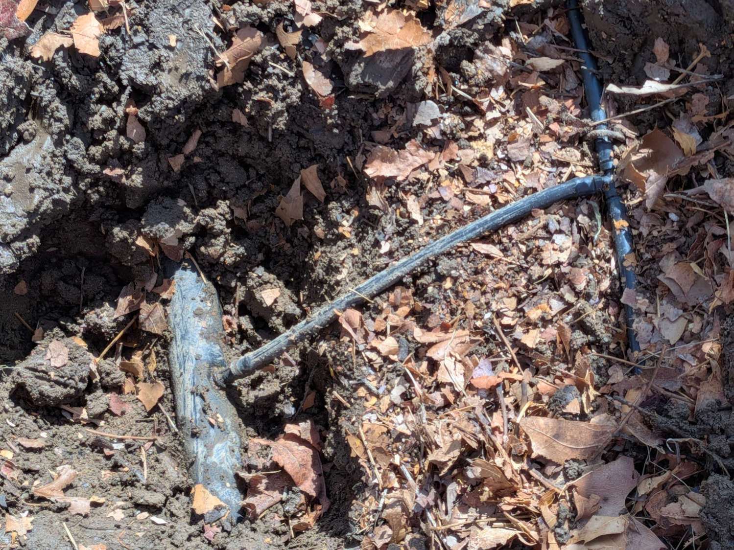
Much of the tubing between the transfer barb in the buried pipe and the cross coupling lies on the surface, where it’s subject to missteps. This being just a few feet inside the garden gate, it’s no surprise enough missteps caused the barb to no longer seal properly.
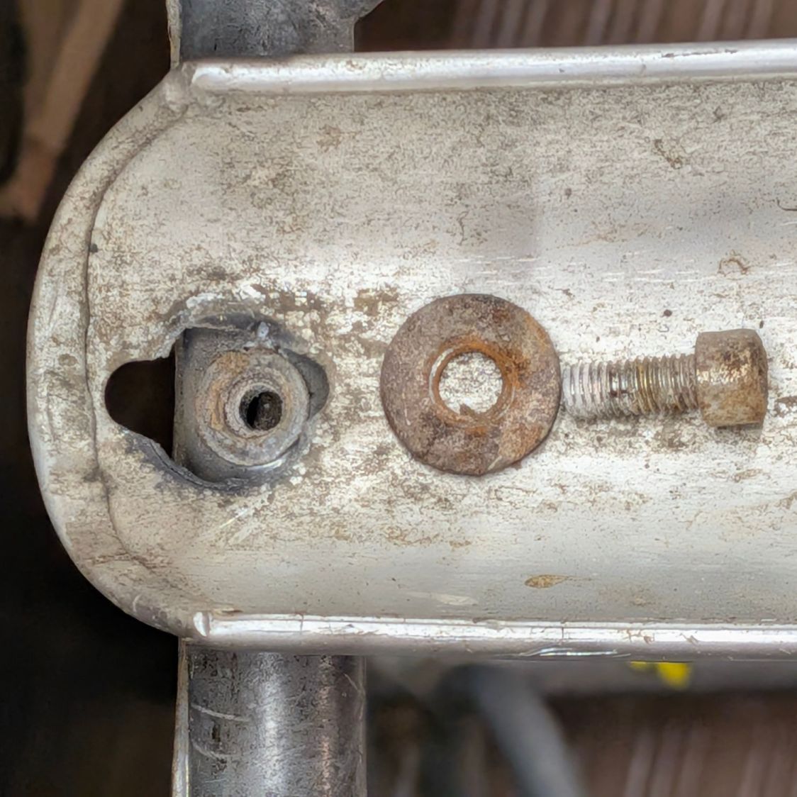
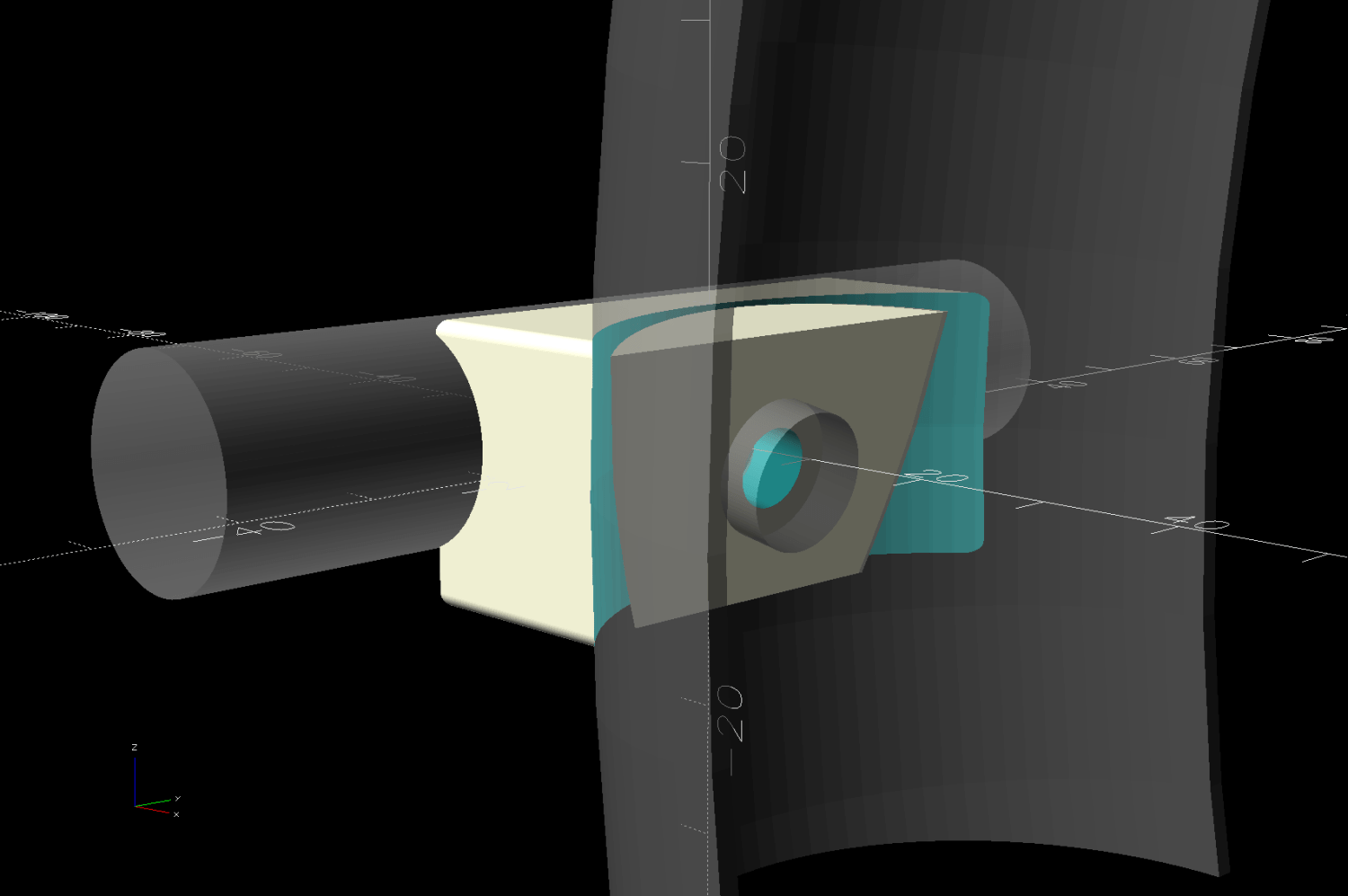
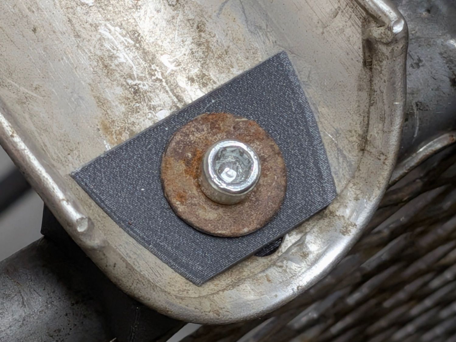
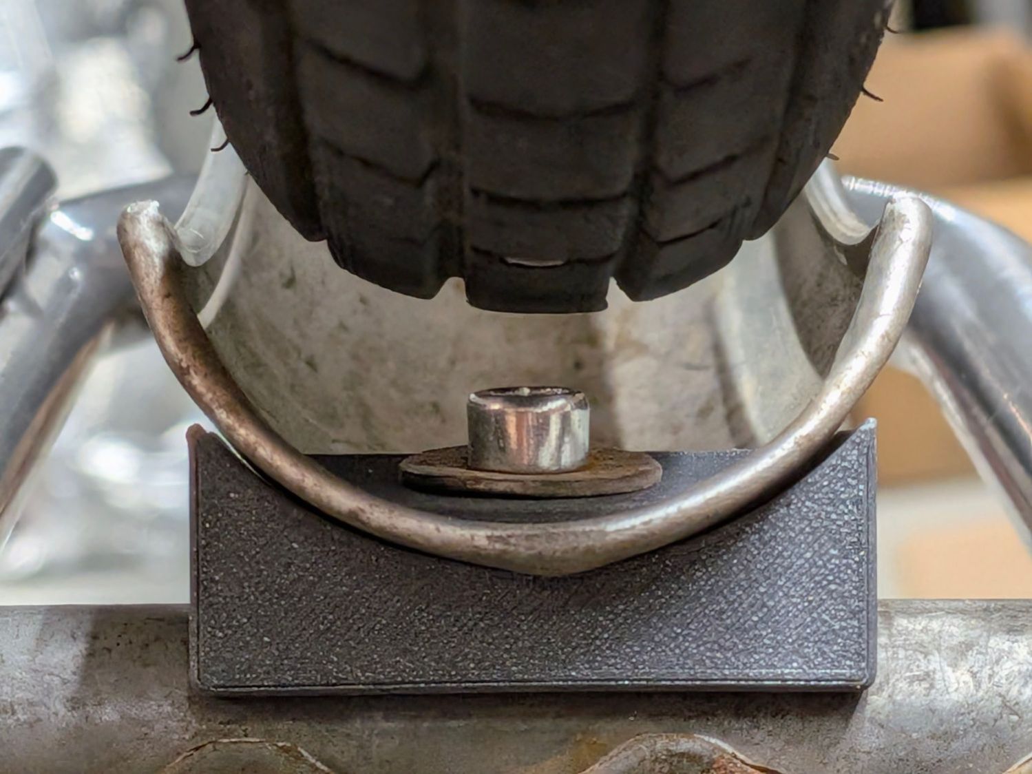
So I pulled the barb out of the pipe and deployed the backup pipe clamp I made after fixing a previous mishap:
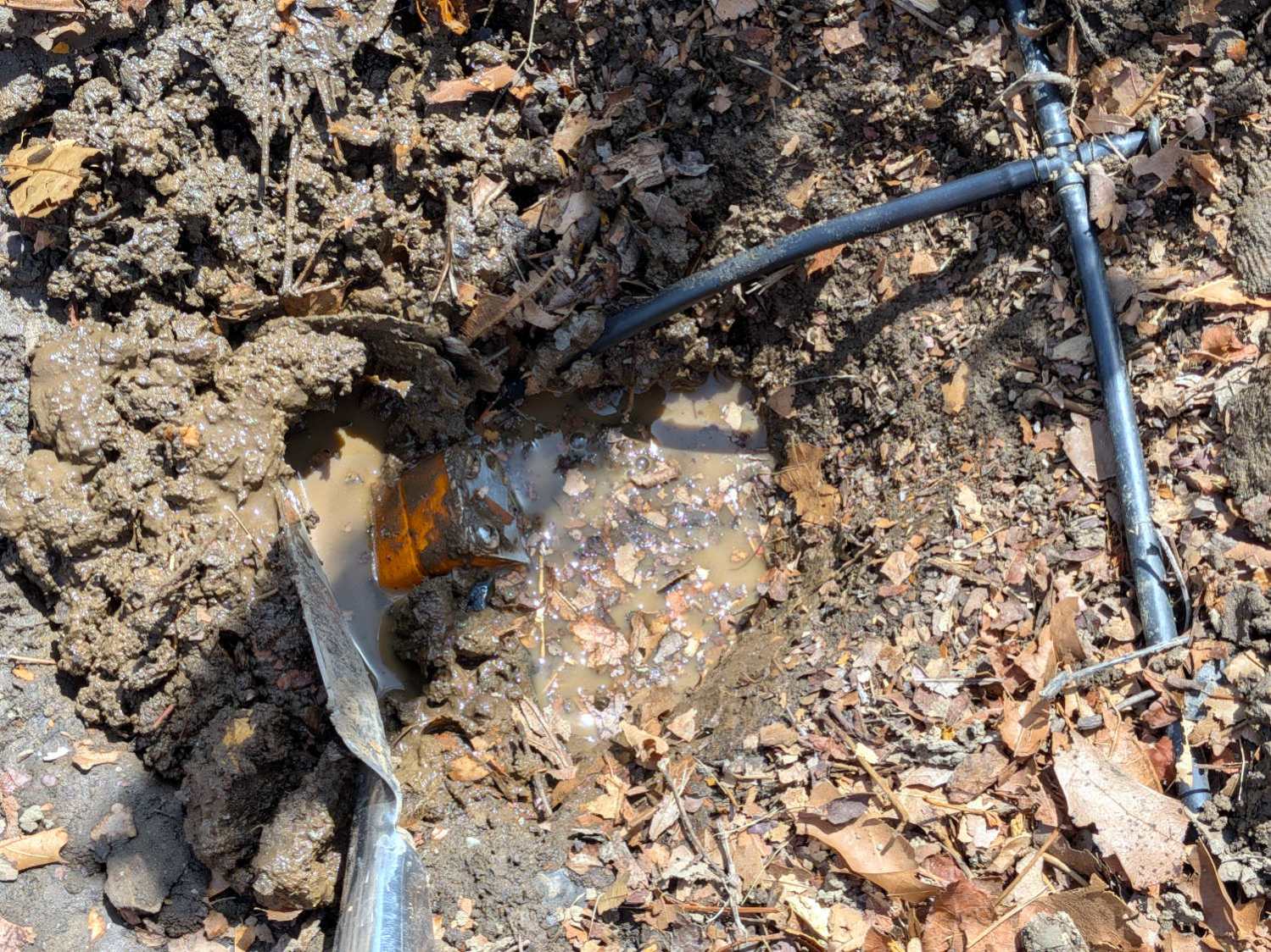
You’re supposed to wrap silicone tape while keeping its surface clean, which is obviously impossible in a hole rapidly filling with water draining from the plumbing but the clamp presses the tape firmly against the pipe and seals the leak.
There is, I regret to say, an 8-32 stainless steel washer lost somewhere deep in the muck.
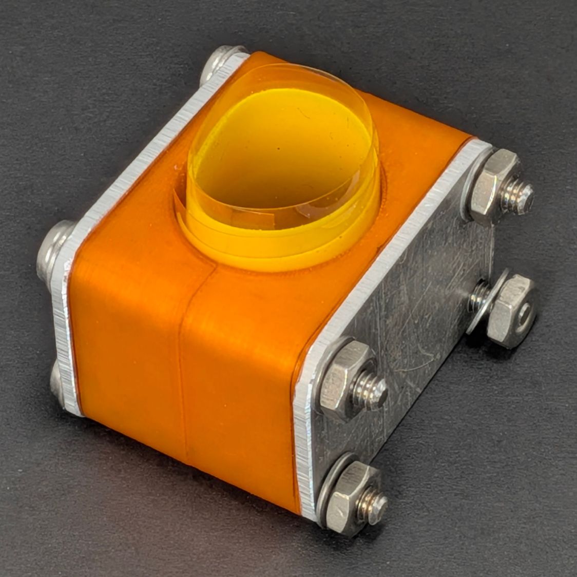
I punched a new barb into the pipe with slightly longer tubing to the cross fitting, in the hope it’ll be more resilient.
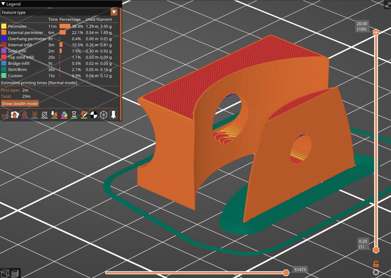
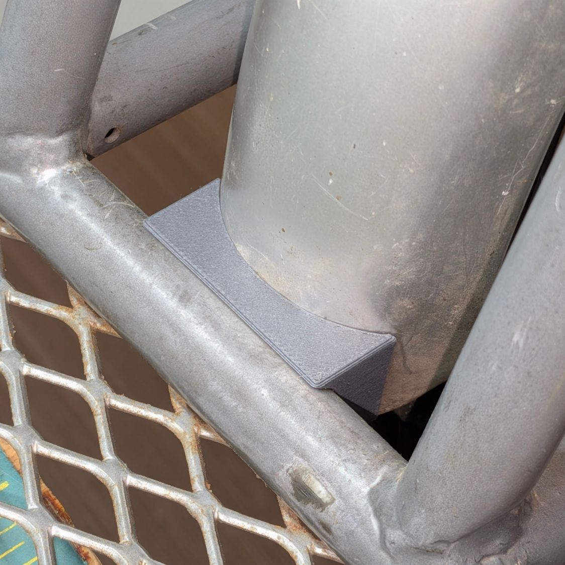
Another clamp with its silicone tape snippet stands ready for duty:
For the record, the Micromark Cutoff Saw has a 3 mm offset between the side of the vise and the left edge of the blade:
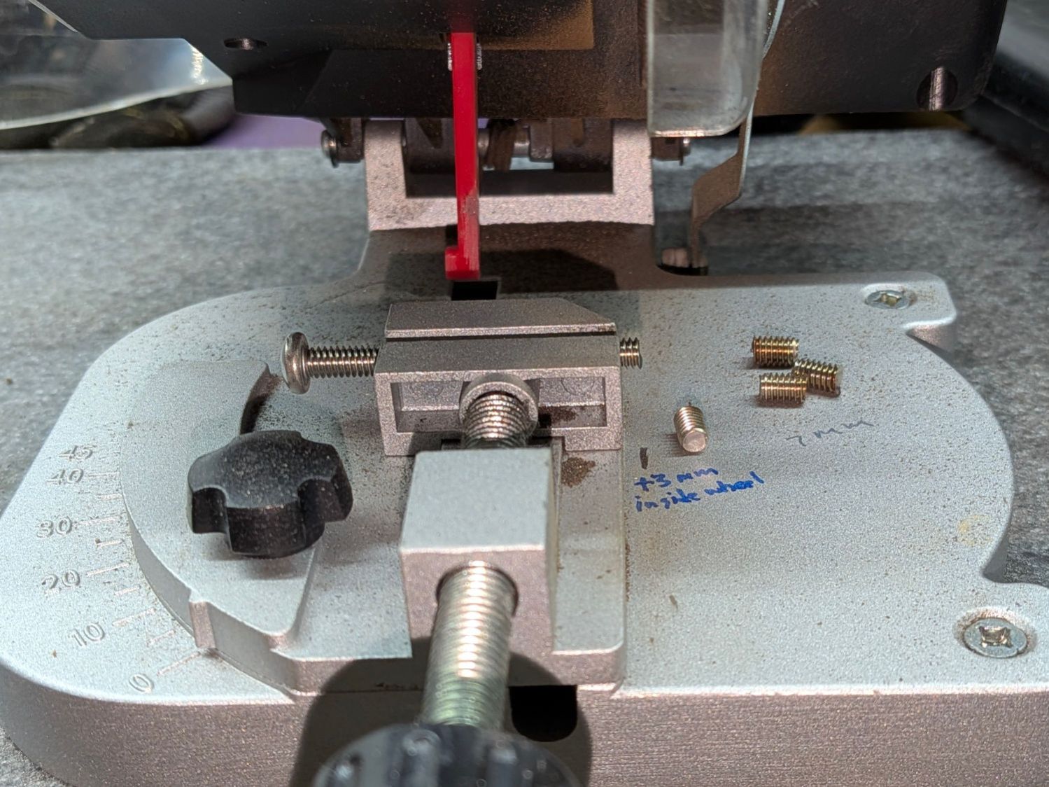
I still lack a Round Tuit for improving that vise.