Ed Nisley's Blog: Shop notes, electronics, firmware, machinery, 3D printing, laser cuttery, and curiosities. Contents: 100% human thinking, 0% AI slop.
So my trustySony DSC-H5 camera emitted a horrible crunching sound from inside its lens assembly, spat out several error codes which boiled down to “throw me out”, stopped retracting its lens, and developed a nasty rattle. If I thought dropping $2k on a fancy mirrorless DSLR would improve my photography, I’d do it, but instead I picked up a $60 used DSC-H5 from eBay and continued the mission.
Of course, the new-to-me H5 suffers from the half-press switch failure common to that entire line of Sony cameras; my DSC-H1 repair notes still come in handy for many folks.
I’d preemptively repaired the shutter button + switch in my now-defunct H5, so I dismantled it, extracted the control assembly + shutter button, bulldozed the debris aside, dismantled the new(er) H5, transplanted the parts, reassembled it, and declared victory.
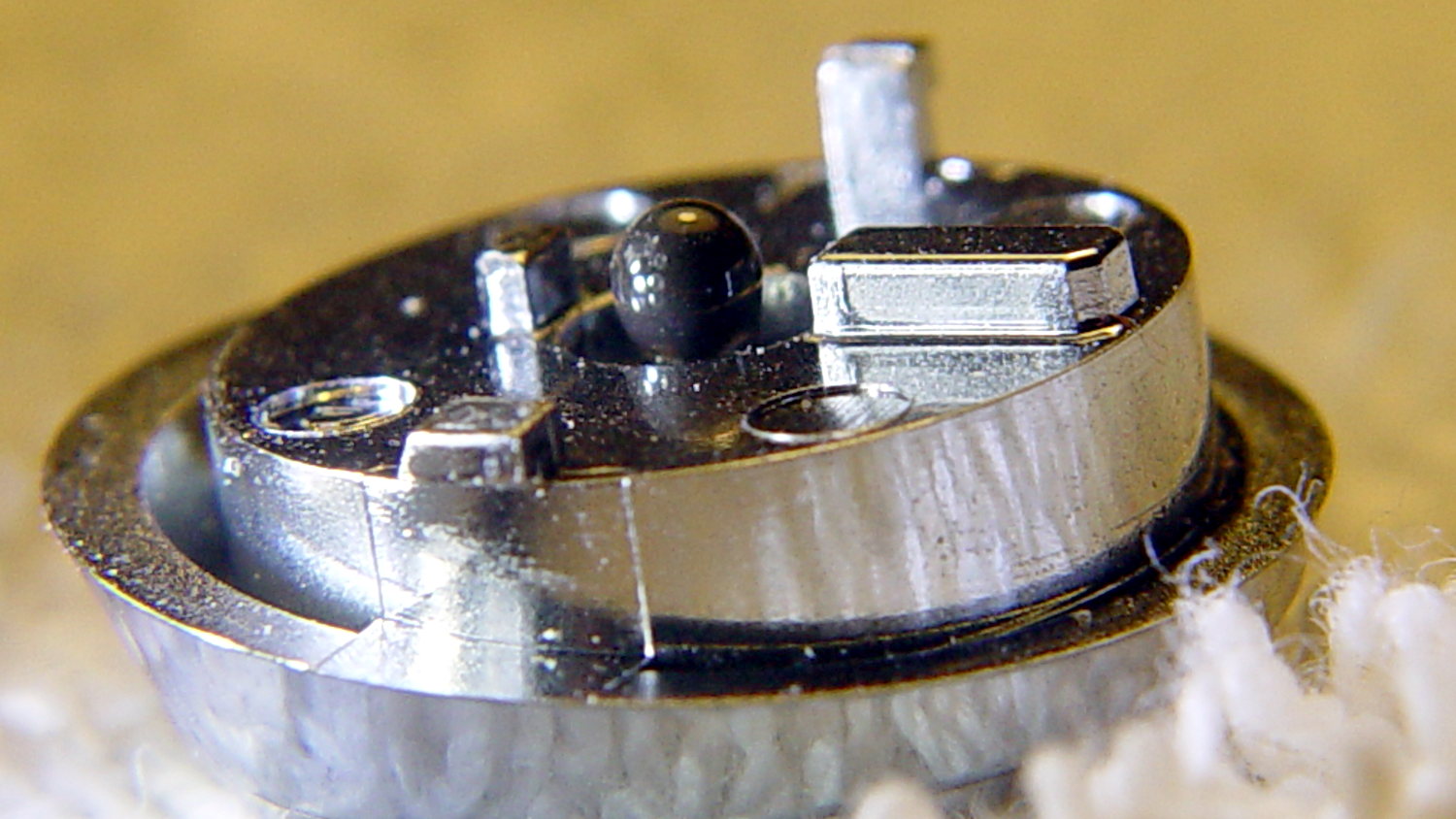
Which left me with a pile of parts that could become an H5, if I could fix the lens assembly, which seemed unlikely. While pondering the futility of human existence, I applied a low-effort repair to the defunct shutter button by scuffing the nicely chromed and absurdly tapered tip of the OEM shutter button’s shaft, then applying a dot of JB Kwik epoxy:
DSC-H5 Shutter Button – epoxy dot
The nice sphere came from hanging downward, with the button sitting atop a short brass tube on the workbench.
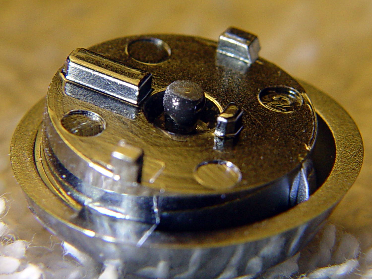
Filing the dot’s end flat produced a blunt plunger much larger than the OEM tip:
DSC-H5 Shutter Button – filed epoxy dot
You can just see the edge of the OEM tip inside the grayish end, which puts the filed flat at the original pin’s length.
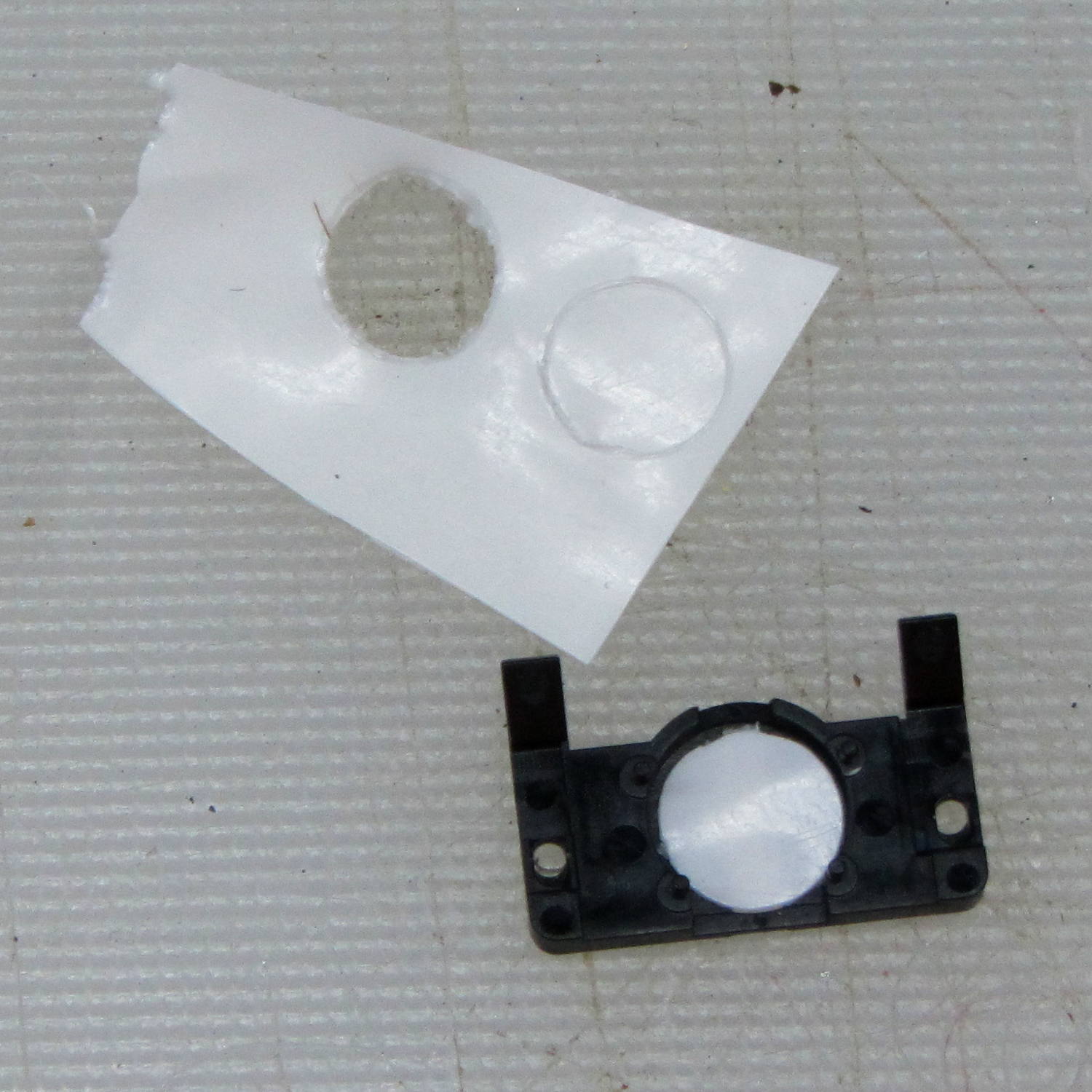
I punched a new plastic disk to replace the indented one:
DSC-H5 – shutter switch cover
Based on past experience, the new plunger tip will work fine, although, unlike the brass screw repair, the OEM plastic pin can still break and launch the spring-loaded shutter button cap into a nearby bush. Given that I may never actually use the repaired button, I’ll take the risk.
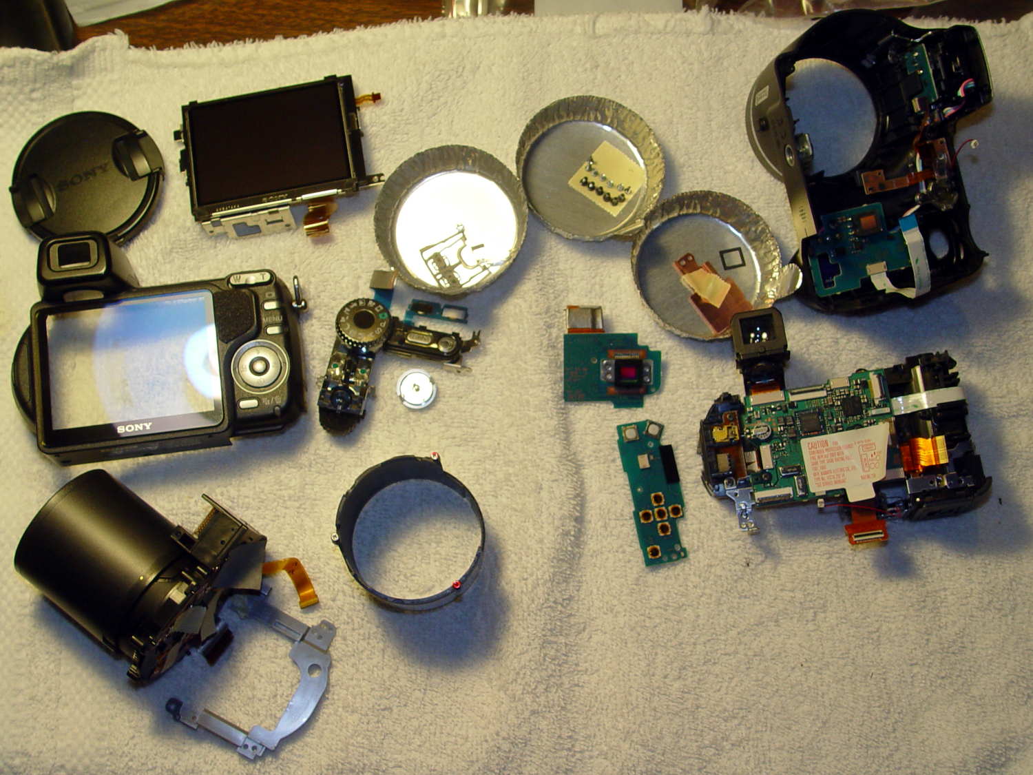
Finding out if the new tip will work may take a while:
DSC-H5 – disassembled
I did a bit more disassembly than strictly necessary to replace the shutter button, but not by much; you’d be crazy to pay me to fix your camera, fer shure.
A pair of torchiere lamps lit the living room for many, many years:
Torchiere Lamp Shade – original
During their tenure, they’ve gone from 100 W incandescent bulbs to “100 W equivalent” CFL curlicues to “100 W equivalent” warm-white LED bulbs. The LEDs aren’t up to the brightness of the original incandescents, but you can get used to anything if you do it long enough.
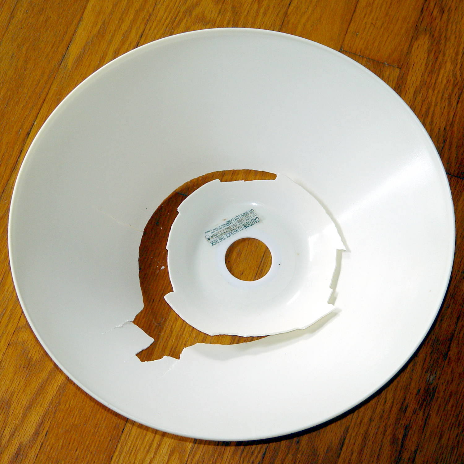
After so many years, the plastic shades / diffusers became brittle:
Torchiere Lamp Shade – original broken
That’s after a bump, not a fall to the floor. So it goes.
Some casual searching didn’t turn up any likely replacements. The shade measures 14 inch = 355 mm across the top, far too large for the M2’s platform, but maybe a smaller shade in natural PETG would work just as well.
ACHTUNG! This is obviously inappropriate for the original incandescent bulbs and would be, IMO, marginal with CFL tubes. Works fine with LEDs. Your mileage may vary.
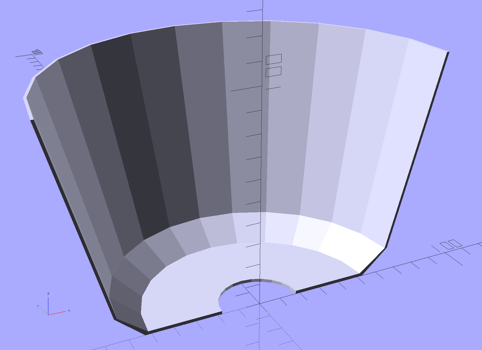
OpenSCAD to the rescue:
Torchiere Lamp Shade – section
That’s a section down the middle. The top is 180 mm across, leaving 20 mm of general caution on the 200 mm width of the platform. The section above the sharply angled base is 90 mm tall to match the actual LED height, thereby putting them out of my line-of-sight even when standing across the room.
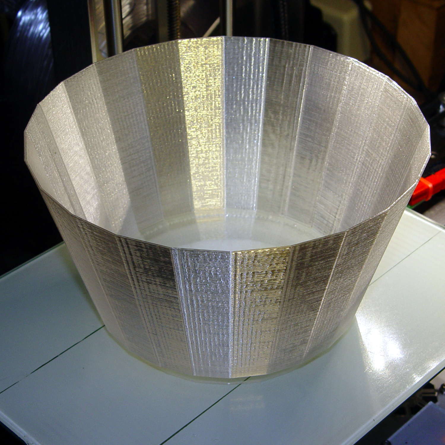
I ran off a short version, corrected the angles and sizes for a better fit, tweaked the thickness to fuse three parallel threads into a semitransparent shell, and …
Torchiere Lamp Shade – M2 platform
Producing what looks like thin flowerpot required just shy of seven hours of print time, as it’s almost entirely perimeter, goin’ down slow for best appearance. The weird gold tone comes from the interaction of camera flash with warm-white CFL can lights over the desk.
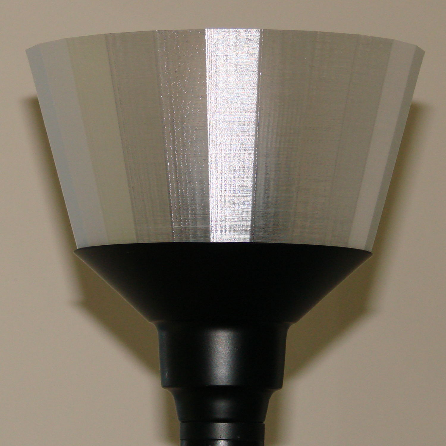
If you hadn’t met the original, you’d say the new shade grew there:
Torchiere Lamp Shade – no epoxy
It’s definitely a Brutalist design, not even attempting to hide its 3D printed origin and glorying in those simple geometric facets.
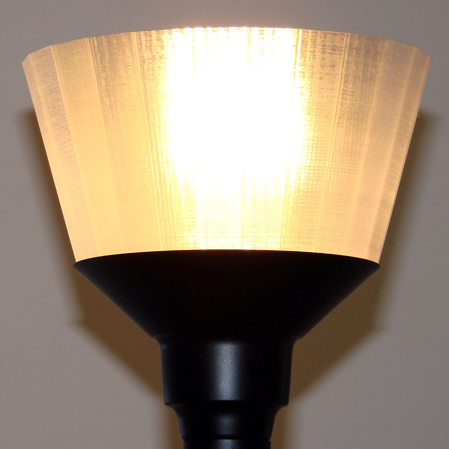
Those three threads of natural PETG makes a reasonably transparent plate, clear enough that the bulb produced an eye-watering glare through the shade:
Torchiere Lamp Shade – no epoxy – lit
So I returned it to the Basement Laboratory, chucked it up in the lathe (where it barely clears the bed), dialed the slowest spindle speed (150 rpm according to the laser tach, faster than I’d prefer), and slathered a thin layer of white-tinted XTC-3D around the inside:
Torchiere Lamp Shade – lathe spinning
For lack of anything smarter, I mixed 2+ drops of Opaque White with 3.1 g of Part A (resin), added 1.3 g of Part B (Hardener), mixed vigorously, drooled the blob along the middle of the rotating shade, spread it across the width using the mixing stick, smoothed it into a thin layer with a scrap of waxed paper, and ignored it for a few hours.
If the lathe perspective looks a bit weird, it’s perfectly natural: I raised the tailstock end enough to make the lower side of the shade just about horizontal. Given the gooey nature of XTC-3D, it wasn’t going anywhere, but I didn’t want a slingout across the lathe bed.
The lit-up result isn’t photographically different from the previous picture, but in person the epoxy layer produces a much nicer diffused light and no glare.
I might be forced to preemptively replace the other shade, just for symmetry, but we’ll let this one age for a while before jumping to conclusions.
This file contains hidden or bidirectional Unicode text that may be interpreted or compiled differently than what appears below. To review, open the file in an editor that reveals hidden Unicode characters.
Learn more about bidirectional Unicode characters
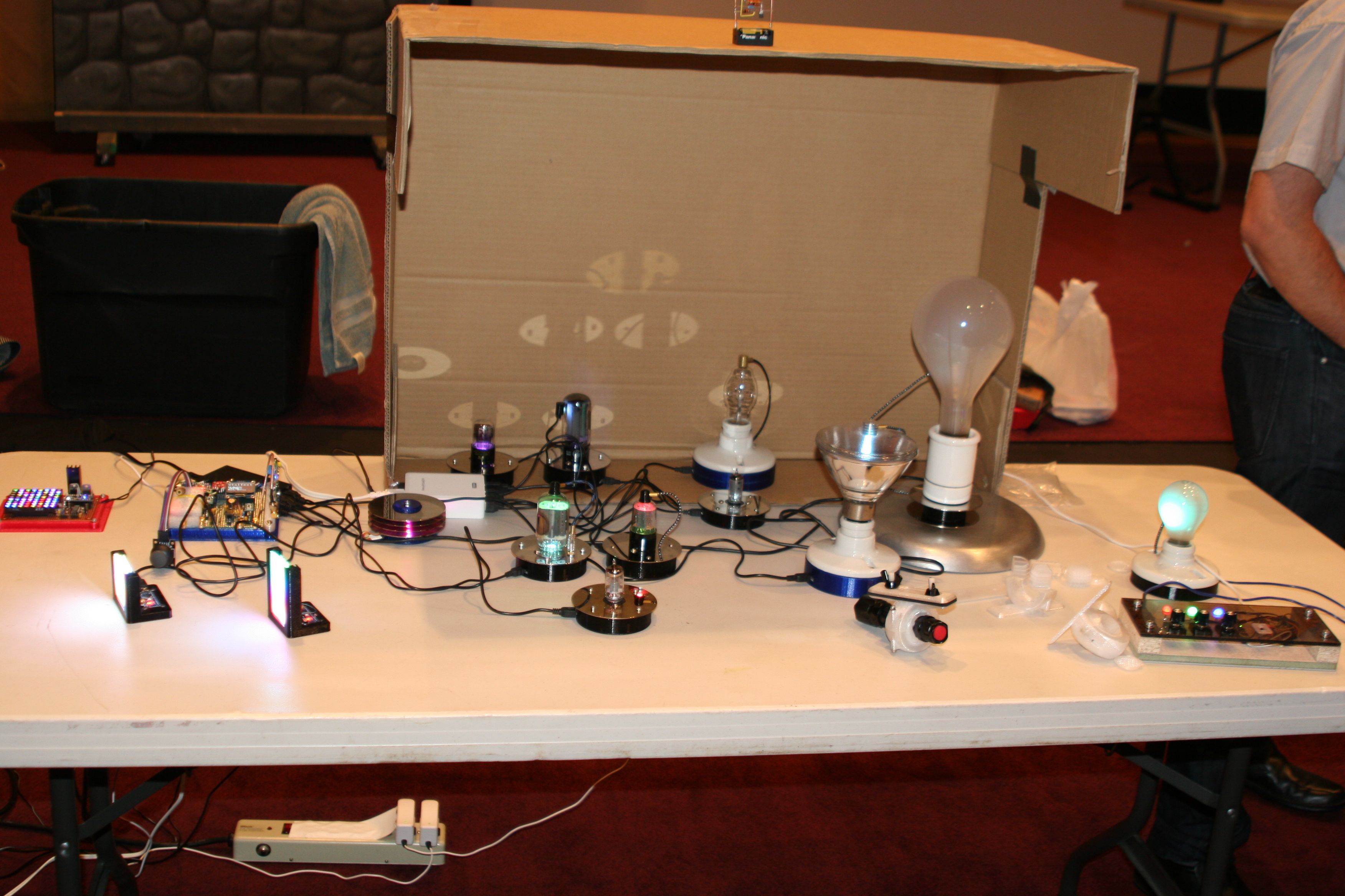
They look much better without a flash, honest. The cut-up cardboard box threw much needed shade; the auditorium has big incandescent can lights directly overhead.
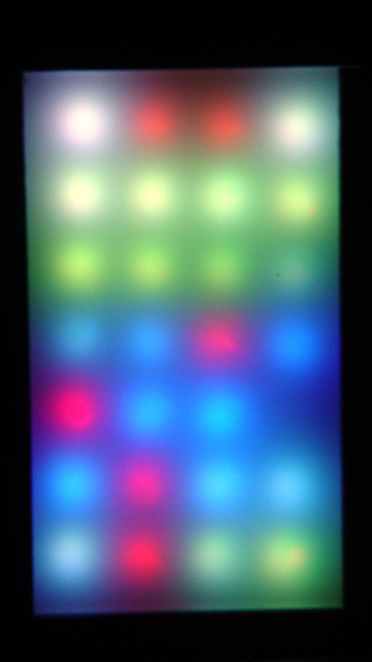
Anyhow, what with one thing and another, the two LED test fixtures spent another few dark and cool days in the Basement Laboratory. When I finally plugged them in, the SK6812 RGBW LED array light up just fine, but three more WS2812 RGB LEDs went toes-up:
WS2812 LED test fixture – more failures
That brought the total to about 8 (one looks like it’s working) out of 28: call it a 28% failure rate. While WS2812 LEDs don’t offer much in the way of reliability, running them continuously seems to minimize the carnage.
So I wired around the new deaders and took that picture.
Flushed with success and anxious to get this over with, I sealed the tester in a plastic bag and tossed it in the freezer for a few hours …
Which promptly killed most of the remaining WS2812 chips, to the extent even a protracted session on the Squidwrench Operating Table couldn’t fix it. When I though I had all the deaders bypassed, an LED early in the string would wig out and flip the panel back to pinball panic mode.
It’s not a 100% failure rate, but close enough: they’re dead to me.
As the remaining WS2812 LEDs on the various vacuum tubes and bulbs go bad, I’m replacing them with SK6812 RGBW LEDs.
For whatever it’s worth, freezing the SK6812 tester had no effect: all 25 LEDs lit up perfectly and run fine. Maybe some of those chips will die in a few days, but, to date, they’ve been utterly reliable.
Having replaced the Dell Optiplex 980 (running from an eBay NOS power supply) with an off-lease Optiplex 9010, I was mildly surprised to find two Displayport outputs from the built-in Intel graphics chipset. Not being a gamer, I don’t care much about graphic performance, but plugging two 2560×1440 monitors into the jacks and having them Just Work was delightful. Indeed, Dell even managed to fix work around the error in the U2711 firmware requiring me to power-cycle the damned thing before booting the PC; now I can just turn the PC on and It Just Works.
Mysteriously, the incantation required to limit the Wacom tablet to the left-hand landscape monitor now uses DP1 instead of HEAD-0:
xsetwacom --verbose set "Wacom Graphire3 6x8 stylus" MapToOutput "DP1"
xsetwacom --verbose set "Wacom Graphire3 6x8 eraser" MapToOutput "DP1"
#xsetwacom --verbose set "Wacom Graphire3 6x8 Pen stylus" MapToOutput "HEAD-0"
#xsetwacom --verbose set "Wacom Graphire3 6x8 Pen eraser" MapToOutput "HEAD-0"
I’ll leave the “HEAD-0 incantations as comments, so as to have a hint the next time …
Every now & again, streaming music from distant servers fails, for no reason I can determine. In that situation, it would be nice to have a local source and, as mplayer works just fine when aimed at an MP3 file, I tried to set up a USB stick on the ASUS router.
That requires getting their version of SAMBA working with the Raspbian Lite installed on the streaming players. After screwing around for far too long, I finally admitted defeat, popped the USB stick into the Raspberry Pi running the APRS iGate in the attic stairwell, and configured it as an NFS server.
To slightly complicate the discussion, there’s also a file server in the basement which turns itself off after its nightly backup. The local music files must be available when it’s off, so the always-up iGate machine gets the job.
On the NFS server:
Install rpcbind and nfs-common, both of which should already be included in stock Raspbian Lite, and nfs-kernel-server, which isn’t. There were problems with earlier Raspbian versions involving the startup order which should be history by now; this post may remind me what’s needed in the event the iGate NFS server wakes up dead after the next power blink.
Set up /etc/exports to share the mount point:
/mnt/music	*(ro,async,insecure,no_subtree_check)
# blank line so you can see the underscores in the previous one
Plug in the USB stick, mount, copy various music directories from the file server’s pile o’ music to the stick’s root directory.
Create a playlist from the directory entries and maybe edit it a bit:
ls -1 /mnt/part/The_Music_Directory > playlist.tmp
sed 's/this/that/' < playlist.tmp > playlist.txt
rm playlist.tmp
Tuck the playlist into the Playlists directory on the basement file server, from whence the streamer’s /etc/rc.local will copy the file to its local directory during the next boot.
On every streamer, create the /mnt/music mountpoint and edit /etc/rc.local to mount the directory:
nfs_music=192.168.1.110
<<< snippage >>>
mount -v -o ro $nfs_music:/mnt/music /mnt/music
# blank line so you can see the underscores in the previous one
In the Python streaming program on the file server, associate the new “station” with a button:
The startup script also fetches the latest copy of the Python program whenever the file server is up, so the new version should Just Work.
I set the numeric keypad button associated with that program as the fallback in case of stream failures, so when the Interwebs go down, we still have music. Life is good …
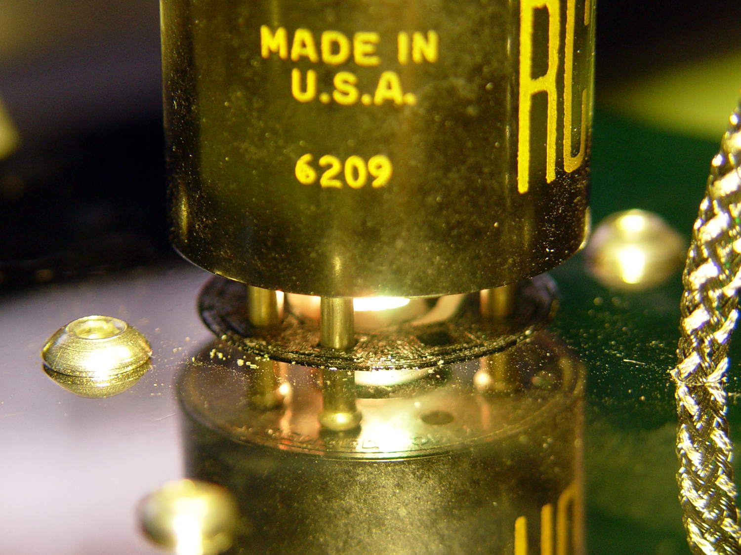
The LEDs adorning the 0D3 rectifier tube became unreliable:
0D3 Octal – 25 mm socket – raised LED
After failing to plug in a different USB power supply, a close look at the USB connector showed the problem:
Knockoff Arduino Nano – broken Mini-B connector
A bit of needle-nosetweezering extracted the culprit from the power supply’s connector:
Knockoff Arduino Nano – broken Mini-B connector – fragment
I tried applying the world’s smallest dot of epoxy to the fracture, probably slobbered epoxy along the pins while reinserting it, and the Nano still doesn’t light up.
Given that knockoff Nano boards cost a touch over two bucks delivered, it’s not clear transplanting a connector from one of the never-sufficiently-to-be-damned counterfeit FTDI USB adapters makes any sense.