The first pass at the crystal tester used a manual jumper to switch the 33 pF series capacitor in / out of the circuit:

With an Arduino close at hand, however, a relay makes somewhat more sense. For long-forgotten reasons, I have a small fortune in Teledyne 732TN-5 relays intended for RF switching:
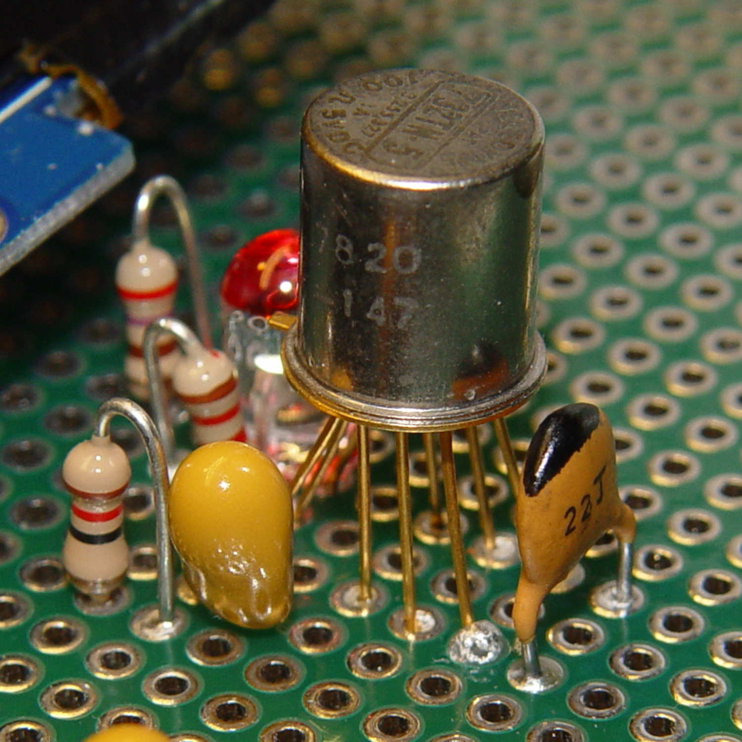
The 7820 date code on the side suggests they’ve been in the heap basically forever, although some fractions of Teledyne still exist and you can apparently buy the same relay today at 50 bucks a pop. It’s definitely overqualified for this job and you can surely get away with an ordinary DIP DPDT (or, heck, even SPST) relay.
It seems I picked a hyper-bright white LED: the red ink tones it down a bit. Black might be more effective. A diffused LED may be in order.
The “TN” suffix indicates a built-in transistor driver with a catch diode on the relay coil, so the relay needs power, ground, and a current drive into the transistor’s base terminal:
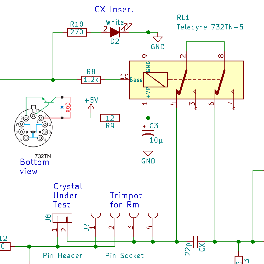
Even with the internal catch diode, I ran the +5 V power through a 12 Ω resistor to a 10 µF cap in hopes of isolating the inevitable switching transients from the DDS and log amp. As a result, the turn-on transient isn’t much of a transient at all:

The 560 mV drop suggests a 47 mA coil current through the 12 Ω resistor, just about spot on for a 100 Ω coil.
The energy stored in the coil makes the turn-off transient much steeper:

Note the 1.5 µs delay from the falling control input to the relay opening. Granted, it’s running at 4.7 V, not the rated 5 V, but that’s still rather peppy. The turn-on delay seems to be about the same, making the datasheet’s “6 ms nominal” operating time look rather conservative.
Dang, that’s a nice gadget!

Comments
3 responses to “Teledyne 732TN-5 Relay: Zowie!”
[…] 22 pF cap now sits across the relay’s NO contacts, so as to simplify measuring the total in-circuit capacitance. The LED turns on when the relay […]
[…] that’s a 3 mm amber LED next to the relay can: much less glaring than the white LED, no matter what it looks like […]
[…] lurid red glow along the bottom is lens flare from the amber LED showing the relay is turned on. The slightly dimmer characters across the middle of the display show how the refresh […]