While tinkering with the SPI code for the AD9850 DDS module, I wrote down the ambient temperature and the frequency tweak required to zero-beat the 10 MHz output with the GPS-locked oscillator. A quick-n-dirty plot summarizing two days of randomly timed observations ensued:
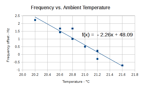
The frequency offset comes from the tweak required to zero-beat the output by adjusting the initial oscillator error: a positive tweak produces a smaller count-per-hertz coefficient and reduces the output frequency. As a result, the thermal coefficient sign is backwards, because increasing temperature raises the oscillator frequency and reduces the necessary tweak. I think so, anyway; you know how these things can go wrong. More automation and reliable data would be a nice touch.
Foam sheets formed a block around the DDS module, isolating it from stray air currents and reducing the clock oscillator’s sensitivity:
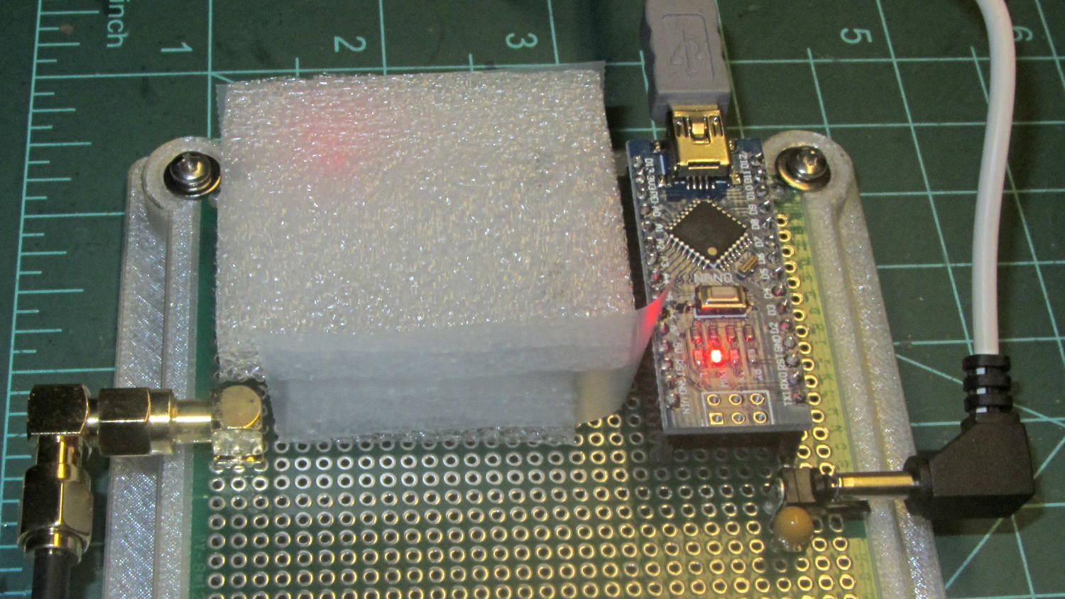
I used the ambient temperature, because the thermocouple inside the foam (not shown in the picture) really wasn’t making good contact with the board, the readings didn’t make consistent sense, and, given a (nearly) constant power dissipation, the (average) oscillator temperature inside the foam should track ambient temperature with a constant offset. I think so, anyway.
The coefficient works out to 0.02 ppm/°C. Of course, the initial frequency offset is something like -400 Hz = 3 ppm, so we’re not dealing with lab-grade instrumentation here.

Comments
9 responses to “AD9850 DDS Module: Temperature Sensitivity”
Just wondering (without any practical experience mind you), do you need shielding between Arduino and DDS?
So far, so good! The DDS produces about 250 mV into a 100 Ω output filter, which seems like enough signal and low-enough resistance to eliminate anything wafting over from the Arduino. I’m punting separate power supplies for the DDS and (eventually) the log amp until an awful problem crops up.
I’ll bet that if you put on your Analog Guru hat, you could whip up a small heater circuit to keep the oscillator can at a pretty constant temp with just a thermistor, a transistor, and maybe a few resistors. Epoxy them all to the can and voila! – a bare bones OCXO. Or maybe the heating element could be one of those nifty cartridge heaters you used in your experiments with the extruder nozzle?
I have no idea if this would work, but all it needs is a dab of epoxy:

Isn’t that just the cutest little Peltier cooler you’ve ever seen?
Without a BIG heat sink it should be called a “Peltier heater”… took me embarrassingly long time to figure that one out when I first started messing with them:)
But it is cute, I’ll give you that :)
Yup, first time around the loop, everybody forgets the “cool” side must get rid of both the IC’s waste heat and its own wattage. If we had Peltier refrigerators in our kitchens, they’d work perfectly well as ovens, too!
[…] The pillars of green wire insulation forestall screwdriver shorts to the bare pin headers, although that’s less of risk with the upper insulating foam sheet in place: […]
[…] A strip of NXP (née Philips plus Freescale, including the part of Motorola that didn’t become ON) LM75A I²C temperature sensors arrived from beyond the horizon. To see if they worked, I soldered thin wires directly to the SO-8 pins, entombed it in Kapton tape to prevent spitzensparken, and jammed it under the foam insulation atop the AD9850 DDS module: […]
[…] peak frequencies differ by 0.2 Hz, which is probably due to a few degrees of temperature difference. Obviously, it’s badly in need of a temperature calibration & […]