Having conjured fixed-point arithmetic into working, the next step is to squirt data to the AD9850 DDS chip. Given that using the Arduino’s hardware-assisted SPI doesn’t require much in the way of software, the wiring looks like this:
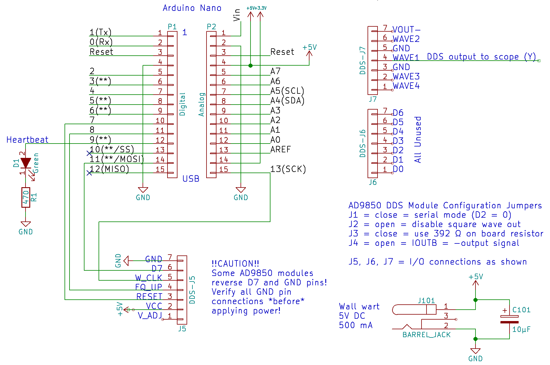
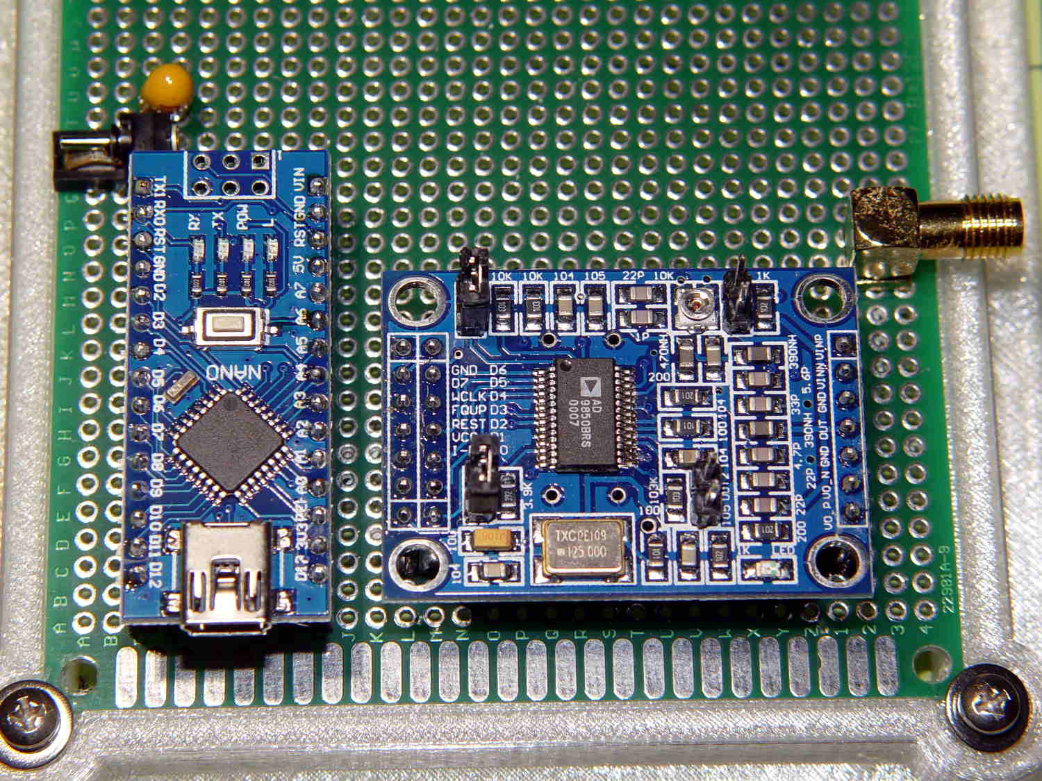
Not much to it, is there? For reference, it looks a lot like you’d expect:
There’s no point in building an asynchronous interface with SPI interrupts and callbacks and all that rot, because squirting one byte at 1 Mb/s (a reasonable speed for hand wiring; the AD9850 can accept bits at 140+ MHz) doesn’t take all that long and it’s easier to have the low-level code stall until the hardware finishes:
#define PIN_HEARTBEAT    9          // added LED

#define PIN_RESET_DDS    7          // Reset DDS module
#define PIN_LATCH_DDS    8          // Latch serial data into DDS

#define PIN_SCK        13          // SPI clock (also Arduino LED!)
#define PIN_MISO      12          // SPI data input
#define PIN_MOSI      11          // SPI data output
#define PIN_SS        10          // SPI slave select - MUST BE OUTPUT = HIGH

void EnableSPI(void) {
  digitalWrite(PIN_SS,HIGH);        // set SPI into Master mode
  SPCR |= 1 << SPE;
}

void DisableSPI(void) {
  SPCR &= ~(1 << SPE);
}

void WaitSPIF(void) {
  while (! (SPSR & (1 << SPIF))) {
    TogglePin(PIN_HEARTBEAT);
    TogglePin(PIN_HEARTBEAT);
    continue;
  }
}

byte SendRecSPI(byte Dbyte) {           // send one byte, get another in exchange
  SPDR = Dbyte;
  WaitSPIF();
  return SPDR;                          // SPIF will be cleared
}
With that in hand, turning on the SPI hardware and waking up the AD9850 looks like this:
void EnableDDS(void) {

  digitalWrite(PIN_LATCH_DDS,LOW);          // ensure proper startup

  digitalWrite(PIN_RESET_DDS,HIGH);         // minimum reset pulse 40 ns, not a problem
  digitalWrite(PIN_RESET_DDS,LOW);
  delayMicroseconds(1);                     // max latency 100 ns, not a problem

  DisableSPI();                             // allow manual control of outputs
  digitalWrite(PIN_SCK,LOW);                // ensure clean SCK pulse
  PulsePin(PIN_SCK);                        //  ... to latch hardwired config bits
  PulsePin(PIN_LATCH_DDS);                  // load hardwired config bits = begin serial mode

  EnableSPI();                              // turn on hardware SPI controls
  SendRecSPI(0x00);                         // shift in serial config bits
  PulsePin(PIN_LATCH_DDS);                  // load serial config bits
}
Given 32 bits of delta phase data and knowing the DDS output phase angle is always zero, you just drop five bytes into a hole in the floor labeled “SPI” and away they go:
void WriteDDS(uint32_t DeltaPhase) {

  SendRecSPI((byte)DeltaPhase);             // low-order byte first
  SendRecSPI((byte)(DeltaPhase >> 8));
  SendRecSPI((byte)(DeltaPhase >> 16));
  SendRecSPI((byte)(DeltaPhase >> 24));

  SendRecSPI(0x00);                         // 5 MSBs = phase = 0, 3 LSBs must be zero

  PulsePin(PIN_LATCH_DDS);                  // write data to DDS
}
In order to have something to watch, the loop() increments the output frequency in steps of 0.1 Hz between 10.0 MHz ± 3 Hz, as set by the obvious global variables:
      PrintFixedPtRounded(Buffer,ScanFreq,1);

      TestCount.fx_64 = MultiplyFixedPt(ScanFreq,CtPerHz);
      printf("%12s -> %9ld\n",Buffer,TestCount.fx_32.high);

      WriteDDS(TestCount.fx_32.high);

      ScanFreq.fx_64 += ScanStep.fx_64;

      if (ScanFreq.fx_64 > (ScanTo.fx_64 + ScanStep.fx_64 / 2)) {
        ScanFreq = ScanFrom;
        Serial.println("Scan restart");
      }
Which produces output like this:
DDS SPI exercise
Ed Nisley - KE4ZNU - May 2017

Inputs: 124999656 = 125000000-344
Osc freq: 124999656.000000000
Hz/Ct: 0.029103750
Ct/Hz: 34.359832926
0.1 Hz Ct: 3.435983287
Test frequency:  10000000.0000
Delta phase: 343598329

Scan limits
 from:   9999997.0
   at:  10000000.0
   to:  10000003.0

Sleeping for a while ...

Startup done!

Begin scanning

  10000000.0 -> 343598329
  10000000.1 -> 343598332
  10000000.2 -> 343598336
  10000000.3 -> 343598339
  10000000.4 -> 343598343
  10000000.5 -> 343598346
  10000000.6 -> 343598349
  10000000.7 -> 343598353
  10000000.8 -> 343598356
  10000000.9 -> 343598360
  10000001.0 -> 343598363
  10000001.1 -> 343598367
  10000001.2 -> 343598370
  10000001.3 -> 343598373
<<< snippage >>>
The real excitement happens while watching the DDS output crawl across the scope screen in relation to the 10 MHz signal from the Z8301 GPS-locked reference:
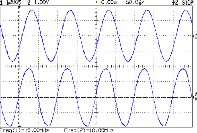
The DDS sine in the upper trace is zero-beat against the GPS reference in the lower trace. There’s no hardware interlock, but they’re dead stationary during whatever DDS output step produces exactly 10.0000000 MHz. The temperature coefficient seems to be around 2.4 Hz/°C, so the merest whiff of air changes the frequency by more than 0.1 Hz.
It’s kinda like watching paint dry or a 3D printer at work, but it’s my paint: I like it a lot!
The Arduino source code as a GitHub Gist:
| // SPI exercise for 60 kHz crystal tester | |
| #include <avr/pgmspace.h> | |
| //——————— | |
| // Pin locations | |
| // SPI uses hardware support: those pins are predetermined | |
| #define PIN_HEARTBEAT 9 // added LED | |
| #define PIN_RESET_DDS 7 // Reset DDS module | |
| #define PIN_LATCH_DDS 8 // Latch serial data into DDS | |
| #define PIN_SCK 13 // SPI clock (also Arduino LED!) | |
| #define PIN_MISO 12 // SPI data input | |
| #define PIN_MOSI 11 // SPI data output | |
| #define PIN_SS 10 // SPI slave select – MUST BE OUTPUT = HIGH | |
| char Buffer[10+1+10+1]; // string buffer for long long conversions | |
| #define GIGA 1000000000LL | |
| #define MEGA 1000000LL | |
| #define KILO 1000LL | |
| struct ll_fx { | |
| uint32_t low; // fractional part | |
| uint32_t high; // integer part | |
| }; | |
| union ll_u { | |
| uint64_t fx_64; | |
| struct ll_fx fx_32; | |
| }; | |
| union ll_u CtPerHz; // will be 2^32 / 125 MHz | |
| union ll_u HzPerCt; // will be 125 MHz / 2^32 | |
| union ll_u One; // 1.0 as fixed point | |
| union ll_u Tenth; // 0.1 as fixed point | |
| union ll_u TenthHzCt; // 0.1 Hz in counts | |
| // All nominal values are integers for simplicity | |
| #define OSC_NOMINAL (125 * MEGA) | |
| #define OSC_OFFSET_NOMINAL (-344LL) | |
| union ll_u OscillatorNominal; // nominal oscillator frequency | |
| union ll_u OscOffset; // … and offset, which will be signed 64-bit value | |
| union ll_u Oscillator; // true oscillator frequency with offset | |
| #define SCAN_WIDTH 6 | |
| #define SCAN_SETTLE 2000 | |
| union ll_u ScanFrom, ScanTo, ScanFreq, ScanStep; // frequency scan settings | |
| union ll_u TestFreq,TestCount; // useful variables | |
| #define HEARTBEAT_MS 3000 | |
| unsigned long MillisNow,MillisThen; | |
| //———– | |
| // Useful functions | |
| // Pin twiddling | |
| void TogglePin(char bitpin) { | |
| digitalWrite(bitpin,!digitalRead(bitpin)); // toggle the bit based on previous output | |
| } | |
| void PulsePin(char bitpin) { | |
| TogglePin(bitpin); | |
| TogglePin(bitpin); | |
| } | |
| // SPI I/O | |
| void EnableSPI(void) { | |
| digitalWrite(PIN_SS,HIGH); // set SPI into Master mode | |
| SPCR |= 1 << SPE; | |
| } | |
| void DisableSPI(void) { | |
| SPCR &= ~(1 << SPE); | |
| } | |
| void WaitSPIF(void) { | |
| while (! (SPSR & (1 << SPIF))) { | |
| TogglePin(PIN_HEARTBEAT); | |
| TogglePin(PIN_HEARTBEAT); | |
| continue; | |
| } | |
| } | |
| byte SendRecSPI(byte Dbyte) { // send one byte, get another in exchange | |
| SPDR = Dbyte; | |
| WaitSPIF(); | |
| return SPDR; // SPIF will be cleared | |
| } | |
| // DDS module | |
| void EnableDDS(void) { | |
| digitalWrite(PIN_LATCH_DDS,LOW); // ensure proper startup | |
| digitalWrite(PIN_RESET_DDS,HIGH); // minimum reset pulse 40 ns, not a problem | |
| digitalWrite(PIN_RESET_DDS,LOW); | |
| delayMicroseconds(1); // max latency 100 ns, not a problem | |
| DisableSPI(); // allow manual control of outputs | |
| digitalWrite(PIN_SCK,LOW); // ensure clean SCK pulse | |
| PulsePin(PIN_SCK); // … to latch hardwired config bits | |
| PulsePin(PIN_LATCH_DDS); // load hardwired config bits = begin serial mode | |
| EnableSPI(); // turn on hardware SPI controls | |
| SendRecSPI(0x00); // shift in serial config bits | |
| PulsePin(PIN_LATCH_DDS); // load serial config bits | |
| } | |
| // Write delta phase count to DDS | |
| // This comes from the integer part of a 64-bit scaled value | |
| void WriteDDS(uint32_t DeltaPhase) { | |
| SendRecSPI((byte)DeltaPhase); // low-order byte first | |
| SendRecSPI((byte)(DeltaPhase >> 8)); | |
| SendRecSPI((byte)(DeltaPhase >> 16)); | |
| SendRecSPI((byte)(DeltaPhase >> 24)); | |
| SendRecSPI(0x00); // 5 MSBs = phase = 0, 3 LSBs must be zero | |
| PulsePin(PIN_LATCH_DDS); // write data to DDS | |
| } | |
| //———– | |
| // Round scaled fixed point to specific number of decimal places: 0 through 8 | |
| // You should display the value with only Decimals characters beyond the point | |
| // Must calculate rounding value as separate variable to avoid mystery error | |
| uint64_t RoundFixedPt(union ll_u TheNumber,unsigned Decimals) { | |
| union ll_u Rnd; | |
| // printf(" round before: %08lx %08lx\n",TheNumber.fx_32.high,TheNumber.fx_32.low); | |
| Rnd.fx_64 = (One.fx_64 / 2) / (pow(10LL,Decimals)); | |
| // printf(" incr: %08lx %08lx\n",Rnd.fx_32.high,Rnd.fx_32.low); | |
| TheNumber.fx_64 = TheNumber.fx_64 + Rnd.fx_64; | |
| // printf(" after: %08lx %08lx\n",TheNumber.fx_32.high,TheNumber.fx_32.low); | |
| return TheNumber.fx_64; | |
| } | |
| //———– | |
| // Multiply two unsigned scaled fixed point numbers without overflowing a 64 bit value | |
| // The product of the two integer parts mut be < 2^32 | |
| uint64_t MultiplyFixedPt(union ll_u Mcand, union ll_u Mplier) { | |
| union ll_u Result; | |
| Result.fx_64 = ((uint64_t)Mcand.fx_32.high * (uint64_t)Mplier.fx_32.high) << 32; // integer parts (clear fract) | |
| Result.fx_64 += ((uint64_t)Mcand.fx_32.low * (uint64_t)Mplier.fx_32.low) >> 32; // fraction parts (always < 1) | |
| Result.fx_64 += (uint64_t)Mcand.fx_32.high * (uint64_t)Mplier.fx_32.low; // cross products | |
| Result.fx_64 += (uint64_t)Mcand.fx_32.low * (uint64_t)Mplier.fx_32.high; | |
| return Result.fx_64; | |
| } | |
| //———– | |
| // Long long print-to-buffer helpers | |
| // Assumes little-Endian layout | |
| void PrintHexLL(char *pBuffer,union ll_u FixedPt) { | |
| sprintf(pBuffer,"%08lx %08lx",FixedPt.fx_32.high,FixedPt.fx_32.low); | |
| } | |
| // converts all 9 decimal digits of fraction, which should suffice | |
| void PrintFractionLL(char *pBuffer,union ll_u FixedPt) { | |
| union ll_u Fraction; | |
| Fraction.fx_64 = FixedPt.fx_32.low; // copy 32 fraction bits, high order = 0 | |
| Fraction.fx_64 *= GIGA; // times 10^9 for conversion | |
| Fraction.fx_64 >>= 32; // align integer part in low long | |
| sprintf(pBuffer,"%09lu",Fraction.fx_32.low); // convert low long to decimal | |
| } | |
| void PrintIntegerLL(char *pBuffer,union ll_u FixedPt) { | |
| sprintf(pBuffer,"%lu",FixedPt.fx_32.high); | |
| } | |
| void PrintFixedPt(char *pBuffer,union ll_u FixedPt) { | |
| PrintIntegerLL(pBuffer,FixedPt); // do the integer part | |
| pBuffer += strlen(pBuffer); // aim pointer beyond integer | |
| *pBuffer++ = '.'; // drop in the decimal point, tick pointer | |
| PrintFractionLL(pBuffer,FixedPt); | |
| } | |
| void PrintFixedPtRounded(char *pBuffer,union ll_u FixedPt,unsigned Decimals) { | |
| char *pDecPt; | |
| //char *pBase; | |
| // pBase = pBuffer; | |
| FixedPt.fx_64 = RoundFixedPt(FixedPt,Decimals); | |
| PrintIntegerLL(pBuffer,FixedPt); // do the integer part | |
| // printf(" Buffer int: [%s]\n",pBase); | |
| pBuffer += strlen(pBuffer); // aim pointer beyond integer | |
| pDecPt = pBuffer; // save the point location | |
| *pBuffer++ = '.'; // drop in the decimal point, tick pointer | |
| PrintFractionLL(pBuffer,FixedPt); | |
| // printf(" Buffer all: [%s]\n",pBase); | |
| if (Decimals == 0) | |
| *pDecPt = 0; // 0 places means discard the decimal point | |
| else | |
| *(pDecPt + Decimals + 1) = 0; // truncate string to leave . and Decimals chars | |
| // printf(" Buffer end: [%s]\n",pBase); | |
| } | |
| //———– | |
| // Calculate useful "constants" from oscillator info | |
| // Args are integer constants in Hz | |
| void CalcOscillator(uint32_t Base,uint32_t Offset) { | |
| union ll_u Temp; | |
| Oscillator.fx_32.high = Base + Offset; // get true osc frequency from integers | |
| Oscillator.fx_32.low = 0; | |
| HzPerCt.fx_32.low = Oscillator.fx_32.high; // divide oscillator by 2^32 with simple shifting | |
| HzPerCt.fx_32.high = 0; | |
| CtPerHz.fx_64 = -1; // Compute (2^32 – 1) / oscillator | |
| CtPerHz.fx_64 /= (uint64_t)Oscillator.fx_32.high; // remove 2^32 scale factor from divisor | |
| TenthHzCt.fx_64 = MultiplyFixedPt(Tenth,CtPerHz); // 0.1 Hz as delta-phase count | |
| if (true) { | |
| printf("Inputs: %ld = %ld%+ld\n",Base+Offset,Base,Offset); | |
| PrintFixedPt(Buffer,Oscillator); | |
| printf("Osc freq: %s\n",Buffer); | |
| PrintFixedPt(Buffer,HzPerCt); | |
| printf("Hz/Ct: %s\n",Buffer); | |
| PrintFixedPt(Buffer,CtPerHz); | |
| printf("Ct/Hz: %s\n",Buffer); | |
| PrintFixedPt(Buffer,TenthHzCt); | |
| printf("0.1 Hz Ct: %s",Buffer); | |
| } | |
| } | |
| //– Helper routine for printf() | |
| int s_putc(char c, FILE *t) { | |
| Serial.write(c); | |
| } | |
| //———– | |
| void setup () | |
| { | |
| pinMode(PIN_HEARTBEAT,OUTPUT); | |
| digitalWrite(PIN_HEARTBEAT,HIGH); // show we got here | |
| Serial.begin (115200); | |
| fdevopen(&s_putc,0); // set up serial output for printf() | |
| Serial.println (F("DDS SPI exercise")); | |
| Serial.println (F("Ed Nisley – KE4ZNU – May 2017\n")); | |
| // DDS module controls | |
| pinMode(PIN_LATCH_DDS,OUTPUT); | |
| digitalWrite(PIN_LATCH_DDS,LOW); | |
| pinMode(PIN_RESET_DDS,OUTPUT); | |
| digitalWrite(PIN_RESET_DDS,HIGH); | |
| // configure SPI hardware | |
| SPCR = B01110001; // Auto SPI: no int, enable, LSB first, master, + edge, leading, f/16 | |
| SPSR = B00000000; // not double data rate | |
| pinMode(PIN_SS,OUTPUT); | |
| digitalWrite(PIN_SCK,HIGH); | |
| pinMode(PIN_SCK,OUTPUT); | |
| digitalWrite(PIN_SCK,LOW); | |
| pinMode(PIN_MOSI,OUTPUT); | |
| digitalWrite(PIN_MOSI,LOW); | |
| pinMode(PIN_MISO,INPUT_PULLUP); | |
| TogglePin(PIN_HEARTBEAT); // show we got here | |
| // Calculate useful constants | |
| One.fx_64 = 1LL << 32; // Set up 1.0, a very useful constant | |
| Tenth.fx_64 = One.fx_64 / 10; // Likewise, 0.1 | |
| // Calculate oscillator "constants" | |
| CalcOscillator(OSC_NOMINAL,OSC_OFFSET_NOMINAL); | |
| TogglePin(PIN_HEARTBEAT); // show we got here | |
| // Set up 10 MHz calibration output | |
| TestFreq.fx_64 = One.fx_64 * (10 * MEGA); | |
| PrintFixedPtRounded(Buffer,TestFreq,4); | |
| printf("\nTest frequency: %s\n",Buffer); | |
| TestCount.fx_64 = MultiplyFixedPt(TestFreq,CtPerHz); // convert delta phase counts | |
| TestCount.fx_64 = RoundFixedPt(TestCount,0); // … to nearest integer | |
| PrintFixedPt(Buffer,TestCount); | |
| printf("Delta phase: %lu\n",TestCount.fx_32.high); | |
| // Set up scan limits | |
| ScanFreq = TestFreq; | |
| ScanStep.fx_64 = One.fx_64 / 10; // 0.1 Hz = 3 or 4 tuning register steps | |
| ScanFrom.fx_64 = ScanFreq.fx_64 – SCAN_WIDTH * (One.fx_64 >> 1); // centered on test freq | |
| ScanTo.fx_64 = ScanFreq.fx_64 + SCAN_WIDTH * (One.fx_64 >> 1); | |
| Serial.println("\nScan limits"); | |
| PrintFixedPtRounded(Buffer,ScanFrom,1); | |
| printf(" from: %11s\n",Buffer); | |
| PrintFixedPtRounded(Buffer,ScanFreq,1); | |
| printf(" at: %11s\n",Buffer); | |
| PrintFixedPtRounded(Buffer,ScanTo,1); | |
| printf(" to: %11s\n",Buffer); | |
| // Wake up and load the DDS | |
| EnableDDS(); | |
| WriteDDS(TestCount.fx_32.high); | |
| Serial.println("\nSleeping for a while …"); | |
| delay(15 * 1000); | |
| Serial.println("\nStartup done!"); | |
| Serial.println("\nBegin scanning\n"); | |
| MillisThen = millis(); | |
| } | |
| //———– | |
| void loop () { | |
| MillisNow = millis(); | |
| if ((MillisNow – MillisThen) >= SCAN_SETTLE) { | |
| TogglePin(PIN_HEARTBEAT); | |
| MillisThen = MillisNow; | |
| if (true) { | |
| PrintFixedPtRounded(Buffer,ScanFreq,1); | |
| TestCount.fx_64 = MultiplyFixedPt(ScanFreq,CtPerHz); | |
| printf("%12s -> %9ld\n",Buffer,TestCount.fx_32.high); | |
| WriteDDS(TestCount.fx_32.high); | |
| ScanFreq.fx_64 += ScanStep.fx_64; | |
| if (ScanFreq.fx_64 > (ScanTo.fx_64 + ScanStep.fx_64 / 2)) { | |
| ScanFreq = ScanFrom; | |
| Serial.println("Scan restart"); | |
| } | |
| } | |
| } | |
| } | |
| DDS SPI exercise | |
| Ed Nisley – KE4ZNU – May 2017 | |
| Inputs: 124999656 = 125000000-344 | |
| Osc freq: 124999656.000000000 | |
| Hz/Ct: 0.029103750 | |
| Ct/Hz: 34.359832926 | |
| 0.1 Hz Ct: 3.435983287 | |
| Test frequency: 10000000.0000 | |
| Delta phase: 343598329 | |
| Scan limits | |
| from: 9999997.0 | |
| at: 10000000.0 | |
| to: 10000003.0 | |
| Sleeping for a while … | |
| Startup done! | |
| Begin scanning | |
| 10000000.0 -> 343598329 | |
| 10000000.1 -> 343598332 | |
| 10000000.2 -> 343598336 | |
| 10000000.3 -> 343598339 | |
| 10000000.4 -> 343598343 | |
| 10000000.5 -> 343598346 | |
| 10000000.6 -> 343598349 | |
| 10000000.7 -> 343598353 | |
| 10000000.8 -> 343598356 | |
| 10000000.9 -> 343598360 | |
| 10000001.0 -> 343598363 | |
| 10000001.1 -> 343598367 | |
| 10000001.2 -> 343598370 | |
| 10000001.3 -> 343598373 |

Comments
3 responses to “AD9850 DDS Module: Hardware Assisted SPI and Fixed-point Frequency Stepping”
[…] on the proto board with the Arduino and AD9850 DDS ticking away on the left; the bright red MCP4725 DAC will eventually drive the scope’s X […]
[…] AD8950 DDS output feeds a 70 MHz (-ish) elliptical reconstruction filter chopping off image frequencies descending […]
[…] sufficient motivation, I can now calibrate the DDS output against the GPS-locked 10 MHz standard to get a (most likely) linear equation for the oscillator […]