Ed Nisley's Blog: Shop notes, electronics, firmware, machinery, 3D printing, laser cuttery, and curiosities. Contents: 100% human thinking, 0% AI slop.
The switch I installed on Mary’s bike a year ago was intended for indoor use only and, without any trace of weather sealing, recently became intermittent. No surprise, as it’s happened before, but, by regarding my vast assortment of little switches as consumables, we get a low-profile / tactile / E-Z push PTT button without forming a deep emotional attachment.
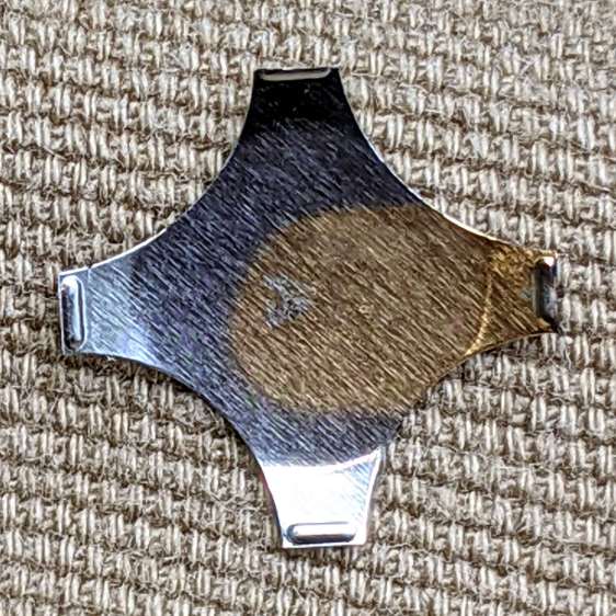
Anyhow, you can see the unsealed square perimeter of the switch actuator:
Tour Easy – PTT button
The light-gray button sits on a post molded into the actuator. Pry the actuator out and the switch dome shows crud worn off the cross-shaped plunger:
Tour Easy – PTT button – dome plate
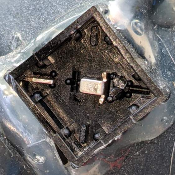
The underside of the dome has a weird golden discoloration that surely wasn’t original:
Tour Easy – PTT button – dome plate discoloration
I have no idea how a liquid (?) could have gotten in there and done that without leaving other traces along the way. The contact bump on the discolored leg had some crud built up around it which responded well to a small screwdriver.
Contrary to what the symmetrical four-legged dome might suggest, only one leg rests on a contact in a corner:
Tour Easy – PTT button – contacts
So, yes, a bit of dirt / corrosion / mystery juice in a single spot could render the whole thing intermittent.
I removed the obvious crud from the obvious spots, wiped everything down with some Caig DeoxIT, reassembled in reverse order, and it seems to be all good again. Of course, these things only fail on the road, so it’ll take a few rides to verify the fix.
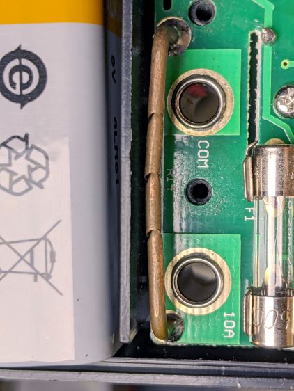
Replacing the battery in an old Craftsman (!) multimeter brought its 10 A current-sense resistor into the light:
Multimeter current resistor – nipped copper wire
Unlike the contemporary AN8008/9 meters, it looks like an ordinary copper wire trimmed to the proper resistance by nipping it with a cutter.
It measures something under 10 mΩ, so I’m sure they adjusted the resistance by applying a known current and watching the meter reading while crunching the wire until the proper value appears.
I may have actually used the 10 A range, but I’d be hard pressed to say when or why, so the resistor is at least as good as it needs to be!
These appeared while I was extricating the 3-axis positioner from an old project:
Migrated felt-tip pen labels
I’m reasonably sure those labels started with blue ink from my all-time favorite Ultra-Fine-Point Sharpie markers on address labels covered with ordinary matte tape. Fourteen years on, the X, Y, and Drive legends are pretty much indistinguishable.
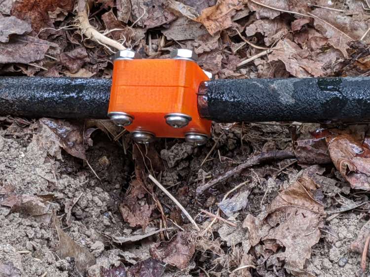
An aging round soaker hose sprang a leak large enough to gouge a crater under a tomato plant, so I conjured a short clamp from the longer round hose splints:
Soaker Hose Clamp – round – installed
The shiny stuff is the plastic backing on strips of silicone tape intended to prevent the high-pressure water from squirting through the porous 3D printed plastic. The fat drop hanging from the hose shows some leakage around the tape; an occasional drop is perfectly OK.
The leak faces the round side of the bottom half of the clamp, which probably doesn’t make any difference.
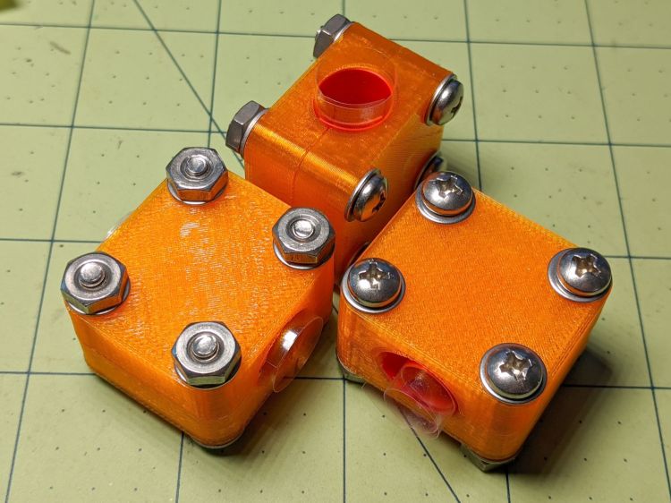
I hope the washers occupy enough of the minimal surface to render aluminum backing plates superfluous:
Soaker Hose Clamp – round – kitted
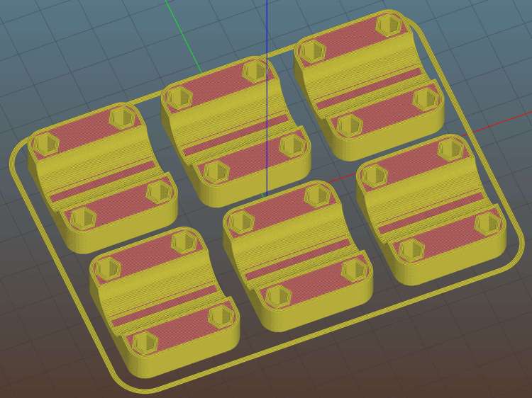
Creating the 3D model required nothing more than shortening the original splint to 30 mm with two screws along each side. While I was at it, I had Slic3r make three clamps to put two in the Garden Dedicated Hydraulic Repair Kit for later use:
Round Soaker Hose Splice – 30mm – Slic3r
Change two lines in the OpenSCAD code and it’s done.
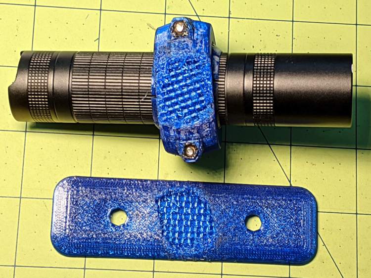
While clearing some overhanging brush along the rail trail, I probably wedged a branch between the LC40 flashlight and the fairing:
Fairing Flashlight Mount – brush clearing
Aaaand twisted it enough to fracture the mount:
Fairing Flashlight Mount – another fracture
A closer look shows the infill just ripped apart:
Fairing Flashlight Mount – another failure – detail
I can’t be sure that’s what happened, because the mount actually failed several miles later, after I hit one of the potholes along Raymond Avenue. Fortunately, I saw it swinging away from the fairing, hanging by its last few threads, and managed to grab it before it vanished.
Fairing Flashlight Mount – Catch a Falling Mount
I set Slic3r for 30% infill on the replacement, but the running light been riding my fairing for three years and seems strong enough under normal use.
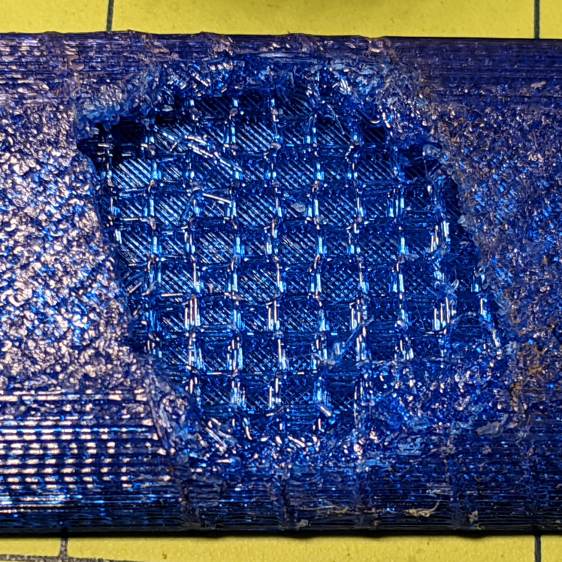
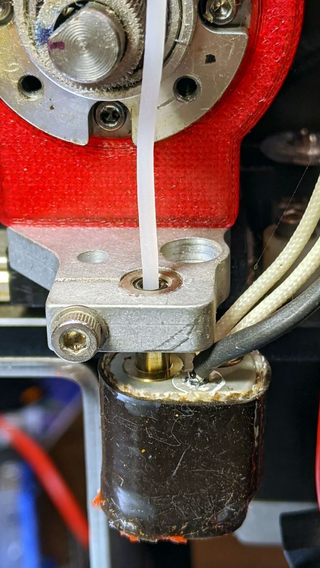
The test pieces for the Mesh Screen Frame came out a bit short:
Extruder Clog – failed print
Which turned out to be the M2’s first extruder clog in a long, long time. The printer shut down normally, with no error messages, and the objects look fine as far as they go, making the diagnosis fairly simple.
The filament still didn’t feed with the drive gear turning
It’s worth noting I use only PETG plastic from a single supplier, so Slic3r uses set-and-forget temperature and speed values, and I manually change colors only on those rare occasions when color matters. Most clogs occur after switching from a higher- to a lower-temperature plastic (PETG to PLA), where a chunk of soft-but-not-molten plastic jams in the nozzle; not the situation here.
Undo the various screws holding the block to the drive gear housing and pull it off. The drive block looked fine, with a clear round hole along the entire filament path, so that’s not the problem.
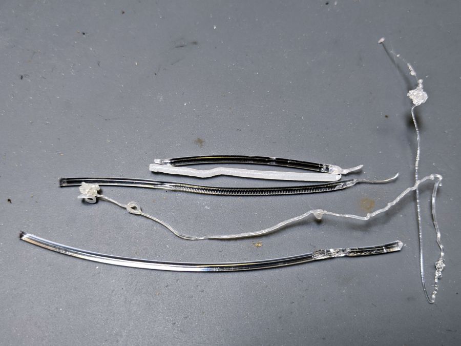
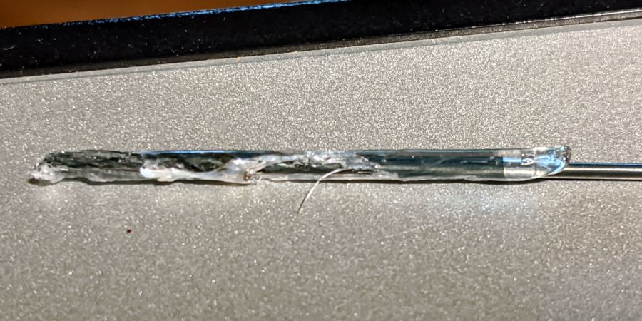
The filament snippet sticking up out of the hot end also looked fine, apart from the expected drive gear gouge, with nice serrations below that point into the hot end. It’s the third filament from the top in this group photo:
Extruder Clog – filament snippets
Although it’s called a “cold pull“, you can’t yank a solid hunk of plastic out of the hot end. Warming the PETG to around 200 °C and pulling the snippet out produced the long tapered end shown above.
I rammed another snippet into the hot end to bond with whatever was inside:
Extruder Clog – PETG pull
Which produced the top snippet above, with no particular trouble found.
Repeating the process with some nylon (?) cleaning filament:
Extruder Clog – cleaner pull
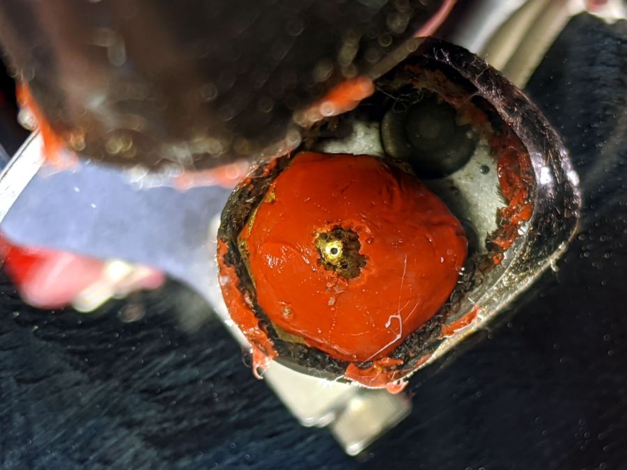
In need of more traction, I sank a #60 twist drill into the molten plastic:
Extruder Clog – drill bit insertion
Let things cool a bit, haul it out (it’s halfway in the picture above), and we’re making progress:
Extruder Clog – drill bit extraction
I warmed the PETG-encrusted bit over a butane flame, wiped it on a shop rag to get most of the plastic off, then drilled a few holes in a hardwood block.
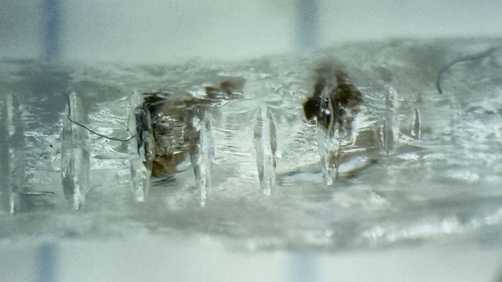
Note that a #60 drill (40 mil = 1 mm) is much much much larger than the nozzle hole:
Extruder Clog – nozzle view
The vertiginous view looks downward into a small hand-held mirror.
Although some folks swear by 0.3 mm carbide drills for nozzle cleaning, I doubt I could avoid wrecking that nice round 0.35 mm hole. The new red silicone coat has chipped from around the nozzle over the last few sessions, so it’s no longer wiping the top layer.
During all this flailing, something that might have been a glass fiber emerged from the nozzle while shoving one of those PETG snippets into the hot end. Of course, when I pried it out of the goo with tweezers, it snapped away into the clutter, never to be seen again. Despite being covered in PETG, it was a rigid sliver, rather than the gooey extruded thread. Perhaps the whisker extending from the PETG surrounding the drill bit was a similar fiber, but I didn’t notice it at the time.
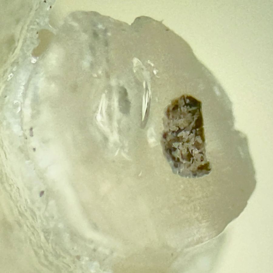
One of the PETG cold warm pulls contained two brownish lumps:
Extruder Clog – PETG inclusions
This chunk doesn’t appear in the group portrait. It’s obviously been melted, measures a bit under 1.75 mm diameter, and the drive gear tooth marks show it passed through the filament drive block under motor control, most likely retraction.
Passing the Xacto Knife of Inquiry through the leftmost lump split it neatly in two. The left section:
Extruder Clog – PETG inclusion – section L
And the right section:
Extruder Clog – PETG inclusion – section R
In person, the sections look like granular / burned residue surrounded by clear PETG. I’d expect anything burned to come from inside the hot end, but I don’t know how those lumps would get surrounded by nice, clear PETG inside a reasonably cylindrical section with drive gear notches.
Anyhow, the clog has now Gone Away™ and the M2 extrudes just fine. I’ll declare victory and move on …
My favorite half-teaspoon measure hit the floor with a surprising sproing:
Half-teaspoon soldering – broken
The weld lasted far longer than anyone should own a spoon, I suppose, but it wasn’t much to begin with:
Half-teaspoon soldering – sprung handle
Having had much the same thing happen to a measuring cup from the same set, I cleaned the back of the spoon and the front of the handle with a stainless steel wire brush in the Dremel and gingerly re-bent the handle to remove any inclination it might have to break free again:
Half-teaspoon soldering – cleaned and rebent
Some 60% silver solder (the formula evidently changed in the last few decades), nasty flux, and propane torch work produced a decent fillet:
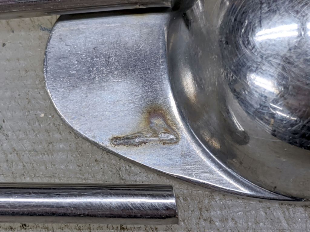
Half-teaspoon soldering – cooling
It looks a bit worse on the far side, but I’ll never tell.
Rinse off the flux, wire-brush the joint, wash again, and it’s all good.
I thought about excavating the resistance soldering gadget, but the torch was closer to hand and a bigger fillet seemed in order.