Ed Nisley's Blog: Shop notes, electronics, firmware, machinery, 3D printing, laser cuttery, and curiosities. Contents: 100% human thinking, 0% AI slop.
Just for completeness, here’s what the various soaker hose clamps look like in the garden, as solid models only let you visualize the ideal situation:
Soaker Hose Connector Clamp – Show view
This one prevents a puddle in the path to the right:
Soaker hose repairs in situ – clamp
Bending the hoses around the end of a bed puts them on edge, with this clamp suppressing a shin-soaking spray to the left:
Soaker hose repairs in situ – end-on clamp
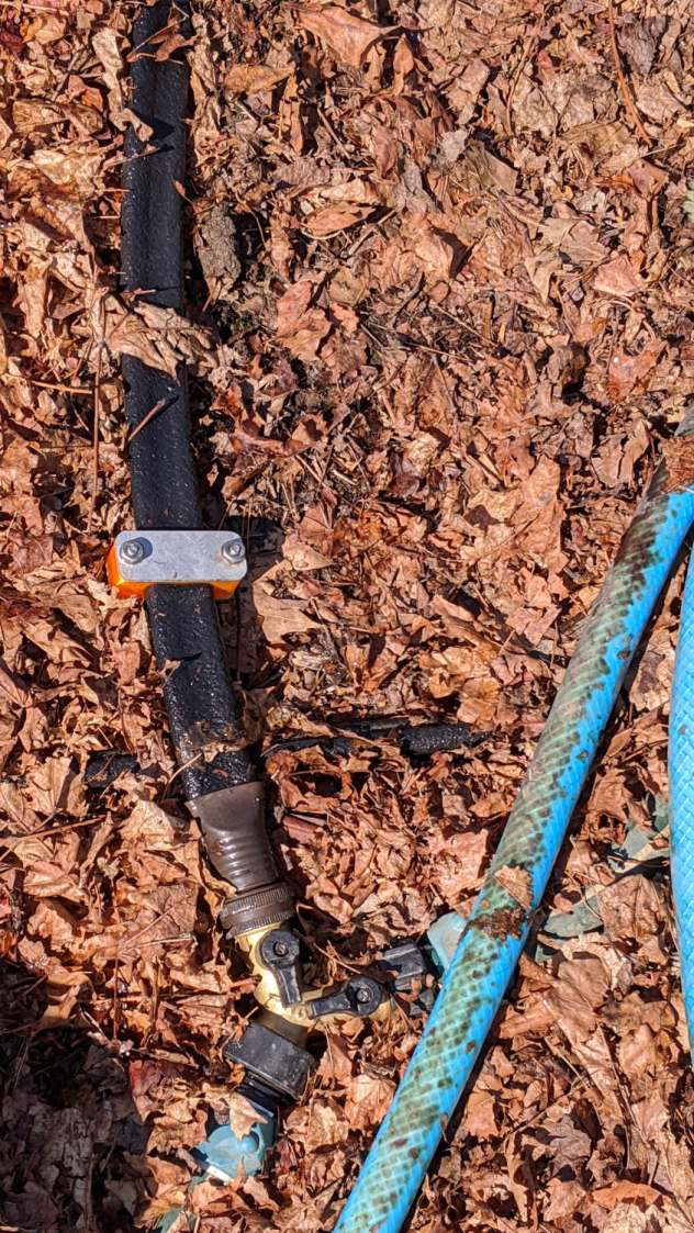
The clamp at the connector closes a leak around the crimped brass fitting, with the other two preventing gouges from direct sprays into the path along the bottom of the picture:
Soaker hose repairs in situ – clamps and connector fix
All in all, a definite UI improvement!
As far as I can tell, we have the only soaker hose repairs & spritz stoppers in existence. Hooray for 3D printing!
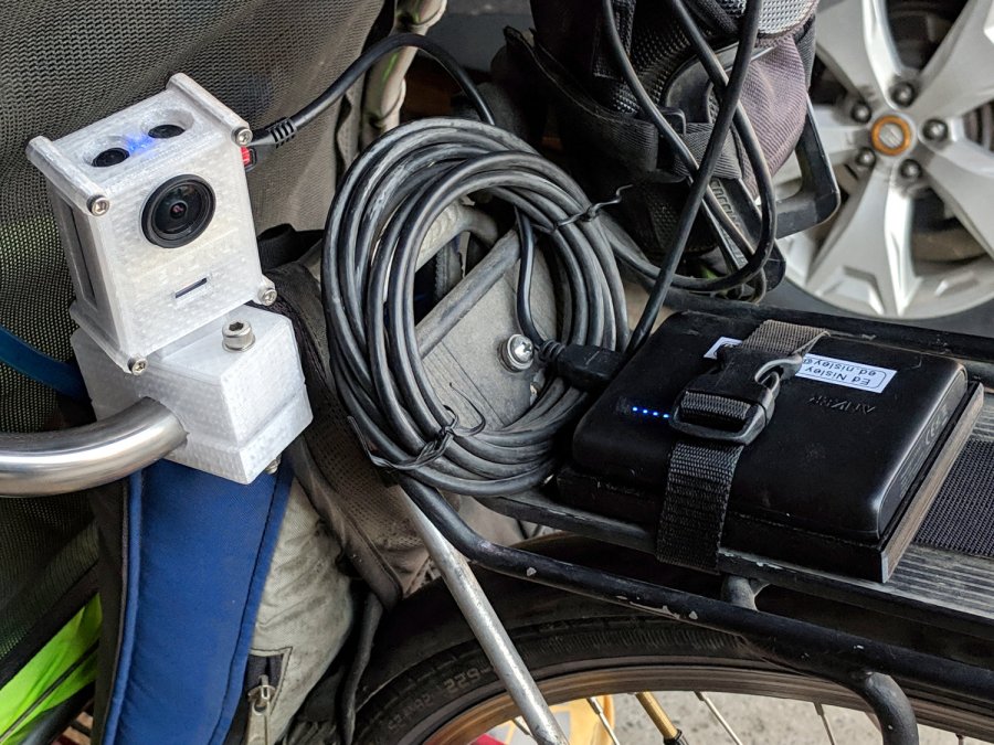
The Anker 13 A·h USB power pack on the rack provides juice for a week’s worth of rides, letting the M20’s internal battery keep its clock & settings alive between rides. I recently forgot to turn on the USB pack and discovered the camera shut down just after I cleared the end of the driveway.
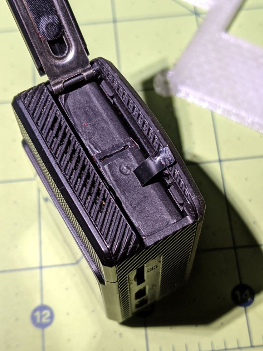
As you should expect, the battery had swollen so much its pull tab … pulled off … when I tried to extract it:
SJCAM M20 – stuck battery
So, we begin.
Pry off the trim ring around the lens by jamming a small screwdriver in any of the three slots:
SJCAM M20 – lens ring removed
Then pry off the entire front panel:
SJCAM M20 – camera front panel
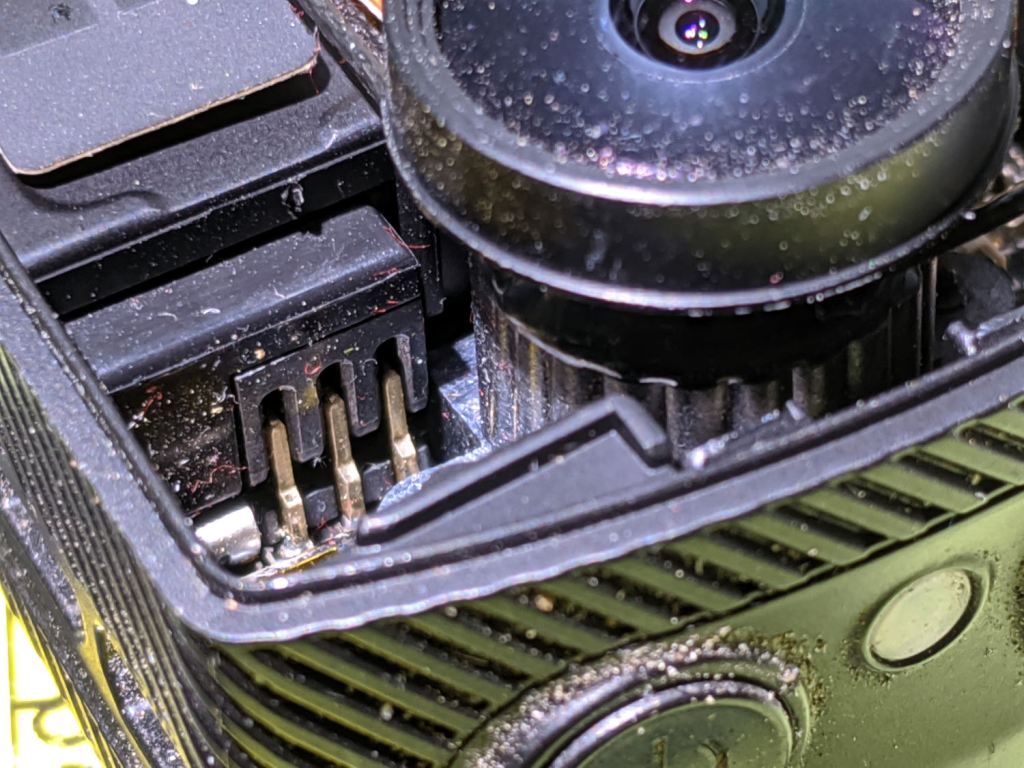
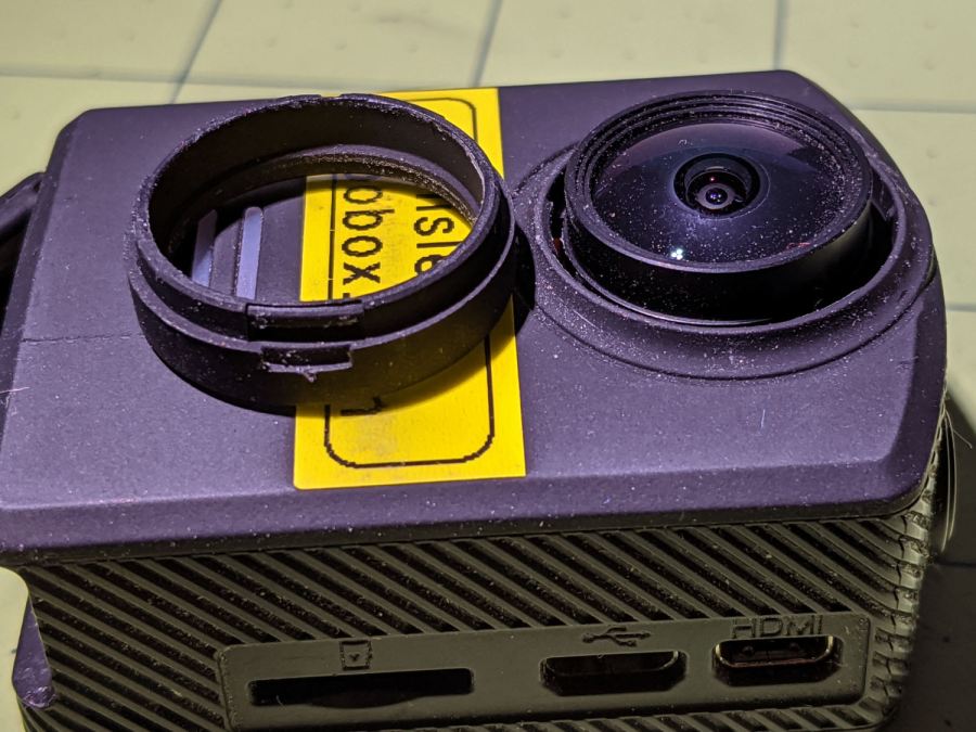
Thereby exposing the battery’s rectangular protrusion and three contacts next to the optical block:
SJCAM M20 – camera interior – battery terminals
Avoid shorting the brass terminals with, say, a small screwdriver, while shoving the battery out of the camera until you can grab it with your fingers and haul it out the rest of the way:
SJCAM M20 – swollen battery case – left
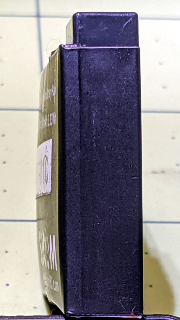
Yeah, that puppy looks all swoll up:
SJCAM M20 – swollen battery case – right
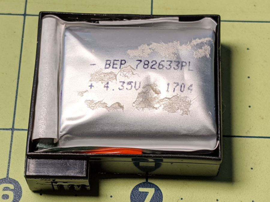
Remove the all-enclosing label to reveal the bag inside:
SJCAM M20 – swollen battery bag
Pull the bag out to reveal the protection PCB:
SJCAM M20 – battery case interior
Snip the wires and salvage the case against future need.
I bought the camera with three batteries, all three of which are now similarly swollen. I also got two official SJAM batteries with an official SJAM charger; both of those batteries seem to be in fine shape. I expect the codes on the five bags would reveal two different lots, but I’m not going to sacrifice a nominally good battery to find out.
All three swollen battery bags show the same BEP 782633PL lot code and 1704 date code. I bought everything in January 2018, so those batteries had been sitting on the shelf for the better part of a year. Maybe that’s why they offered a “deal” for two spare batteries along with the camera?
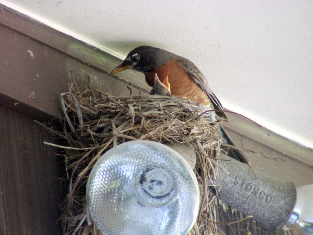
Installing one of the unswollen batteries, reconfiguring the camera’s settings & clock, and giving it a charge from the Anker USB pack put it back in operation.
Nothing prizewinning, but better than no picture at all:
Garage Robin – recovered image
Note that you start by copying a reasonable chunk of the partition from the Memory Stick / (micro)SD Card first, to prevent a bad situation from getting worse.
Now I can remember the easy way the next time around this block …
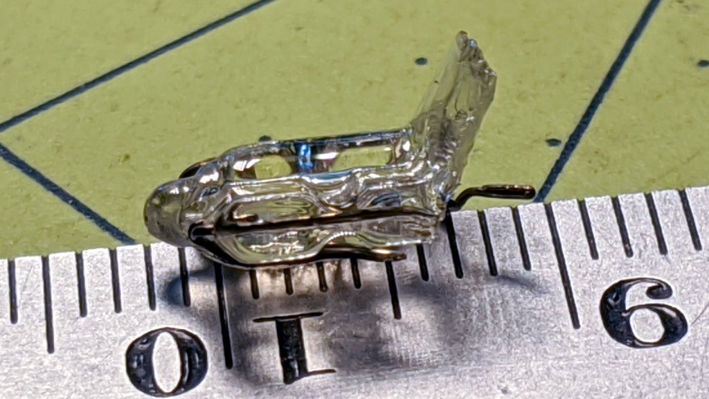
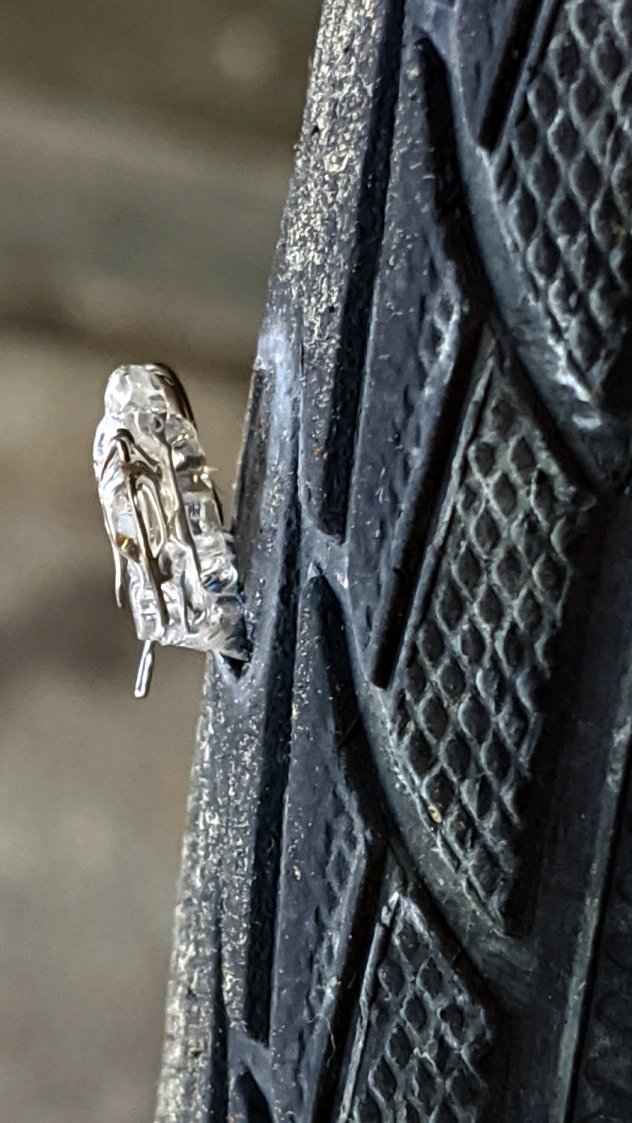
A clicking sound from the rear of the bike suggested something was amiss as I rolled up the driveway after a recent ride. Spinning the rear tire produced this alarming sight:
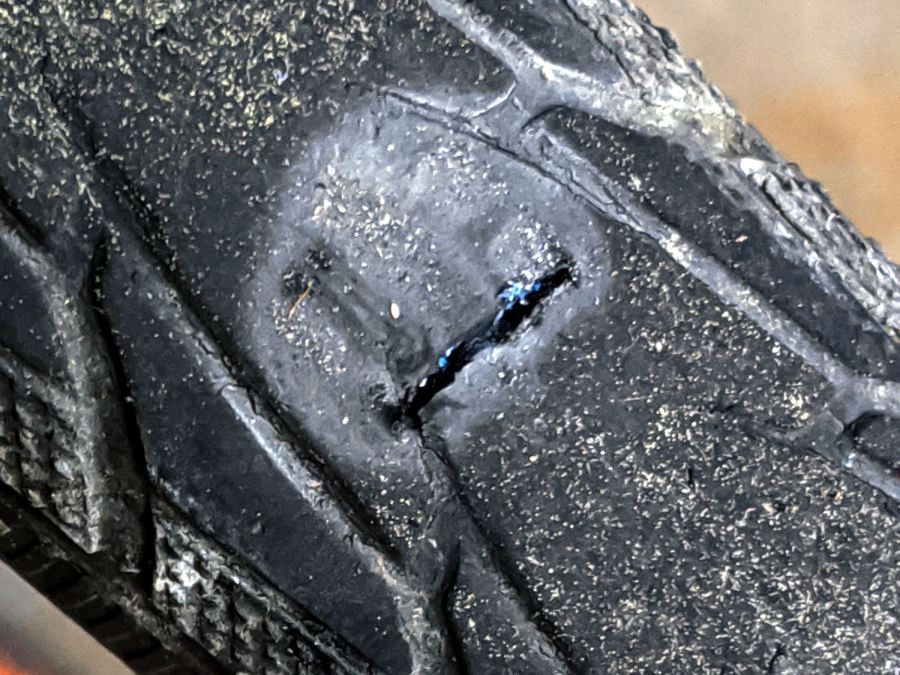
I cleaned the wound, filled it with silicone rubber, topped it with some duct tape, and it’s still holding air after a 13 mile ride. I think the gash cut through the rubber tread and SmartGuard layer, but didn’t affect the cords in the tire carcass, so keeping further road debris out of the gash should let the tire wear out more-or-less normally.
Putting duct tape on the tread will certainly help …
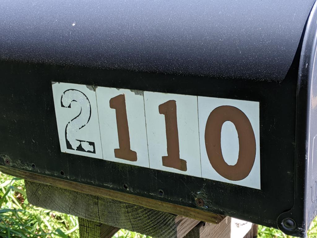
Five years later, the digits I painted with Rust-Oleum Rusty Metal Primer have weathered pretty well, while the original ink has fallen off the retroreflective sticker:
Mailbox numbers – original vs primer
As before, I wiped off the crud with denatured alcohol and painted neatly inside the lines. The other digits on both sides still look as good as the day I painted them, with only a few bubbles and nicks.
Memo to self: Next time, buy a big sheet of 3M retroreflective film, make a stencil by vinyl cutting, paint the entire number in one shot, and be done with it.
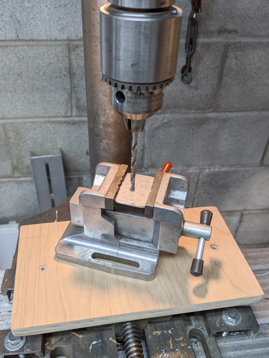
I built a small plywood work table for the drill press:
Drill press – scarred vise table
Obviously, that was a long time ago. It’s a plywood scrap with a small cleat screwed to its bottom, upon which one can position / clamp / hold / finagle smallish workpieces without worrying about drilling into the surface.
The mill vise under the plywood grips the cleat and the whole affair rides on a Sears “Drill Press Milling Attachment Stock No 27585” which is basically a simple XY table with hand dials. It’s not rigid enough for actual milling (which you should never do on a drill press, anyway, because the end mill will pull itself out of the Jacobs chuck), but it’s good for tweaking the position before you drill something.
One should never hand-hold workpieces while drilling.
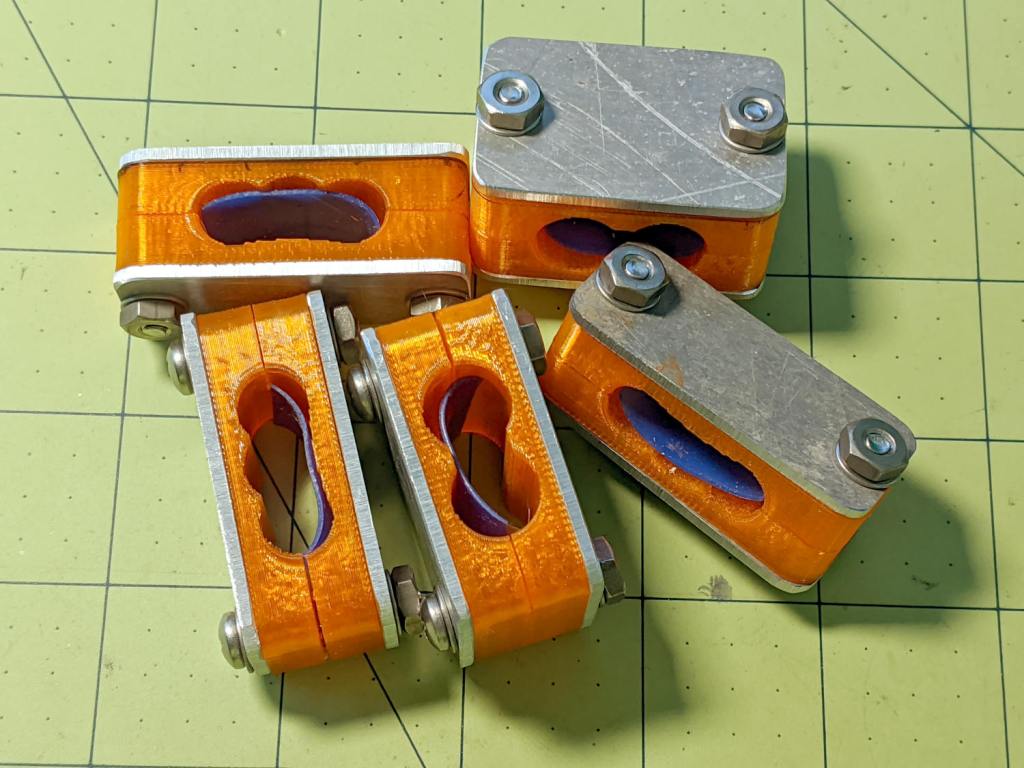
Actually, those are the remainder of two production runs devoted to reducing the amount of water sprinkling the garden paths. A 50 foot hose runs along both sides of one 14 foot bed, crosses the path, then continues along the adjacent bed. The hoses have (deliberate!) sprinkler holes along their porous rubber body and sometimes the layout puts a hole where it waters the path.
The blue silicone rubber strips provide a bit of sealing to prevent the absurdly high pressure water from streaming through the orange PETG clamps. It’s OK if the clamp leaks, but less flow is better!
I’m getting really good at making those aluminum backing plates and, in fact, I think it’s faster to run the blanks past the disk sander, then drill the holes, than to CNC-machine them. Could be wrong, but Quality Shop Time is not to be sniffed at.