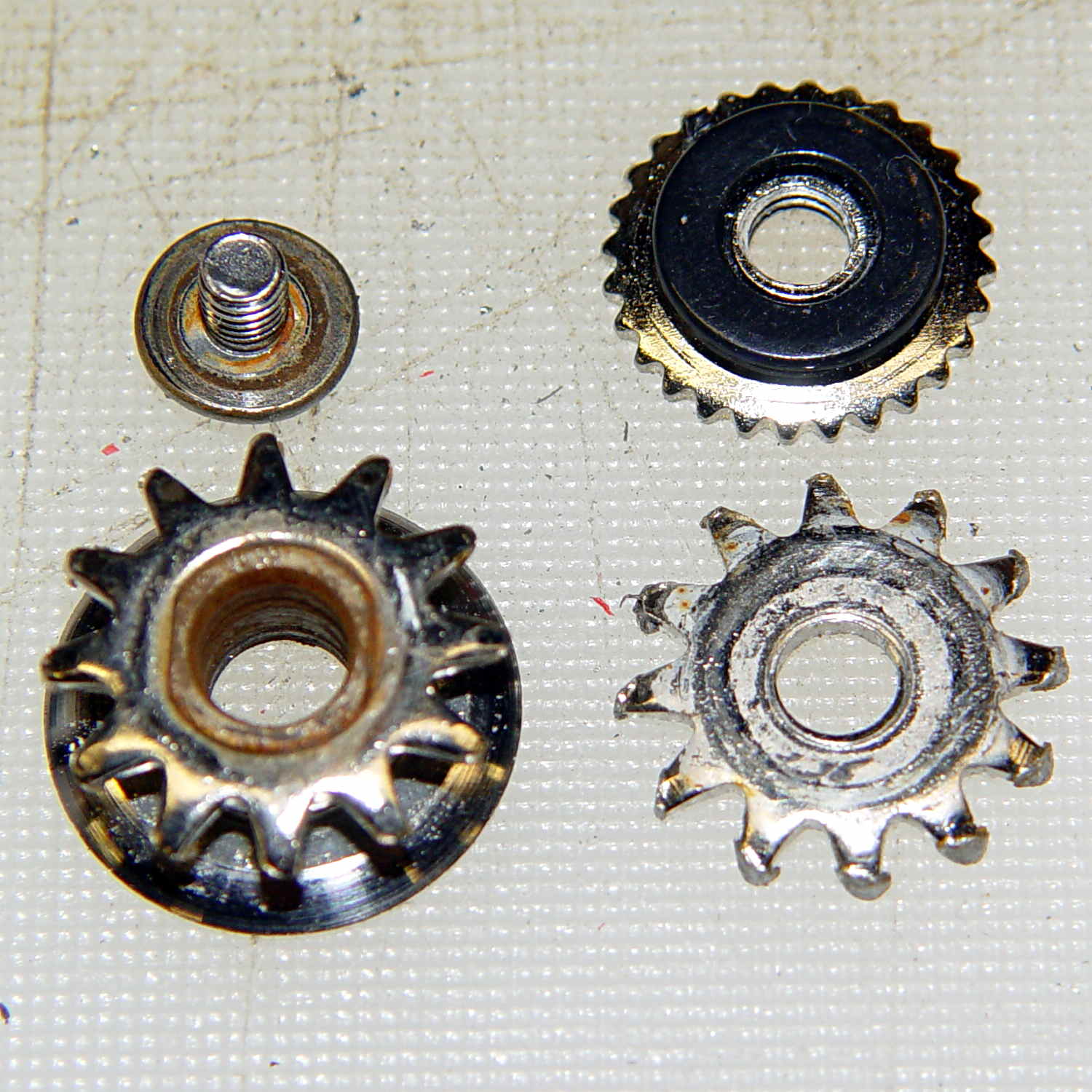
Cleaning up the wrecked gears on the can opener made it painfully obvious that I had to conjure at least one gear to get the poor thing working again:
Fortunately, those are more in the line of cogs, rather than real gears, so I decided a crude hack would suffice: drill a pattern of holes to define the openings between the teeth, file / grind the teeth reasonably smooth, and then tweak the shape to suit.
Fitting some small number-size drills between the remains of the teeth showed:
- A #52 = 52.0 mil = 1.32 mm drill matched the root curvature
- A #28 = 140.5 mil = 3.57 mm drill was tangent to the small drill and the tooth walls
Neither of those count as precision measurements, particularly given the ruined teeth, but they’re close enough for a first pass.
The OEM drive gear (on the right) has the teeth bent upward to mate with the cutter gear (on the left), but under normal gripping force, the teeth don’t mesh securely and tend to slide over / under / past each other. However, if I were to cut the drive gear from a metal sheet that’s thick enough to engage both the root and the crest of the cutter gear, that should prevent all the slipping & sliding. Some eyeballometric guesstimation suggested 2.5 mm would be about right and the Basement Laboratory Stockpile produced a small slab of 100 mil = 2.54 mm aluminum sheet.
However, the center part of the gear must have the same thickness as the OEM gear to keep the drive wheel at the same position relative to the cutter blade, which means a bit of pocket milling. I have some small ball burrs that seemed like they might come in handy.
A recent thread on the LinuxCNC mailing list announced Bertho Stultien’s gcmc, the G-Code Meta Compiler, and this looked like a golden opportunity to try it out. Basically, gcmc lets you write G-Code programs in a C-like language that eliminates nearly all the horrendous syntactic noise of raw G-Code. I like it a lot and you’ll be seeing more of it around here…
The gcmc source code, down below, include a function that handles automatic tool height probing, using that simple white-goods switch. The literal() function emits whatever you hand it as text for the G-Code file, which is how you mechanize esoteric commands that gcmc doesn’t include in its repertoire. It’s basically the same as my bare G-Code probe routine, but now maintains a state variable that eliminates the need for separate first-probe and subsequent-probe entry points.
One point that tripped me up, even though I should know better: because gcmc is a compiler, it can’t read G-Code parameters that exist only when LinuxCNC (or whatever) is interpreting the G-Code. You can write parameters with values computed at compile time, but you can’t read and process them in the gcmc program.
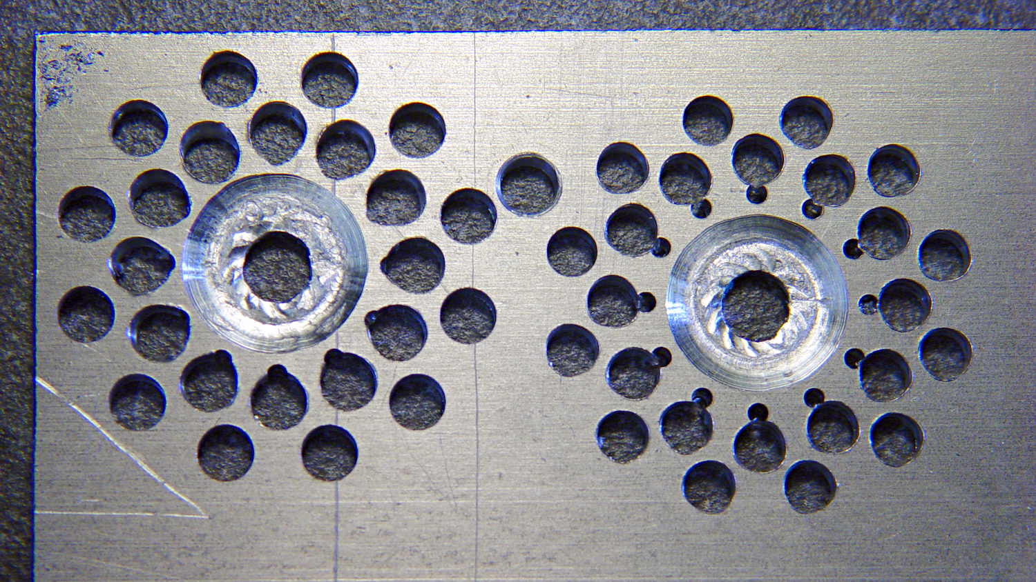
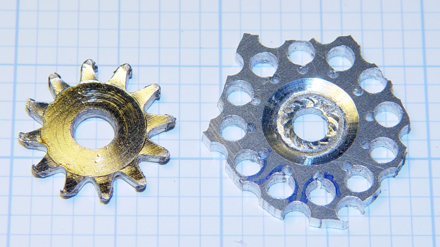
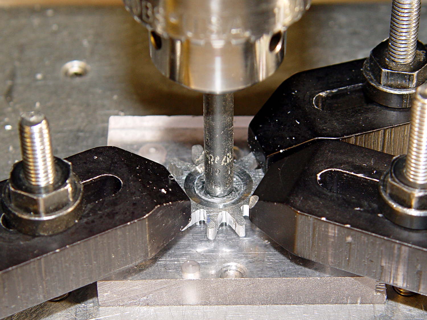
Anyhow, the first pass produced an array of holes that, as I fully expected, weren’t quite right:
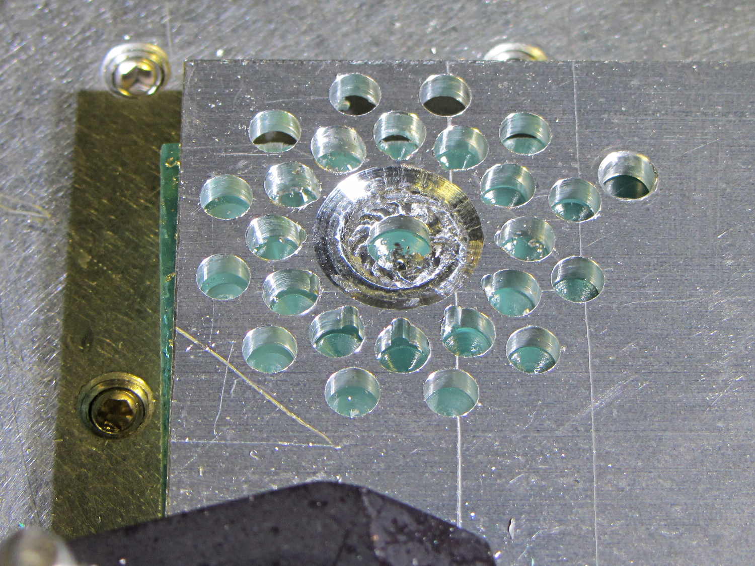
The second pass got the root and middle holes tangent to each other:
It also ran a center drill pass for those tiny little holes to prevent their drill from wandering about. The other drills are about the same size as the center drill, so they’re on their own.
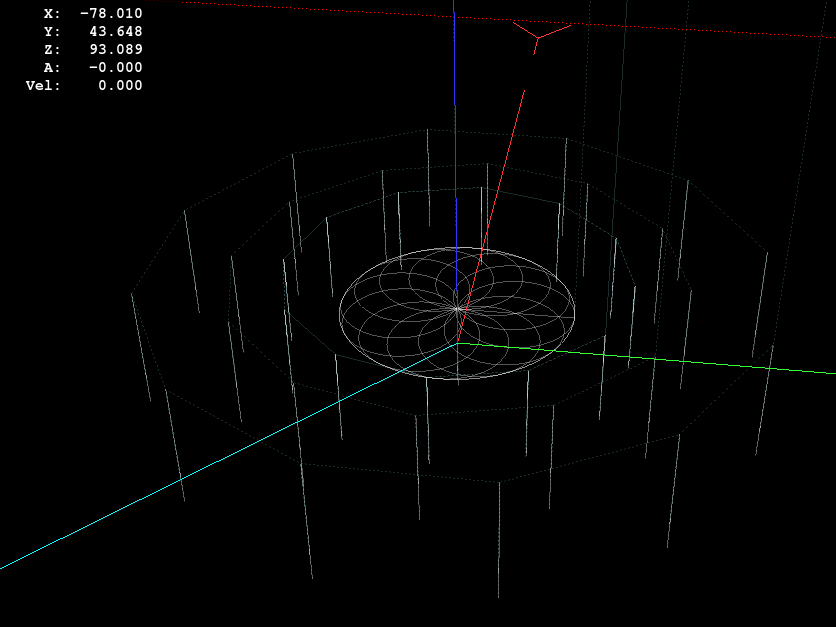
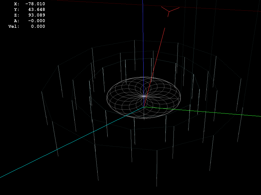
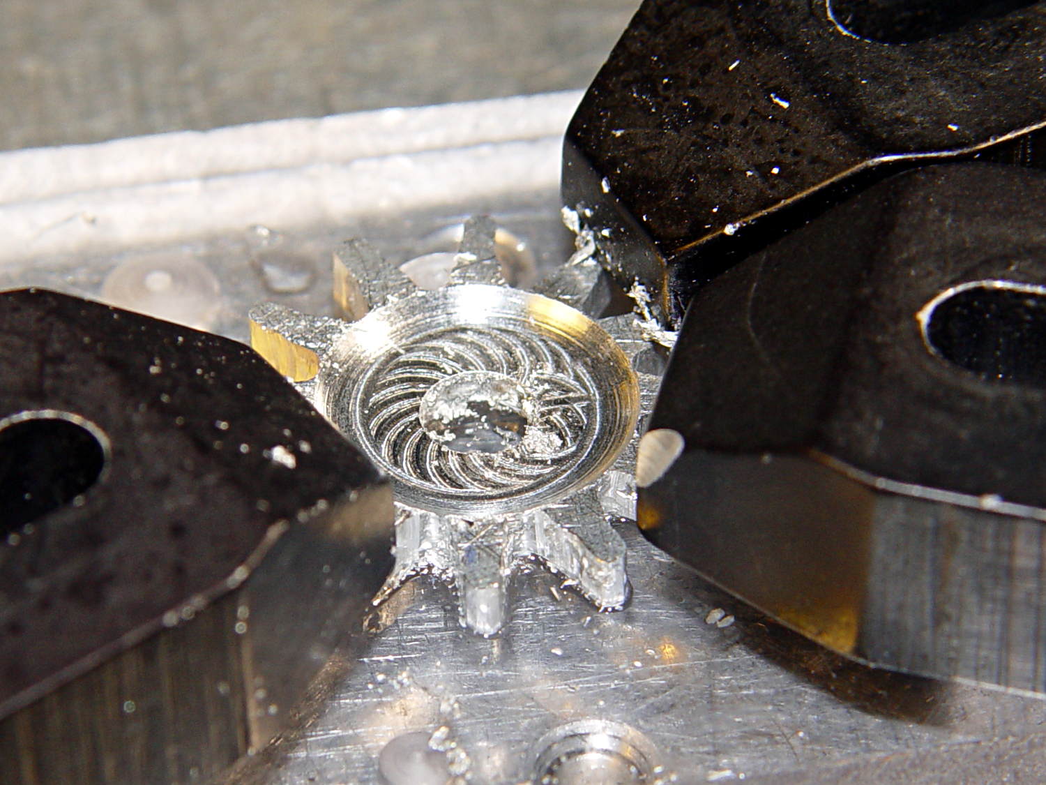
The rosette around the central hole comes from sweeping the burr in a dozen overlapping circles tangent to the outer diameter, then making a cleanup pass around the OD:
Incidentally, that stray hole between the two patterns came from the aluminum sheet’s previous life, whatever it may have been. There are three other holes, two of which had flat washers taped to them, so your guess is as good as mine. That’s my story and I’m sticking with it.
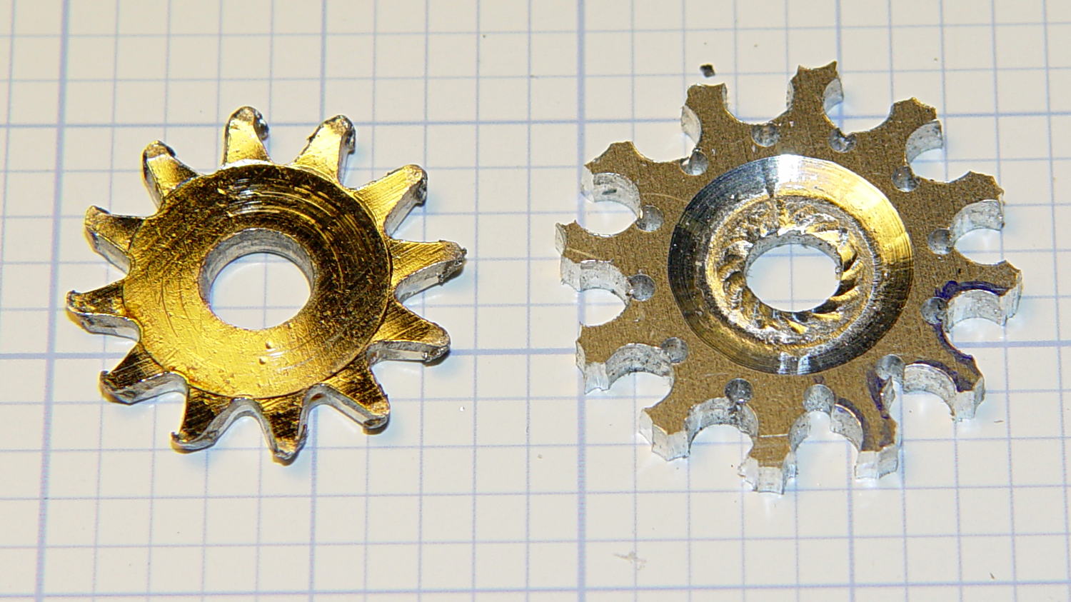
Introducing the sheet to Mr Bandsaw and cutting through the outer ring produced a bizarre snowflake:
Cutting off the outer ring of holes turned the incipient gear body into a ragged shuriken:
A few minutes of increasingly deft Dremel cutoff wheel work, poised on the bench vise over the shopvac nozzle to capture the dust, produced a credible gear shape:
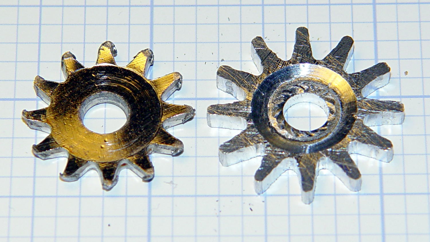
Iterating through some trial fits, re-grinds, and general fiddling showed that the center pocket was too shallow. The cutter wheel should slightly clear the drive wheel, but it’s an interference fit:
Which, of course, meant that I had to clamp the [mumble] thing back in the Sherline and re-mill the pocket. The trick is to impale it on the wrong end of a suitable drill, clamp it down, and touch off that spot as the origin:
I took the opportunity to switch to a smaller ball and make 16 little circles to clear the pocket:
Now that’s better:
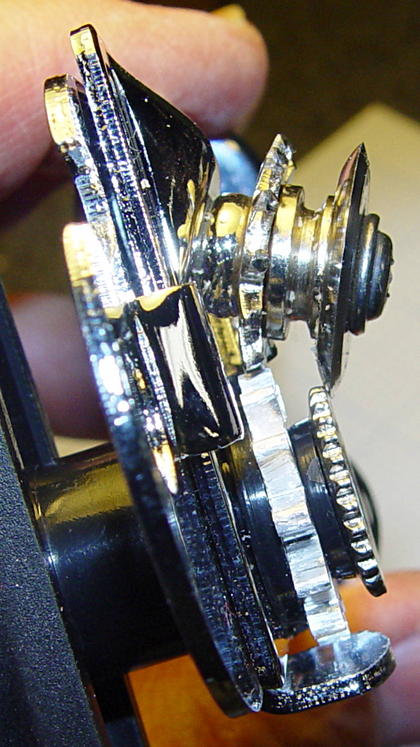
Another trial fit showed that everything ended up in the right place:
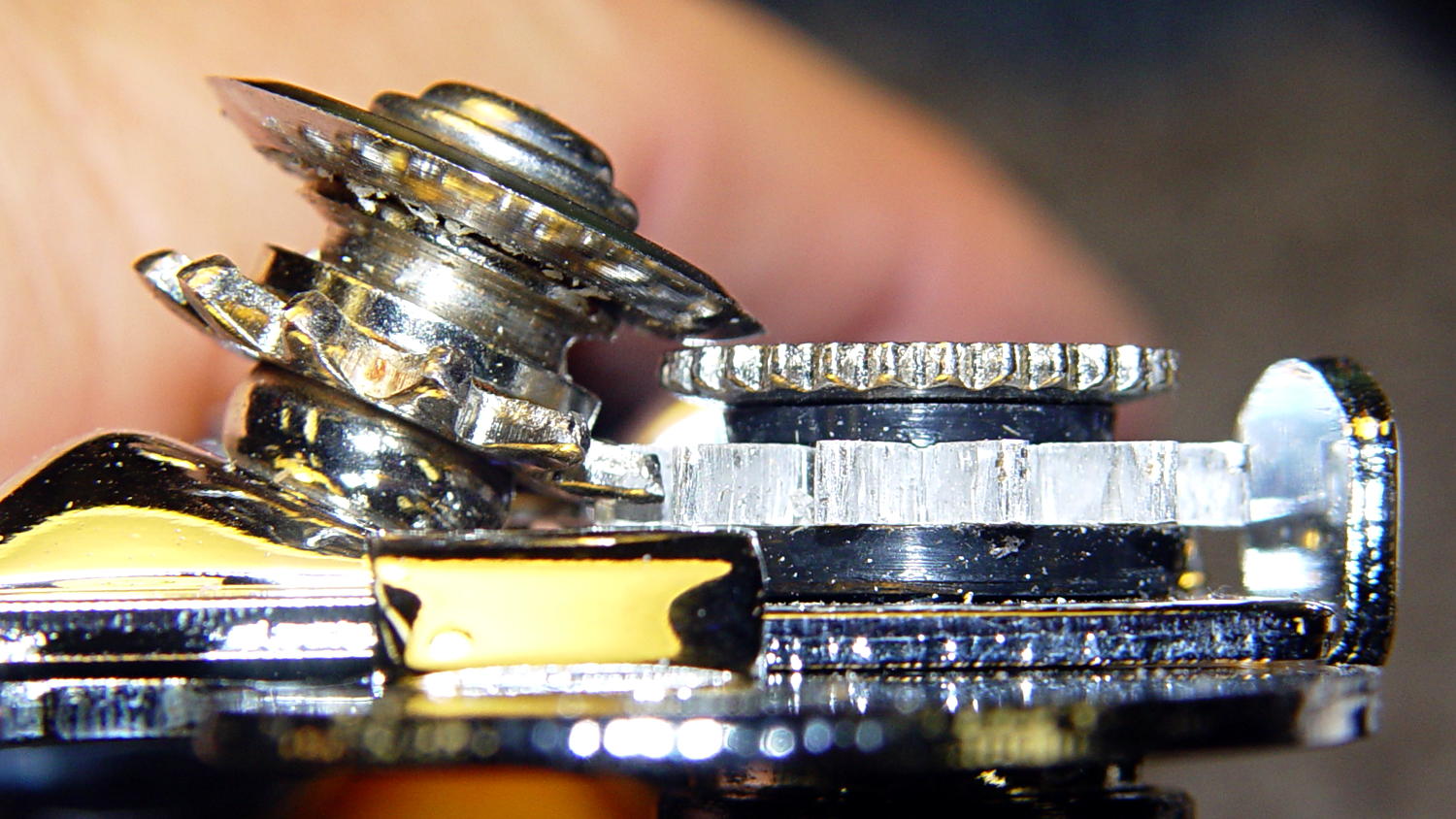
I gave it a few cranks, touched up any cogs that clashed with the (still misshapen) cutter gear, applied it to a randomly chosen can, and it worked perfectly:
- Squeeze the levers to easily punch through the lid
- Crankety crank on the handle, while experiencing none of the previous drama
- The severed lid falls into the can
Which is exactly how it’s supposed to work. What’s so hard about that?
What you can’t see in that picture is the crest of the lowest cutter gear tooth fitting just above the bottom of the drive gear root. Similarly, the crest of the highest drive gear tooth remains slightly above the cutter root. That means the cutter gear teeth always engage the drive gear, there’s no slipping & sliding, and it’s all good.
Aluminum isn’t the right material for a gear-like object meshed with a steel counterpart, but it’s easy to machine on a Sherline. I’ll run off a few more for show-n-tell and, if when this one fails, I’ll have backup.
The gcmc source code:
// Can opener drive gears
//	Ed Nisley KE4ZNU - February 2014
//	Sherline CNC mill with tool height probe
//	XYZ touchoff origin at center on fixture surface

DO_DRILLCENTER	= 1;
DO_MILLCENTER	= 1;
DO_DRILLINNER	= 1;
DO_DRILLOUTER	= 1;
DO_DRILLTIPS	= 1;

//----------
// Overall dimensions

GearThick = 2.54;			// overall gear thickness
GearCenterThick = 1.75;		// thickness of gear center

GearTeeth = 12;				// number of teeth!
ToothAngle = 360deg/GearTeeth;
GearOD = 22.0;				// tooth tip
GearID = 13.25;				// tooth root

SafeZ = 20.0;				// guaranteed to clear clamps
TravelZ = GearThick + 1.0;	// guaranteed to clear plate

//----------
// Tool height probe
//	Sets G43.1 tool offset in G-Code, so our Z=0 coordinate always indicates the touchoff position

ProbeInit = 0;					// 0 = not initialized, 1 = initialized
ProbeSpeed = 400.0mm;
ProbeRetract = 1.0mm;

PROBE_STAY = 0;					// remain at probe station
PROBE_RESTORE = 1;				// return to previous location after probe

function ProbeTool(RestorePos) {

local WhereWasI;

	WhereWasI = position();

	if (ProbeInit == 0) {		// probe with existing tool to set Z=0 as touched off
		ProbeInit++;
		literal("#<_Probe_Speed> = ",to_none(ProbeSpeed),"\n");
		literal("#<_Probe_Retract> = ",to_none(ProbeRetract),"\n");
		literal("#<_ToolRefZ> = 0.0 \t; prepare for first probe\n");
		ProbeTool(PROBE_STAY);
		literal("#<_ToolRefZ> = #5063 \t; save touchoff probe point\n");
		literal("G43.1 Z0.0 \t; set zero offset = initial touchoff\n");
	}
	elif (ProbeInit == 1) {		// probe with new tool, adjust offset accordingly
		literal("G49 \t; clear tool length comp\n");
		literal("G30 \t; move over probe switch\n");
		literal("G59.3 \t; use coord system 9\n");
		literal("G38.2 Z0 F#<_Probe_Speed> \t; trip switch on the way down\n");
		literal("G0 Z[#5063 + #<_Probe_Retract>] \t; back off the switch\n");
		literal("G38.2 Z0 F[#<_Probe_Speed> / 10] \t; trip switch slowly\n");
		literal("#<_ToolZ> = #5063 \t; save new tool length\n");
		literal("G43.1 Z[#<_ToolZ> - #<_ToolRefZ>] \t; set new length\n");
		literal("G54 \t; return to coord system 0\n");
		literal("G30 \t; return to safe level\n");
	}
	else {
		error("*** ProbeTool sees invalid ProbeInit: ",ProbeInit);
		comment("debug,*** ProbeTool sees invalid ProbeInit: ",ProbeInit);
		ProbeInit = 0;
	}

	if (RestorePos == PROBE_RESTORE) {
		goto(WhereWasI);
	}

}

//----------
// Utility functions

function WaitForContinue(MsgStr) {
	comment(MsgStr);
	pause();
}

function CueToolChange(MsgStr) {
	literal("G0 Z" + SafeZ + "\n");
	literal("G30\n");
	WaitForContinue(MsgStr);
}

function ToolChange(Info,Name) {
	CueToolChange("msg,Insert " + to_mm(Info[TOOL_DIA]) + " = " + to_in(Info[TOOL_DIA]) + " " + Name);
	ProbeTool(PROBE_STAY);

	WaitForContinue("msg,Set spindle to " + Info[TOOL_SPEED] + " rpm");
	feedrate(Info[TOOL_FEED]);
}

function GetAir() {
	goto([-,-,SafeZ]);
}

//-- compute drill speeds & feeds based on diameter
//		rule of thumb is 100 x diameter at 3000 rpm for real milling machines
//		my little Sherline's Z axis can't produce enough thrust for that!

MaxZFeed = 600.0mm;				// fastest possible Z feed

TOOL_DIA = 0;					// Indexes into DrillParam() result
TOOL_SPEED = 1;					//  spindle RPM
TOOL_FEED = 2;					//	linear feed
TOOL_TIP = 3;					//	length of 118 degreee drill tip

function DrillParam(Dia) {
local RPM,Feed,Tip,Data,Derating;

	Derating = 0.25;			// derate from (100 x diameter) max feed

	RPM = 3000.0;				// default 3 k rpm

	Feed = Derating * (100.0 * Dia);
	if (Feed > MaxZFeed) {
		RPM *= (MaxZFeed / Feed);	//  scale speed downward to fit
		Feed = MaxZFeed;
	}

	Tip = (Dia/2) * tan(90deg - 118deg/2);
	Data = [Dia,RPM,Feed,Tip];

	message("DrillParam: ",Data);
	return Data;
}

//-- peck drilling cycle

function PeckDrill(Endpt,Retract,Peck) {
	literal("G83 X",to_none(Endpt[0])," Y",to_none(Endpt[1])," Z",to_none(Endpt[2]),
			" R",to_none(Retract)," Q",to_none(Peck),"\n");
}

//----------
// Make it happen

literal("G99\t;  retract to R level, not previous Z\n");

WaitForContinue("msg,Verify: G30 position in G54 above tool change switch?");

WaitForContinue("msg,Verify: fixture origin XY touched off at center of gear?");

WaitForContinue("msg,Verify: Z touched off on top surface at " + GearThick + "?");
ProbeTool(PROBE_STAY);

//-- Drill center hole

if (DO_DRILLCENTER) {

	DrillData = DrillParam(5.0mm);
	ToolChange(DrillData,"drill");

	goto([0,0,-]);
	goto([-,-,TravelZ]);

	drill([0,0,-1.5*DrillData[TOOL_TIP]],TravelZ,DrillData[TOOL_DIA]);
	GetAir();

}

//-- Drill inner ring

if (DO_DRILLINNER) {

	DrillData = DrillParam(1.32mm);

	RingRadius = GearID/2.0 + DrillData[TOOL_DIA]/2.0;		// center of inner ring holes
	HolePosition = [RingRadius,0mm,-1.5*DrillData[TOOL_TIP]];

//	but first, center-drill to prevent drifting

	CDData = DrillParam(1.00mm);			// pretend it's a little drill
	CDData[TOOL_FEED] = 100mm;				//  ... use faster feed

	CDPosition = HolePosition;				// use center drill coordinates
	CDPosition[2] = GearThick - 0.25mm;		//  ... just below surface

	ToolChange(CDData,"center drill");

	goto([0,0,-]);
	goto([-,-,TravelZ]);

	for (Tooth = 0 ; Tooth < GearTeeth ; Tooth++) {
		drill(CDPosition,TravelZ,2*TravelZ);		// large increment ensures one stroke
		CDPosition = rotate_xy(CDPosition,ToothAngle);
	}

//	now drill the holes

	ToolChange(DrillData,"drill");

	goto([0,0,-]);
	goto([-,-,TravelZ]);

	for (Tooth = 0 ; Tooth < GearTeeth ; Tooth++) {
		PeckDrill(HolePosition,TravelZ,DrillData[TOOL_DIA]);
		HolePosition = rotate_xy(HolePosition,ToothAngle);
	}

	GetAir();

}

//-- Mill center recess

if (DO_MILLCENTER) {

	MillData = [4.50mm,3000,250.0mm,0.0mm];			// spherical ball burr

	Delta = GearThick - GearCenterThick;							// depth to be milled away
	Inset = sqrt(2.0*Delta*(MillData[TOOL_DIA]/2) - pow(Delta,2));	// toll axis to milled edge

	ToolChange(MillData,"ball burr");

	goto([0,0,-]);							// above central hole
	goto([0,0,GearThick]);					// vertically down to flush with surface
	move([0,0,GearCenterThick]);			// into gear blank

	for (Angle = 0.0deg; Angle < 360.0deg; Angle+=360.0deg/16) {	// clear interior
		circle_cw((GearID/2 - Inset)/2,Angle);
	}

	move_r([(GearID/2 - Inset),0.0,0.0]);							// clean rim
	circle_ccw([0.0,0.0,GearCenterThick],2);

	GetAir();

}

//-- Drill outer ring

if (DO_DRILLOUTER) {

	RingRadius += DrillData[TOOL_DIA]/2;		// at OD of inner ring holes

	DrillData = DrillParam(3.18mm);
	RingRadius += DrillData[TOOL_DIA]/2.0;		// center of outer ring holes
	HolePosition = [RingRadius,0mm,-1.5*DrillData[TOOL_TIP]];

	ToolChange(DrillData,"drill");

	for (Tooth = 0 ; Tooth < GearTeeth ; Tooth++) {
		PeckDrill(HolePosition,TravelZ,DrillData[TOOL_DIA]);
		HolePosition = rotate_xy(HolePosition,ToothAngle);
	}

	GetAir();

}

//-- Drill to locate gear tooth tip end

if (DO_DRILLTIPS) {

	DrillData = DrillParam(4.22mm);

	RingRadius = GearOD/2.0 + DrillData[TOOL_DIA]/2.0;		// tangent to gear tooth tip
	HolePosition = [RingRadius,0mm,-1.5*DrillData[TOOL_TIP]];
	HolePosition = rotate_xy(HolePosition,ToothAngle/2);	// align to tooth

	ToolChange(DrillData,"drill");

	for (Tooth = 0 ; Tooth < GearTeeth ; Tooth++) {
		PeckDrill(HolePosition,TravelZ,DrillData[TOOL_DIA]);
		HolePosition = rotate_xy(HolePosition,ToothAngle);
	}

	GetAir();

}

literal("G30\n");
comment("msg,Done!");
The original doodle that suggested the possibility:
The chord equation at the bottom shows how to calculate the offset for the ball burr, although it turns out there’s no good way to measure the cutting diameter of the burr and it’s not really spherical anyway.
A more detailed doodle with the key line at a totally bogus angle:
The diagram in the lower right corner shows how you figure the length of the tip on a 118° drill point, which you add to the thickness of the plate in order to get a clean hole.

Comments
4 responses to “Can Opener Gear Rebuild”
Ed, Good Job! About a buck for a whole new one at Dollar Tree. :-(
Say Ed, on a 3D printer note. I’ve been trashed on a new printer Ive built. All and more that can go wrong has and more. Now, I’m able to maybe print – again from again from again …. etc…. Anyway, I can’t think anymore. What causes the, too much plastic, blobs in the 90° corners of cubes and the blobby infill bends? I’ve switched from our old MakerBot environ. to Marlin, Slic3r and Pronterface. Not that is a real big deal. I can’t remember where to target. Oh, the rest of the print is acceptable as to print size. A 20 x 20 x 10 mm cube comes out close enough. Within .1-.2 of a mm. And right now I’m printing with too little plastic because the tops and bottoms almost look like a screen…. How to address the corners?
Brian.
Pittsburgh, PA
http://www.flickr.com/photos/99814689@N00/13411166313
http://www.flickr.com/photos/99814689@N00/13411425074
http://www.flickr.com/photos/99814689@N00/13411411394
[Ed: I fixed the links. They need some text to highlight, so I used the bare URL.]
Nah, it was maybe eight bucks: we went high class on that puppy!
The top infill seems so sparse that I wonder if the extruder is producing the proper thread width. Word from the Makergear forum suggests that forcing a fixed thread width, rather than using the automatic settings, works better; I’ve always set the width, because I want to know exactly what the extruder is doing.
Perhaps the XY acceleration isn’t up to spec and the extruder continues drooling while the nozzle slows down at the corners. Is it using 3 mm or 1.75 mm filament?
It could also be grossly low extruder acceleration that prevents fast retraction, but I’d look at the XY numbers first. There shouldn’t be any retraction on the top infill, where it’s producing gross blobs, so that’s not the only problem.
I’d run off a handful of thinwall open boxes to check the width, then return to the solid boxes.
Thanks Ed –
XY accel is about 3000. I set nozzle width. Filament is 1.75. Retraction maybe slow at 45mm/s. Thin wall isn’t working too well with Slic3r now according to others and my tests. The top fill is sparse which had me lost to why the blobs… I had not this problem before. I am tuning in a newer hot end which has a much longer heat zone and has to print @ ~ 240° C. I’m shaky at this high temp. Used to 225° C being the high. Anyway —- I’ll trudge the forums now. I was just beaten with the gremlins which have burned connectors, broken wires, corrupted bootloaders, and many, many other odd things.
Take care – stay warm — its 18° F here today…
That may be the whole problem: a longer melt zone means you have much more gooey plastic and less control. High extruder acceleration (not just speed) will make retraction work better, but that won’t cure the top surface blobs; that’s the pressurized plastic oozing out while the XY slows for the corners.
More acceleration on all axes will help, although that’s constrained by the mechanics: just screw on as much as you can and see if the blobs shrink.