The Smell of Molten Projects in the Morning

Ed Nisley's Blog: Shop notes, electronics, firmware, machinery, 3D printing, laser cuttery, and curiosities. Contents: 100% human thinking, 0% AI slop.

Tag: Repairs

If it used to work, it can work again

  • M2 Nozzle Clog: FOD

    M2 Nozzle Clog: FOD

    This happened while switching from natural to black PETG:
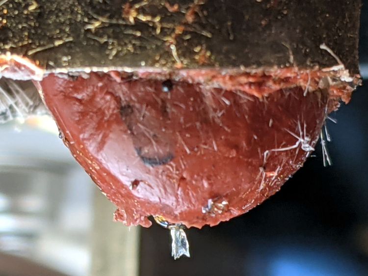
    M2 nozzle clog - exterior
    M2 nozzle clog – exterior

    A closer look:

    M2 nozzle clog - exterior detail
    M2 nozzle clog – exterior detail

    Those pix happened after trying to extract whatever-it-is with tweezers, so it’s definitely something with a higher melting point than PETG.

    Removing the (warm) nozzle with the block held in a vise reveals a tuft of something:

    M2 nozzle clog - interior
    M2 nozzle clog – interior

    The tuft accumulated several turns while unthreading the nozzle from the hot end.

    Heating the nozzle a bit more released the tuft:

    M2 nozzle clog - extracted tuft
    M2 nozzle clog – extracted tuft

    The black-to-clear transition tailing off at the bottom came from the PETG around the tuft in the cone-shaped end of the nozzle above the aperture. The 100 mil squares suggest the tuft was a distinct entity, rather than a collection of threads, and might have been over 5 mm long.

    Perhaps a fragment of PTFE or another high-melting-point plastic?

    Reassemble in reverse order, reset the nozzle to Z=0 on the platform, and it’s all good.

  • Miniblind Mounting Brackets: Version 4

    Miniblind Mounting Brackets: Version 4

    Miniblinds don’t last forever:

    Miniblind failure
    Miniblind failure

    The plastic frame failed at the pull cord opening, obviously a weak and, alas, non-repairable point.

    A quick trip to Lowe’s produced a new miniblind with mounting hardware completely different from the old one. This came as no surprise, as every new miniblind differs from all previous ones; miniblind mounting hardware is not strongly conserved.

    The broken frame fit into the plastic end caps mounted just beyond the scarred paint marking the bracket location required for the previous miniblind:

    Miniblind bracket - V3
    Miniblind bracket – V3

    Note that the caps mount with a single screw in the homebrew bracket’s face, which has two holes to match the previous-previous cap.

    Also note how the curved moulding strips around the 1955-era windows in this house do not fit any contemporary miniblind hardware, thus requiring Quality Shop Time with every installation.

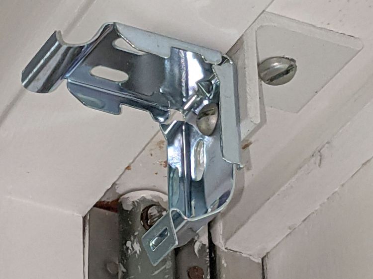
    Although the shiny new hardware had two slots, they neither lined up with the existing bracket holes nor extended quite far enough vertically. I lined things up, marked and drilled a single midline hole in both the new hardware and the old bracket, and reused the old screw and nut:

    Miniblind bracket - V4 side
    Miniblind bracket – V4 side

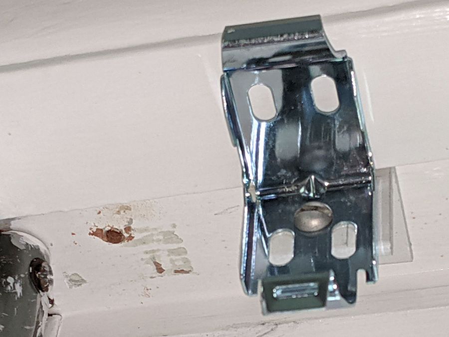
    Moving the bracket back to its previous-previous location exposed the scarred paint under the previous position:

    Miniblind bracket - V4 front
    Miniblind bracket – V4 front

    Fortunately, it’s hidden by the installed miniblind.

    That was, all things considered, easy …

  • Sherline Tooling Plate Re-Alignment

    Sherline Tooling Plate Re-Alignment

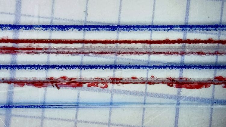
    Engraving a 0.2 mm deep hairline in a Tek Circuit Computer cursor showed the fixture had a bit of a tilt:

    Hairline V tool - 0.2 0.3 0.4 DOC 10K RPM - water cool mid
    Hairline V tool – 0.2 0.3 0.4 DOC 10K RPM – water cool mid

    The bottom blue hairline started with a good cut and ended with the V tool skating along the surface without cutting. The raggedy red one just above it is what happens when you (well, I) try engraving a hairline through Kapton tape without coolant; just don’t do that thing.

    The 3D printed fixture holding the cursor came from a neurotically aligned Makergear M2 and the tooling plate has never had much attention to its alignment, so I figured the tilt probably came from crud between the tooling plate and the Sherline’s X axis table, with the printed fixture contributing zilch to the problem.

    Which turned out to be the case. Scraping a few flakes from the bottom of the plate and top of the table, dissolving old crud with water + alcohol, and passing a file over both surfaces definitely made a difference. I converted a sheet of 0.1 mm laminating plastic film into a pad by punching holes for the T-nuts:

    Sherline tooling plate pad
    Sherline tooling plate pad

    Snugging the tooling plate down produced perfect alignment along the length of three 0.3 mm deep hairlines:

    Hairline V tool tests - 0.3 mm 10 kRPM 24 ipm
    Hairline V tool tests – 0.3 mm 10 kRPM 24 ipm

    That was surprisingly easy …

  • Kenmore Dryer Temperature Selector Puzzle

    Kenmore Dryer Temperature Selector Puzzle

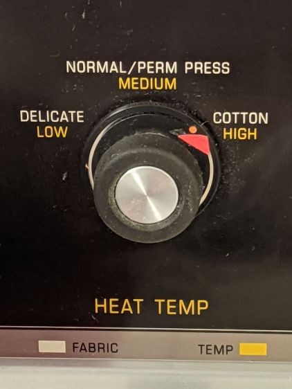
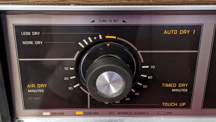
    On rare occasions, our longsuffering and much-repaired Kenmore clothes dryer will sometimes not fully dry a load, as if the heater didn’t turn on. Setting the temperature selector to High:

    Kenmore dryer temperature selector - front panel
    Kenmore dryer temperature selector – front panel

    Then resetting the cycle timer to the spot marked with the otherwise unlabeled asterisk to activate the humidity sensor gets the job done:

    Kenmore dryer cycle select dial
    Kenmore dryer cycle select dial

    We normally crank the knob to the asterisk, leave the temperature set to Normal, and mostly it works.

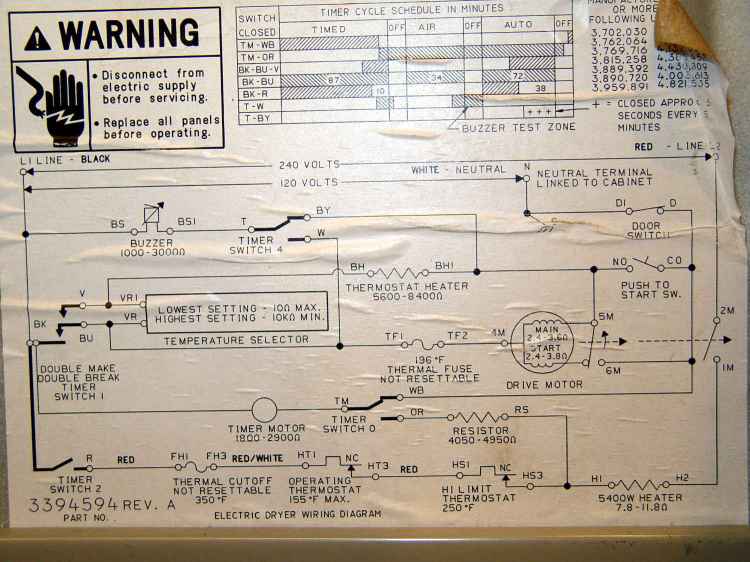
    After perusing the wiring diagram:

    Kenmore clothes dryer 110.96282100 - wiring diagram
    Kenmore clothes dryer 110.96282100 – wiring diagram

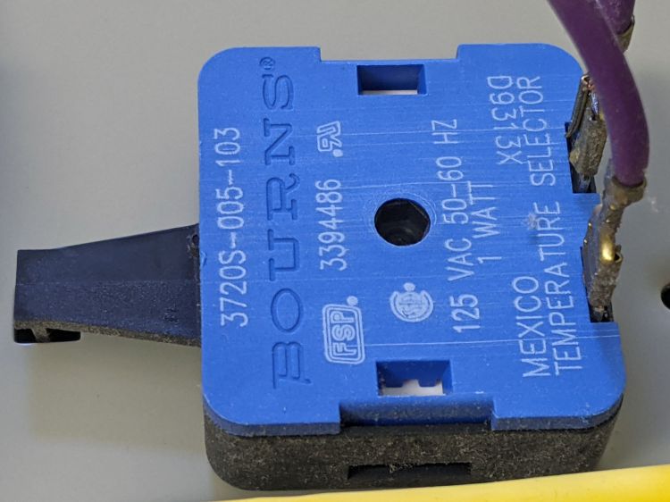
    I thought perhaps the temperature selector had become intermittent, along the lines of the temperature control knob on the oven, so I turned off the breaker, verified the dryer was disconnected, and popped the top:

    Kenmore dryer temperature selector - part detail
    Kenmore dryer temperature selector – part detail

    It turns out that part is no longer available from any of the usual sources; one describes their inventory as both “used” and “out of stock”; if it’s dead, a resurrection will be in order.

    The selector knob has three positions:

    • Low = 0 Ω, as in a closed switch
    • Medium = 5.8 kΩ, most likely a fixed resistor
    • High = open circuit, as in an open switch

    The Low and High positions meet the limits shown in the diagram and Medium falls in between, so it seems to be working as designed. If it intermittently fails as a short, then the clothes would get Low heat and (I think) would emerge somewhat more dry than we notice.

    I put it all back together, but we won’t know for a while if my laying-on-of-hands non-repair had any effect.

    One terrifying possibility, which we reject out of hand, is that we occasionally forget to crank the cycle knob around to the asterisk before punching the Start button. That would explain all the observed facts and contradict none, but is inconceivable.

  • Bypass Lopper Bumper

    Bypass Lopper Bumper

    I used the long-handled bypass lopper to harvest the 3D printed soaker hose splices and clamps, which made the sad state of the lopper’s bumper painfully obvious:

    Bypass Lopper - OEM bumper
    Bypass Lopper – OEM bumper

    Contrary to what you might think, those rivets never had a head on this side and the bumper seems to be held in place by an interference fit with the plastic handle cover.

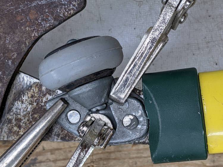
    A bit of cutoff wheel work removed the crimped end on the 5 mm stud holding the bumper to the pot-metal dingus:

    Bypass Lopper - shaft cut
    Bypass Lopper – shaft cut

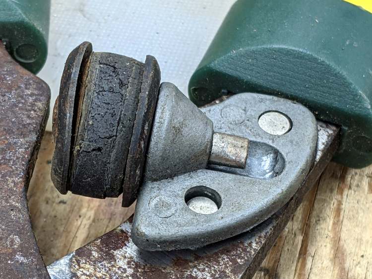
    Whacking it with a punch separated all the parts:

    Bypass Lopper - bumper parts
    Bypass Lopper – bumper parts

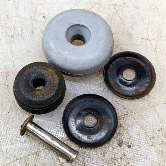
    The gray thing is a silicone rubber vibration isolator that’s a bit too large in all dimensions, but surely Close Enough™ for present purposes.

    A length of 5 mm shaft became the new stud, with M3×0.5 threads tapped into both ends and a pair of random screws held in place with red Loctite:

    Bypass Lopper - epoxy curing
    Bypass Lopper – epoxy curing

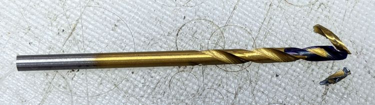
    There are no pix of the drilling and threading, as it was accomplished after a shiny-new 2.7 mm “titanium” metric drill from a not-dirt-cheap set shattered in the shaft:

    Shattered metric drill
    Shattered metric drill

    The blue color on the flutes is Sharpie to remind me it’s defunct. I completed the mission using a #36 drill with no further excitement.

    The dingus is now held to the lopper with JB Weld and, should that fail, I’ll drill-n-tap the rivets and be done with it.

  • Thermal Laminator Un-jamming

    Thermal Laminator Un-jamming

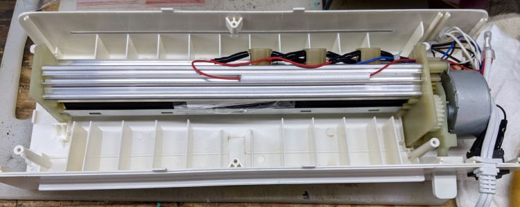
    My AmazonBasics laminator wrapped a small card around one of its rollers and jammed solid:

    AmazonBasics laminator - interior bottom
    AmazonBasics laminator – interior bottom

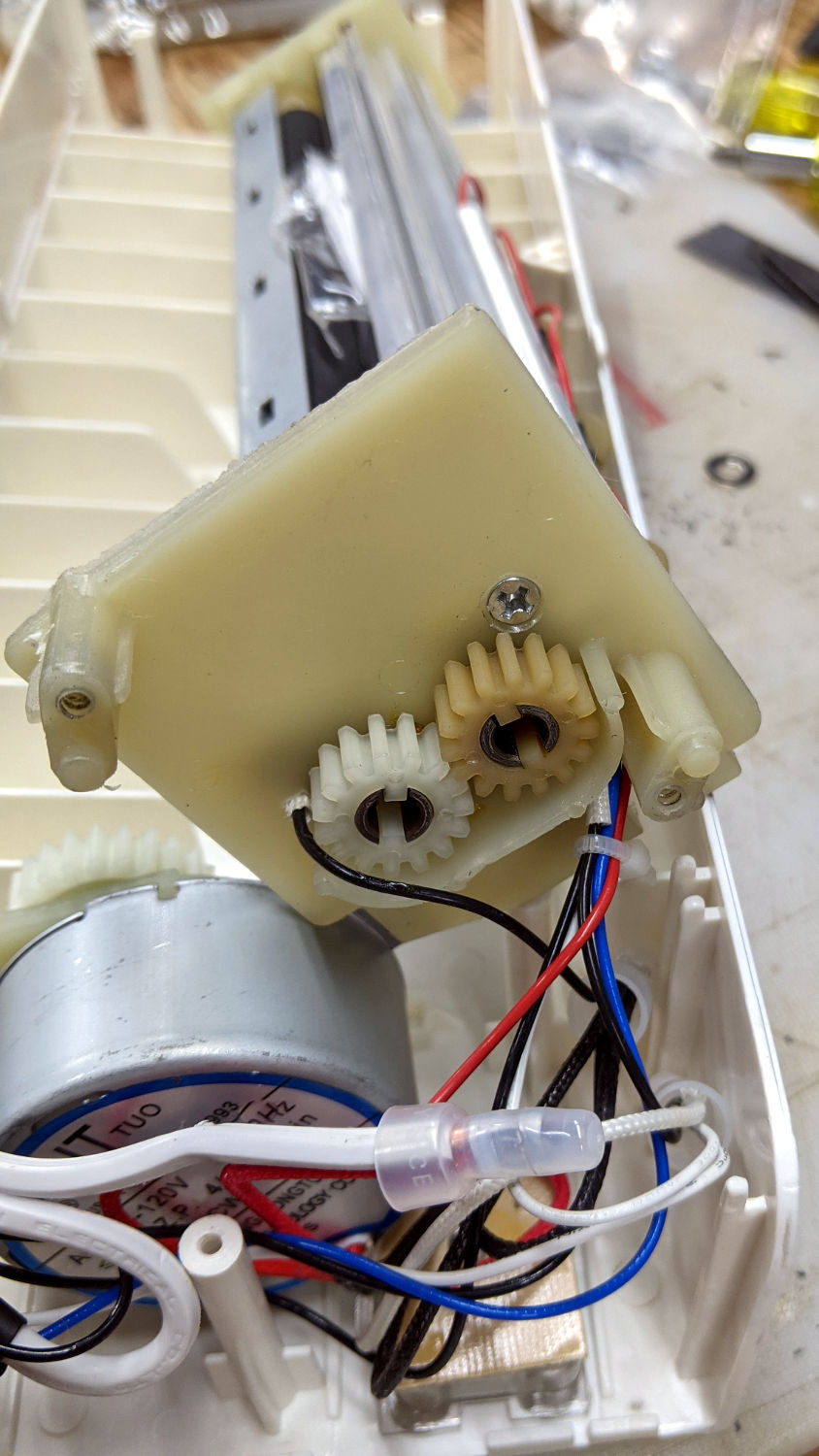
    The lever sticking out on the lower right (above) drives the rollers in reverse by moving the motor from one gear to the other:

    AmazonBasics laminator - roller gears
    AmazonBasics laminator – roller gears

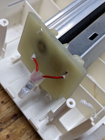
    Obviously, reverse gear wouldn’t get me anywhere, but dismantling the rollers required cutting the junction between the heating elements running through the aluminum extrusions:

    AmazonBasics laminator - heater junction
    AmazonBasics laminator – heater junction

    I spliced a few inches of wire onto those leads. If there’s a next time, I can cut the splice in the middle and use a wire nut.

    The white plastic curl in the lower right showed they ran a deburring tool around the exit slot and called it Good Enough™.

    The gears slide off the roller shafts and the rollers out of the extrusions, after which removing the tightly wrapped and completely useless card posed no problem.

    One lone, short, and eagerly self-tapping screw holds each plastic end plate to the extrusion, so be careful about cross-threading.

    All in all, this was easy enough, although I’m sure I was supposed to just throw the laminator away and buy a new one.

    Update: If you dislodged some of the wires, a few more pix of the interior may come in handy.

  • Tour Easy Rear Fender Bracket: More Cable Clearance

    Tour Easy Rear Fender Bracket: More Cable Clearance

    Most likely due to the fiddling around the larger rear brake noodle, the 3D printed bracket holding the fender to the frame failed:

    Tour Easy Rear Fender Bracket - failed joint
    Tour Easy Rear Fender Bracket – failed joint

    Hey, it lasted for six years.

    Making another one just like the other one, but with a little more clearance for the brake cable fittings, required a few tweaks to the solid model:

    Rear Fender Bracket - more clearance
    Rear Fender Bracket – more clearance

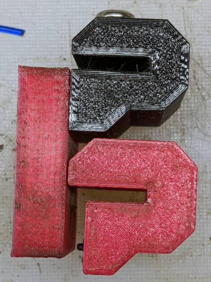
    It’s slightly less chunky and holds the fender a bit closer to the tire:

    Tour Easy Rear Fender Bracket - new vs old clearance
    Tour Easy Rear Fender Bracket – new vs old clearance

    The piece over on the left cupping the fender wasn’t broken, so I scuffed up the mating surfaces, applied a layer of JB Plastic Bonder (my new go-to adhesive for printed stuff), clamped it overnight, and it looked OK.

    While that was curing, I shortened the screw holding the clamp to the bike frame:

    Tour Easy Rear Fender Bracket - cutoff wheel dust collection
    Tour Easy Rear Fender Bracket – cutoff wheel dust collection

    The shop vac nozzle does a great job of collecting all the abrasive dust; highly recommended.

    Because I had a dollop of adhesive left over, I applied a 1.8 mm drill (from a set of metric bits I’d been meaning to buy for far too long) to the screw:

    Tour Easy Rear Fender Bracket - screw drilling
    Tour Easy Rear Fender Bracket – screw drilling

    And glued a snippet of pretty blue PETG filament in the hole:

    Tour Easy Rear Fender Bracket - frame screw PETG insert
    Tour Easy Rear Fender Bracket – frame screw PETG insert

    As far as I can tell, this will have no effect on the screw’s goodness, but it makes me feel better about crunching it onto the frame.

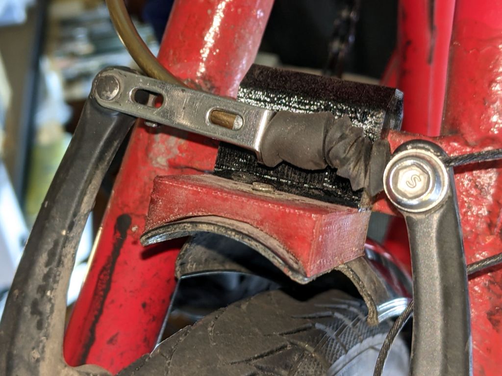
    Installation goes like you’d expect and there’s now enough clearance to keep the brake hardware off the bracket:

    Tour Easy Rear Fender Bracket - installed
    Tour Easy Rear Fender Bracket – installed

    I replaced the boot while installing the larger noodle; perhaps I should have trimmed most of it away.

    The riding season is upon us!