Ed Nisley's Blog: Shop notes, electronics, firmware, machinery, 3D printing, laser cuttery, and curiosities. Contents: 100% human thinking, 0% AI slop.
The thumb roller fell off my digital caliper in the heat of a project, forcing me to deploy a hot backup from the upstairs desk.
This looks like a clear-cut case of underdesign, because it broke exactly where you’d expect: at the midpoint of the arch. Having my thumb right over the spot marked X, though, meant that I had all the pieces and could, at least in principle, glue everything back together.
Glued and clamped
As with all repairs involving adhesives, the real problem is clamping the parts together while the glue cures. I clamped a stack of random plastic sheets to the back of the case to establish a plane surface behind the mount, with a small steel shim to prevent the top sheet from becoming one with the repair.
The roller shaft was about the same size as a #33 drill and the opening was about 110 mils. Some 3/32″ (actually about 96 mils) rectangular telescoping brass tubing was about the right size & shape to hold the opening in alignment. Another length of tubing kept the broken part from sliding to the left.
A dab of solvent glue (I still use Plastruct, but it’s not like it used to be before it became less toxic) on both pieces, line ’em up, apply a clamp to hold it in place, and let it cure overnight.
I have no confidence that this will stay together for very long, so I’ll probably be forced to mill a little replacement mounting doodad.
Ought to be good for a few hours of quality shop time…
Memo to Self: Don’t run the slide off the end of the body, because that rubber boot is an absolute mumble to put back in place.
The Axis user interface for EMC2 has a manual command entry mode, wherein you can type G-Code statements and EMC2 will do exactly what you say. That’s handy for positioning to exact coordinates, but I rarely use it for actual machining, as it’s just too easy to mis-type a command and plow a trench through the clamps.
OK, on a Sherline mini-mill, you’d maybe just snap off a carbide end mill, but you get the general idea.
I was making a simple front panel from some ancient nubbly coated aluminum sheet. The LCD and power switch rectangles went swimmingly.
Then I tried to mill an oval for the test prod wires using G42.1 cutter diameter compensation. I did a trial run 1 mm above the surface, figured out how to make it do what I wanted, then punched the cutter through the sheet at the center of the oval and entered (what I thought were) the same commands by picking them from the history list.
EMC2 now handles concave corners by automagically inserting fillets, so it must run one command behind your typing. I drove the cutter to the upper-right end of the oval (no motion) so it could engage cutter comp mode, entered the G2 right endcap arc to the lower edge (cuts straight to upper right), and then did something wrong with the next command.
Epoxy-patched front panel hole
The cutter carved the endcap properly, then neatly pirouetted around the end and started chewing out an arc in the other direction. Even looking at the command trace I can’t figure out what I mistyped, but as it turns out it doesn’t matter… I was using the wrong dimensions for the hole anyway.
So it’s now patched with epoxy backed up by a small square of aluminum. When it’s done curing, I’ll manually drill a pair of holes at the right coordinates, manually file out the oval, shoot a couple of coats of paint, and it’ll be OK.
Nobody will ever know!
If I recall correctly, Joe Martin of Sherline was the first person to observe that, unlike word processing programs, CNC machines lack an Undo key…
Update: Like this…
Patched panel – rear view
The shoot-a-couple-of-coats thing did not go well: a maple seed landed on the front panel. Ah, well, it’s close enough. Here’s a trial fit; the bellyband height extenders on the sides need a dab of epoxy and a shot of paint, too, but I may never get a round ‘tuit for that.
Front panel trial fit
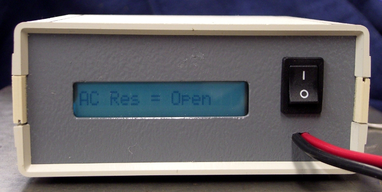
It’s the long-awaited Equivalent Series Resistance meter…
This pair of halogen outdoor spotlights has been in place for at least a decade; they don’t see much use, so the filaments haven’t burned out in all that time.
A lens fell off a few days ago, at which point I realized that it was the second lens to fall off; where the first one got to, I cannot say. I suspect they’ve never been turned on in the rain, as a single drop of water on a halogen capsule would shatter it like, uh, glass.
The right-hand bulb was evidently the first to fail, as it’s full of toasted spider silk, seed husks, and bug carapaces. The reflector aluminization doesn’t like exposure to the Great Outdoors, although it’s in surprisingly good shape for the mistreatment it’s seen.
I installed a pair of ordinary fused-glass spotlights from Ol’ Gene’s stash that Came With The House; they’ve been in the basement at least as long as those halogens have been on the side of the house. I suppose he put the good spots up there and kept the plain ones in reserve.
Maybe the “new” spots will last for another decade?
Mary intercepted a complete, albeit defunct, garden fork on its way to the trash and brought it home for repair. It turns out that the handle’s socket had loosened and split around the tine shank, but all the pieces were pretty much in place.
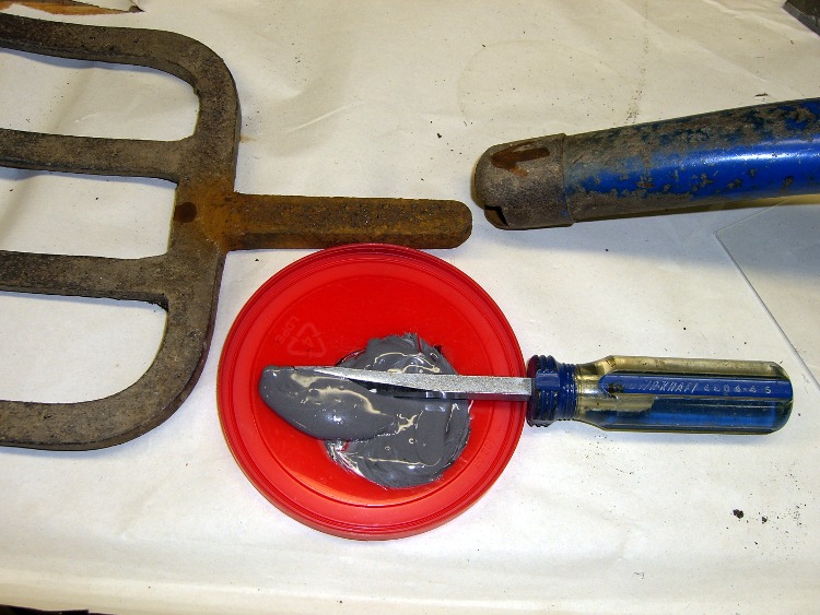
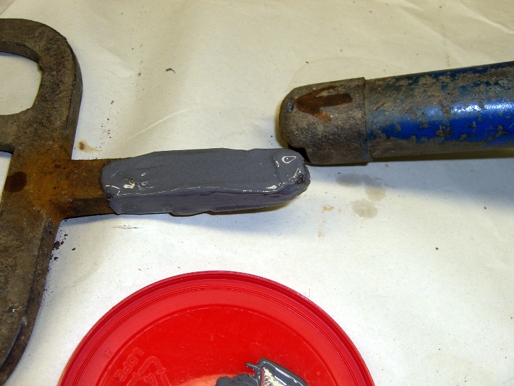
Mix the epoxy with my dedicated mixing screwdriver, butter up the shank, blob the excess epoxy into the socket, shove the parts together, clean off the outside globs, and let it cure overnight.
The trick is to get enough epoxy in the socket to fill the voids and mechanically lock the shank in place. This probably won’t work for forks used by burly guys who heave rocks over the horizon, but for our simple needs it’ll do just fine.
Pitchfork repair – epoxy mix
Pitchfork repair – buttering up the shank
Every now and again it’s OK to do an easy repair without a trace of CNC…
Maybe it’s just me, but all of the laser pointers I’ve bought, even the relatively spendy ones, have crappy switches and unstable battery contacts.
For example, this is the business end of a $12 (!) pen-style pointer. The battery contact was off-center and poorly secured; I pried the white plastic retainer out, bashed the spring into submission, and replaced the retainer with a length of heat-shrink tubing. It wasn’t pretty.
This pointer has an actual mechanical switch module inside, with a clicky mechanism actuated by the external button. Cheaper pointers seem to rely on bare PCB contacts bridged by the button’s base. Ugh.
Laser pointer battery orientation: positive DOWN
Memo to Self: The AAA cells fit into the housing with the positive terminal away from the laser head. The white plastic plug has a molded cross that could be mistaken for a + symbol, but it’s not.
I’m in the midst of cleaning up the shop after a winter of avoiding the too-cold basement. The best way I’ve found to pull this off is to pick up each object, do whatever’s needed to put it away, and move to the next object. Trying to be clever leads to paralysis, so I devote a few days to fixing up gadgets and putting tools back in their places. After a while, it gets to be rather soothing.
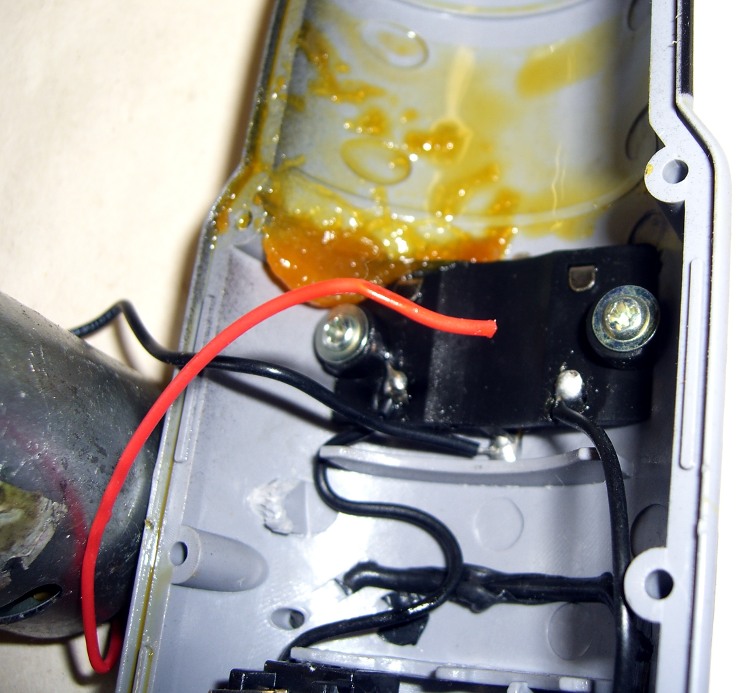
Broken wire in power screwdriver
Some months ago I snagged a power screwdriver from a discard pile; while it didn’t work, un-bending the battery pack connector solved that. It runs from a quartet of AA cells, which means I can use alkalines and it’ll always be ready to go. It’s not a high-torque unit, so I’m using it for case screws and similar easy tasks.
But it quickly became intermittent and finally would turn only clockwise. Onto the to-do heap it went…
Power screwdrivers consist of a battery, a motor with a planetary gear reduction transmission, and a cross-wired DPDT switch in between. Not much can go wrong and, if it turns at all, most likely the problem has something to do with the switch or wiring.
Opened it up, pulled out the motor, and, lo and behold, one of the wires has broken off the switch. As nearly as I can tell, pushing the switch that-a-way forced the solder tab down on the wire and made the connection, pushing it the other way pulled the tab off the wire.
While I had the hood up, I replaced the wires with slightly thicker and longer ones. Soldered everything back together, mushed the grease blobs back into the planetary gearing, and it works like a champ…
Now, fairly obviously, there’s absolutely no economic sense to this sort of thing, given that the driver probably cost under ten bucks, but I just can’t stand to see a perfectly good gadget wind up in the trash.
I’d love to do this sort of thing for a living, if only I could figure out how to avoid going broke while doing so. Maybe I can get me some of thatmy economic stimulus money that’s sloshing around these days?
With the epoxy cured overnight, I fired up the Sherline CNC mill to poke screw holes in the brass hinge splice.
The first step was to mill a flat-bottomed hole in the lower surface of the thin brass to expose the threaded hole in the remaining hinge plate. I crunched the end of the frame in a machinist’s clamp, then grabbed that in the Sherline milling machine vise; the frame is upside-down in the picture.
The brass stock was 0.015 inches, so I milled downward 0.020 inches to get through the epoxy. I’d love to say that worked perfectly, but I had to fiddle around a bit and eventually put a slight divot in the hinge plate.
That alignment was by pure eyeballometric guesstimation, but poking a small epoxy disk out of the threaded hole revealed that the 2 mm milled hole was centered on the hinge hole. Pretty close. Kinda-sorta. Good enough for my purposes, anyway.
Laser alignment to hinge hole
I aligned the spindle to the actual hinge hole with my laser aligner, a process that turned out to be surprisingly easy: note where the red dot vanishes on each side of the hole, split the difference, repeat for the Y axis, and you’re done.
Through-drilling top hole
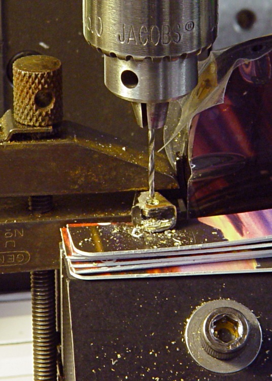
With the spindle centered, I ran a #60 drill through the threaded hole (which it just barely cleared) and poked a hole in the thicker top plate (which is on the bottom here, remember). The packing under the hinge is a cut-up credit card; a handy source of thin sheets of stiff plastic.
Then I flipped the frame over and drilled out the top hole with a #54 drill to clear the threads on a 00-90 machine screw. I’d like to say I did a precision alignment job, but what I actually did was chuck that little bitty drill up in my big drill press, run it on the slowest spindle speed (maybe 400 rpm), brace my arms on the table, and feed the frame onto the drill by hand. Works perfectly… if only because I’m enlarging the hole by, what, 7 thou on each side.
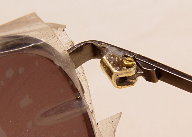
Finished hinge – top view
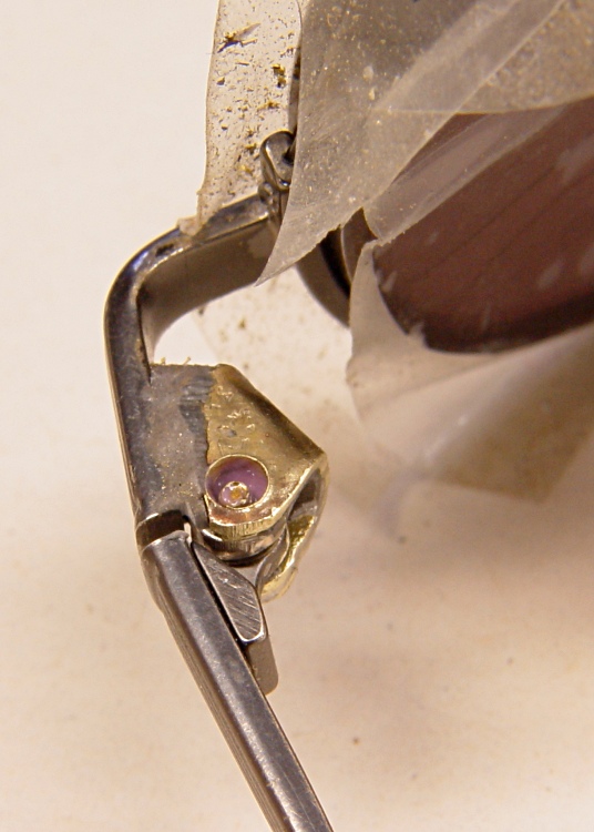
A bit of filing cleaned up the drill chaff inside the hinge so I could mount the earpiece on the frame and screw it in place. I don’t have a 00-90 tap and wouldn’t use it in a titanium frame anyway, so you can tell this isn’t going to have a happy outcome, but, by and large, the undoubtedly metric threads in the frame did a pretty good job of re-forming the 00-90 brass threads. Ugly, but serviceable.
Some Dremel-tool work with an itsy grinding wheel on the flexy shaft eroded the back side of the U-shaped brass and new hinge plate to clear the earpiece; I think it only took half a dozen trial fittings & tiny grindings before the earpiece folded properly.
A dab of low-strength purple Loctite in the threads and I’d say that screw is in there for life!
Finished hinge – side viewFinished hinge – bottom view
Then I cleaned it up with a miniature wire wheel and, hey, it’s got a certain geeky charm, doesn’t it?
I have my doubts about how well the epoxy affixes itself to the brass, so I suspect I’ll be drilling a hole or two to mechanically lock it in place with some urethane adhesive when it falls off.
If the remaining hinge plate fractures, however, then the frame is toast.
Until I get around to having the optical shop dye up another pair, these should suffice for my simple needs.
Trivia:
The plastic film on the lenses comes from a big roll of the stuff they use to protect CRT monitors in shipping. Works great for shop projects and, back in the day, I used it when I was hauling monitors around. I think it’d suck the front right off an LCD panel, so I haven’t used much of it lately.
If you’re following the pictures, you’ll notice that the dsc* numbering series resets right in the middle of the story. That’s where my Sony camera gagged while writing an image and explains why I don’t have pix of the first drilling steps.
The color balance is weird on the milling machine pix because the shop lights are much cooler than the warm compact fluorescent bulb hovering over the table.