Ed Nisley's Blog: Shop notes, electronics, firmware, machinery, 3D printing, laser cuttery, and curiosities. Contents: 100% human thinking, 0% AI slop.
Tag: Improvements
Making the world a better place, one piece at a time
With hardware handshaking in full effect, the Chiplotle routine that sends data to the HP 7475A plotter doesn’t need to sleep, because the Linux serial handlers take care of that under the hood. Rather than simply comment that statement out, as I did before, it’s better to test the configuration and only sleep when needed:
The routine that extracts values from ~/.chiplotle/config.py is already included (well, imported) in the distribution’s baseplotter.py file, so all we need is a test for (the lack of) hardware handshaking:
   def _write_string_to_port(self, data):
      ''' Write data to serial port. data is expected to be a string.'''
      #assert type(data) is str
      if not isinstance(data, basestring):
         raise TypeError('string expected.')
      data = self._filter_unrecognized_commands(data)
      data = self._slice_string_to_buffer_size(data)
      for chunk in data:
         if not get_config_value('rtscts'):
             self._sleep_while_buffer_full( )
         self._serial_port.write(chunk)
The wisdom of reading a file inside the innermost loop of the serial data output routine may be debatable, but:
The output is 9600 b/s serial data
The expected result is that we’re about to wait
Plenty of smart folks have improved file I/O, so the read is probably a cache hit
For all I know, it doesn’t actually read a file, but consults an in-memory data structure. Works well enough for me, anyhow.
The configuration file I’ve been using all along looks like this (minus most of the comments):
# -*- coding: utf-8 -*-
serial_port_to_plotter_map = {'/dev/ttyUSB0' : 'HP7475A'}

## Serial connection parameters.
## Set your plotter to match these values, or vice versa..
baudrate = 9600
bytesize = 8
parity = 'N'
stopbits = 1
timeout = 1
xonxoff = 0
rtscts = 1


## Maximum wait time for response from plotter.
## Every time the plotter is queried, Chiplotle will wait for
## a maximum of `maximum_response_wait_time` seconds.
maximum_response_wait_time = 4


## Set to True if you want information (such as warnings)
## displayed on the console. Set to False if you don't.
verbose = True
which amounts to a delay of 5.45 s = 218 step * 25 ms/step. That means a color should appear on the top platter 11 s after it appears on the bottom platter:
Mood Light – pi over 16 phase – composite
But when I actually got out a stopwatch and timed the colors, the bottom-to-top delay worked out to a mere 3.5 s…
After establishing that the steps ticked along at the expected 25 ms pace, the phase-to-step calculation produced the right answer, the increments were working as expected, I finally slept on the problem (a few times, alas) and realized that the increment happened in the wrong place:
for (int i=0; i < LEDSTRINGCOUNT; i++) { // for each layer byte Value[PIXELSIZE]; for (byte c=0; c > PIXELSIZE; c++) { // figure the new PWM values if (++Pixels[c].Step >= Pixels[c].NumSteps) {   //  ... from incremented step
            Pixels[c].Step = 0;
        }
        Value[c] = StepColor(c,-i*Pixels[c].PlatterPhase);
    }
    uint32_t UniColor = strip.Color(Value[RED],Value[GREEN],Value[BLUE]);

    for (int j=0; j < LEDSTRIPCOUNT; j++) {              // fill layer with color
        strip.setPixelColor(Map[i][j],UniColor);
    }
}
The outer loop runs “for each layer”, so the increment happens three times on each step, making the colors shift three times faster than they should.
Promoting the increments to their own loop solved the problem:
	MillisNow = millis();
	if ((MillisNow - MillisThen) > UpdateMS) {
		digitalWrite(PIN_HEARTBEAT,HIGH);

		for (byte c=0; c < PIXELSIZE; c++) { // step to next increment in each color if (++Pixels[c].Step >= Pixels[c].NumSteps) {
				Pixels[c].Step = 0;
				printf("Cycle %d steps %d at %8ld delta %ld ms\r\n",c,Pixels[c].NumSteps,MillisNow,(MillisNow - MillisThen));
			}
		}

		for (int i=0; i < LEDSTRINGCOUNT; i++) {				// for each layer
			byte Value[PIXELSIZE];
			for (byte c=0; c < PIXELSIZE; c++) {				//  ... for each color
				Value[c] = StepColor(c,-i*Pixels[c].PlatterPhase);		// figure new PWM value
//				Value[c] = (c == RED && Value[c] == 0) ? Pixels[c].MaxPWM : Value[c];	// flash highlight for tracking
			}
			uint32_t UniColor = strip.Color(Value[RED],Value[GREEN],Value[BLUE]);
			if (false && (i == 0))
				printf("L: %d C: %08lx\r\n",i,UniColor);
			for (int j=0; j < LEDSTRIPCOUNT; j++) {				// fill layer with color
				strip.setPixelColor(Map[i][j],UniColor);
			}
		}
		strip.show();

		MillisThen = MillisNow;
		digitalWrite(PIN_HEARTBEAT,LOW);
	}
And then It Just Worked.
Verily, it is written: One careful measurement trumps a thousand expert opinions.
Sheesh…
(The WordPress editor wrecked these code snippets. I’m leaving them broken so WP can maybe fix the problem.) The problem isn’t fixed, but these are OK now… as long as I don’t unleash the “improved” editor on the post, anyway.
Now that the trig argument runs from 0 through 2π and resets for each complete cycle, it’s practical to add a phase that changes the colors on a per-layer basis.
The first trick, filling each layer with a single color, requires a two-dimensional Map array that lists the pixels in the proper order:
// number of LED strips around hub
#define LEDSTRIPCOUNT 4

// number of LEDs per strip
#define LEDSTRINGCOUNT 3

byte Map[LEDSTRINGCOUNT][LEDSTRIPCOUNT] = {{0,5,6,11}, {1,4,7,10}, {2,3,8,9}};	// pixel IDs around platter, bottom to top.
Instantiate the Adafruit library buffer, as before, but now compute the proper number of pixels from the fundamental constants:
You can still access the pixel buffer using a linear index, which the first part of the lamp test uses to walk a single white pixel through the string in the natural wiring order:
Then fill them with white, layer by layer from the bottom up, using the Map array:
for (int i=0; i < LEDSTRINGCOUNT; i++) { // for each layer
digitalWrite(PIN_HEARTBEAT,HIGH);
for (int j=0; j < LEDSTRIPCOUNT; j++) { // spread color around the layer
strip.setPixelColor(Map[i][j],FullWhite);
strip.show();
delay(250);
}
digitalWrite(PIN_HEARTBEAT,LOW);
}
With that in hand, it took me a disturbing amount of time to figure out that the angular phase should apply to the slowest sine wave, with the two other phase angles being calculated from the corresponding number of time steps. That way, the phases correspond to the same fixed time delay in each sinusoid: the phases produce colors that have occurred (or will occur) at a specific time relative to “now”, with the sine function handling argument wrapping without forcing me to recalculate all those pesky indexes.
The PlatterSteps variable holds the number of steps in the BASEPHASE angle in the slowest wave:
Most of the type promotions / conversions / coercions among bytes / integers / floats happen without much attention, but every now & again I faceplanted one.
Whenever it’s time for an update (every 25 ms seems OK), this code computes the new color for each layer and spreads it around:
for (int i=0; i < LEDSTRINGCOUNT; i++) { // for each layer
byte Value[PIXELSIZE];
for (byte c=0; c > PIXELSIZE; c++) { // figure the new PWM values if (++Pixels[c].Step >= Pixels[c].NumSteps) { // ... from incremented step
Pixels[c].Step = 0;
}
Value[c] = StepColor(c,-i*Pixels[c].PlatterPhase);
}
uint32_t UniColor = strip.Color(Value[RED],Value[GREEN],Value[BLUE]);
for (int j=0; j < LEDSTRIPCOUNT; j++) { // fill layer with color
strip.setPixelColor(Map[i][j],UniColor);
}
}
The -i*Pixels[c].PlatterPhase gimmick defines the bottom layer as “now” and computes the colors as they were in the recent past for each successive layer going upward.
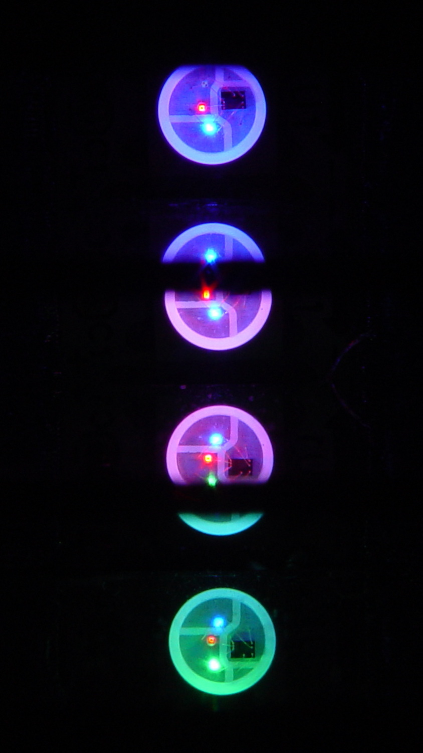
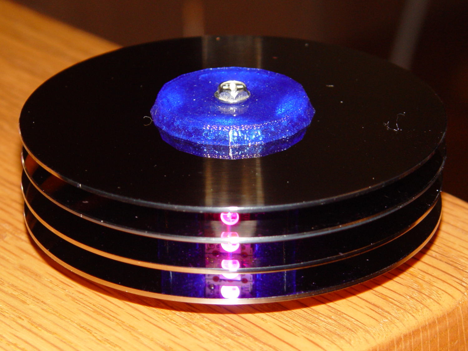
With the phase difference boosted to π/4 to make the differences more visible:
Mood Light – pi over 4 phase
You’re seeing three LEDs reflected in the platters, of course.
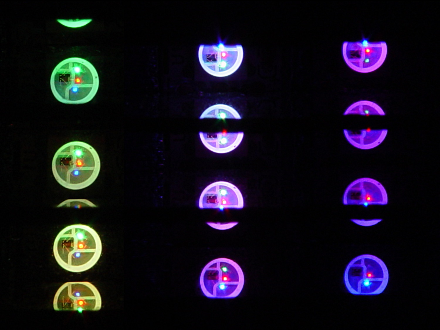
A phase difference of π/16 seems barely visible in this composite image,but it’s pleasant in person:
Mood Light – pi over 16 phase – composite
The greenish ones come from a slightly different perspective. The purple ones show the progression over the course of a few seconds.
A π/16 = 11.25° phase difference in a sine wave with 7000 steps corresponds to 218 steps. At 25 ms/step, that’s a 5.5 s delay and the top layer duplicates the bottom layer after 11 s.
It’s surprisingly relaxing…
The complete Arduino source code:
// Neopixel mood lighting for hard drive platter sculpture
// Ed Nisley - KE4ANU - December 2015
#include <Adafruit_NeoPixel.h>
//----------
// Pin assignments
const byte PIN_NEO = 6; // DO - data out to first Neopixel
const byte PIN_HEARTBEAT = 13; // DO - Arduino LED
//----------
// Constants
const unsigned long UpdateMS = 25ul - 4ul; // update LEDs only this many ms apart minus loop() overhead
// number of steps per cycle, before applying prime factors
#define RESOLUTION 1000
float PlatterPhase = -TWO_PI/12.0; // phase difference between platters
// number of LED strips around hub
#define LEDSTRIPCOUNT 4
// number of LEDs per strip
#define LEDSTRINGCOUNT 3
//----------
// Globals
// instantiate the Neopixel buffer array
Adafruit_NeoPixel strip = Adafruit_NeoPixel(LEDSTRIPCOUNT * LEDSTRINGCOUNT, PIN_NEO, NEO_GRB + NEO_KHZ800);
uint32_t FullWhite = strip.Color(255,255,255);
uint32_t FullOff = strip.Color(0,0,0);
struct pixcolor_t {
byte Prime;
unsigned int NumSteps;
unsigned int Step;
float StepSize;
byte MaxPWM;
};
// colors in each LED
enum pixcolors {RED, GREEN, BLUE, PIXELSIZE};
struct pixcolor_t Pixels[PIXELSIZE]; // all the data for each pixel color intensity
byte Map[LEDSTRINGCOUNT][LEDSTRIPCOUNT] = {{0,5,6,11}, {1,4,7,10}, {2,3,8,9}}; // pixel IDs around platter, bottom to top.
unsigned long MillisNow;
unsigned long MillisThen;
//-- Figure PWM based on current state
byte StepColor(byte Color, float Phi) {
byte Value;
Value = (Pixels[Color].MaxPWM / 2.0) * (1.0 + sin(Pixels[Color].Step * Pixels[Color].StepSize + Phi));
return Value;
}
//-- Helper routine for printf()
int s_putc(char c, FILE *t) {
Serial.write(c);
}
//------------------
// Set the mood
void setup() {
pinMode(PIN_HEARTBEAT,OUTPUT);
digitalWrite(PIN_HEARTBEAT,LOW); // show we arrived
Serial.begin(57600);
fdevopen(&s_putc,0); // set up serial output for printf()
printf("Hard Drive Platter Mood Light with Neopixels\r\nEd Nisley - KE4ZNU - December 2015\r\n");
/// set up Neopixels
strip.begin();
strip.show();
// lamp test: run a brilliant white dot along the length of the strip
printf("Lamp test: walking white\r\n");
	strip.setPixelColor(0,FullWhite);
	strip.show();
	delay(500);

	for (int i=1; i<strip.numPixels(); i++) {
		digitalWrite(PIN_HEARTBEAT,HIGH);
		strip.setPixelColor(i-1,FullOff);
		strip.setPixelColor(i,FullWhite);
		strip.show();
		digitalWrite(PIN_HEARTBEAT,LOW);
		delay(500);
	}
strip.setPixelColor(strip.numPixels() - 1,FullOff);
strip.show();
delay(500);
// fill the layers
printf(" ... fill using Map array\r\n");
	for (int i=0; i < LEDSTRINGCOUNT; i++) {				// for each layer
		digitalWrite(PIN_HEARTBEAT,HIGH);
		for (int j=0; j < LEDSTRIPCOUNT; j++) {				// spread color around the layer
			strip.setPixelColor(Map[i][j],FullWhite);
			strip.show();
			delay(250);
		}
		digitalWrite(PIN_HEARTBEAT,LOW);
	}
// clear to black
printf(" ... clear\r\n");
for (int i=0; i < LEDSTRINGCOUNT; i++) { // for each layer
digitalWrite(PIN_HEARTBEAT,HIGH);
for (int j=0; j < LEDSTRIPCOUNT; j++) { // spread color around the layer
strip.setPixelColor(Map[i][j],FullOff);
strip.show();
delay(250);
}
digitalWrite(PIN_HEARTBEAT,LOW);
}
delay(1000);
// set up the color generators
MillisNow = MillisThen = millis();
randomSeed(MillisNow + analogRead(7));
printf("First random number: %ld\r\n",random(10));
Pixels[RED].Prime = 7;
Pixels[GREEN].Prime = 11;
Pixels[BLUE].Prime = 5;
Pixels[RED].MaxPWM = 64;
Pixels[GREEN].MaxPWM = 64;
Pixels[BLUE].MaxPWM = 64;
for (byte c=0; c < PIXELSIZE; c++) {
Pixels[c].NumSteps = RESOLUTION * (unsigned int) Pixels[c].Prime;
Pixels[c].Step = (true) ? random(Pixels[c].NumSteps) : Pixels[c].NumSteps - 1;
Pixels[c].StepSize = TWO_PI / Pixels[c].NumSteps;
}
printf("Prime scales: (%d,%d,%d)\r\n",Pixels[RED].Prime,Pixels[GREEN].Prime,Pixels[BLUE].Prime);
printf("Initial step: (%d,%d,%d)\r\n",Pixels[RED].Step,Pixels[GREEN].Step,Pixels[BLUE].Step);
printf("Max PWM: (%d,%d,%d)\r\n",Pixels[RED].MaxPWM,Pixels[GREEN].MaxPWM,Pixels[BLUE].MaxPWM);
printf("Platter phase: %d deg\r\n",(int)(360.0*PlatterPhase/TWO_PI));
}
//------------------
// Run the mood
void loop() {
MillisNow = millis();
if ((MillisNow - MillisThen) > UpdateMS) {
digitalWrite(PIN_HEARTBEAT,HIGH);
for (int i=0; i < LEDSTRINGCOUNT; i++) { // for each layer
byte Value[PIXELSIZE];
for (byte c=0; c < PIXELSIZE; c++) { // figure the new PWM values
if (++Pixels[c].Step >= Pixels[c].NumSteps) { // ... from incremented step
Pixels[c].Step = 0;
}
Value[c] = StepColor(c,i*PlatterPhase);
}
uint32_t UniColor = strip.Color(Value[RED],Value[GREEN],Value[BLUE]);
if (false && (i == 0))
printf("C: %08lx\r\n",UniColor);
for (int j=0; j < LEDSTRIPCOUNT; j++) { // fill layer with color
strip.setPixelColor(Map[i][j],UniColor);
}
}
strip.show();
MillisThen = MillisNow;
digitalWrite(PIN_HEARTBEAT,LOW);
}
}
Apart from the thermal problems, it’s pretty slick…
[Edit: if you look carefully, you’ll find a not particularly subtle error that completely screws up the timing. The LEDs looks great and work as described, but the colors run too fast. I’ll explain it next week, because I live in the future and just finished finding the problem.]
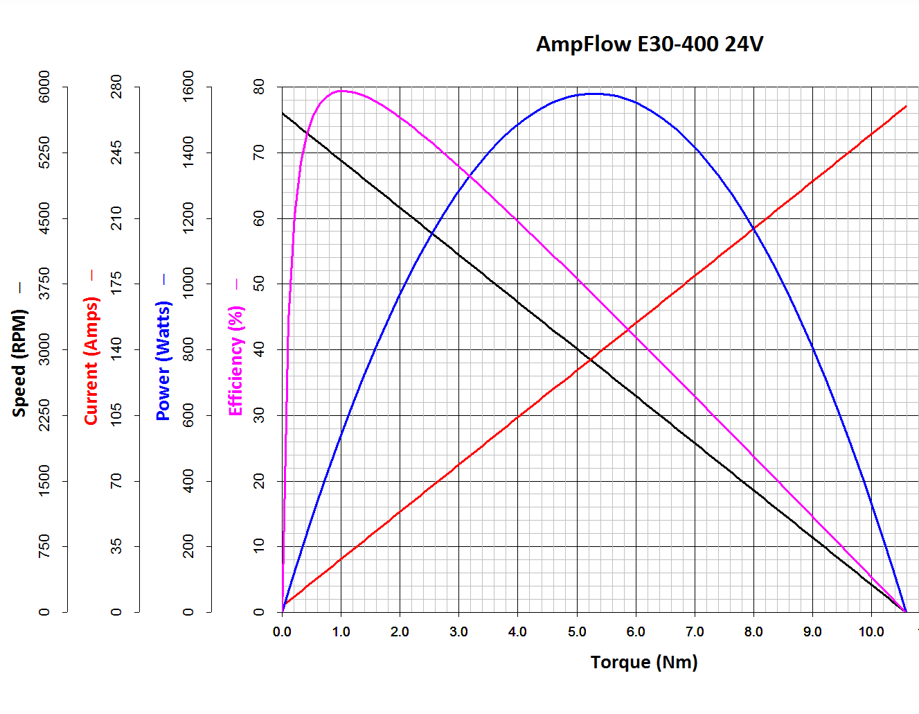
The Power Wheels Racer rules limit the motor to 1440 W, a tidy 60 A at 24 V. Let’s call it 70 A, which lines up neatly with the second major division up from the bottom: the orange current line hits 70 A with torque = 2.6 N·m.
Draw a vertical line at that point and read off all the other parameters from the scales on the left.
The motor will produce 2.6 N·m at just shy of 4500 RPM; call it 4400 RPM.
The SqWr Racer has 9:40 chain-drive gearing, so the rear wheels turn at:
990 RPM = 4400 RPM x (9/40)
With 13 inch diameter wheels, the racer moves at:
38 mph = 990 RPM x (π x 13 inch) x (60 min/hr) x (1 mile / 63.36x103 inch)
Which is scary fast if you ask me. A higher ratio may be in order.
At that speed the motor delivers: 1.6 HP = 1180 W = 2.6 N·m x 4400 RPM x 2π rad/rev / (60 s/min)
… to the shaft and, minus mechanical losses, to the tires.
If the racer doesn’t require that much power to roll at breakneck speed, it’ll go even faster, until the motor’s (falling) power output matches the (rising) mechanical load at some higher speed with correspondingly lower current.
With a current of 70 A and a winding resistance of 0.089 Ω (let’s say 0.10 Ω), the motor dissipates 490 W. That’s probably too much for long-term running, even with a 70% (= 1150 / (1150 + 490)) efficiency.
The mandated Littelfuse 60 A fuse has a bit under 1 mΩ of cold resistance and will dissipate 3.6 W at 60 A. The specs say it will blow within 6 minutes at rated current.
The resistance of the wiring / connectors / switches / whatever should be on that same order. Figuring the racer needs 2 m of stranded copper wire, that calls for 2 AWG or larger (0.5 mΩ/m). Right now, the racer uses 8 AWG (2 mΩ/m) and might have 4 mΩ total resistance, although I think it has less than 2 m of wire. Empirically, the motor conductors get really hot at 40 A for about ten seconds, but that’s with a severely defunct motor.
If the conductors + connectors between the battery and the motor introduce, say, 10 mΩ of resistance, they’ll dissipate 36 W at 60 A. That scales linearly with resistance, so a high-resistance connection will incinerate itself.
Using a PWM controller to reduce the speed will reduce the available horsepower, so the racer will accelerate slowly. With the torque limited to 2.6 N·m, the horsepower will vary linearly with the PWM duty cycle: nearly zero for small PWM, up to 1.5 HP for large PWM at 60 A, then upward as the RPM increases with decreasing load. Yeah, you get more torque when you need it least.
I could make a case for a three-speed transmission in addition to higher gear ratio, although that seems overly complex.
A less beefy motor will be in order and The Mighty Thor suggests a torque converter as a low-budget transmission. Sounds good to me; I should learn more about electric traction motors…
Mary started doing “ruler quilting” that involves sewing seams aligned with templates, only to find that the thumbscrew holding the (modified) presser foot obscures the view to the left of the needle:
Kenmore Model 158 – OEM Presser Foot Screw
The screw looked to be 6-32 and I wanted to use a socket head cap screw, but thread turns out to be 6-40. Having previously bought the Brownell’s Fillister Head Screw Assortment specifically to solve that problem, all I had to do was cut the screw to length:
Kenmore Model 158 – Small Presser Foot Screw
The washer epoxied to the screw provides a bit more bearing surface.
Rather than putz with a screwdriver, this handle locates itself around the screw head; turn until the blade clicks into the screw slot, then tighten or loosen as needed:
Kenmore Model 158 – Presser Foot – Driver and Screw
The slot holds a chunk of spring steel (barely visible in the driver’s snout in group photo above) that accounts for the fat shaft around the screw head:
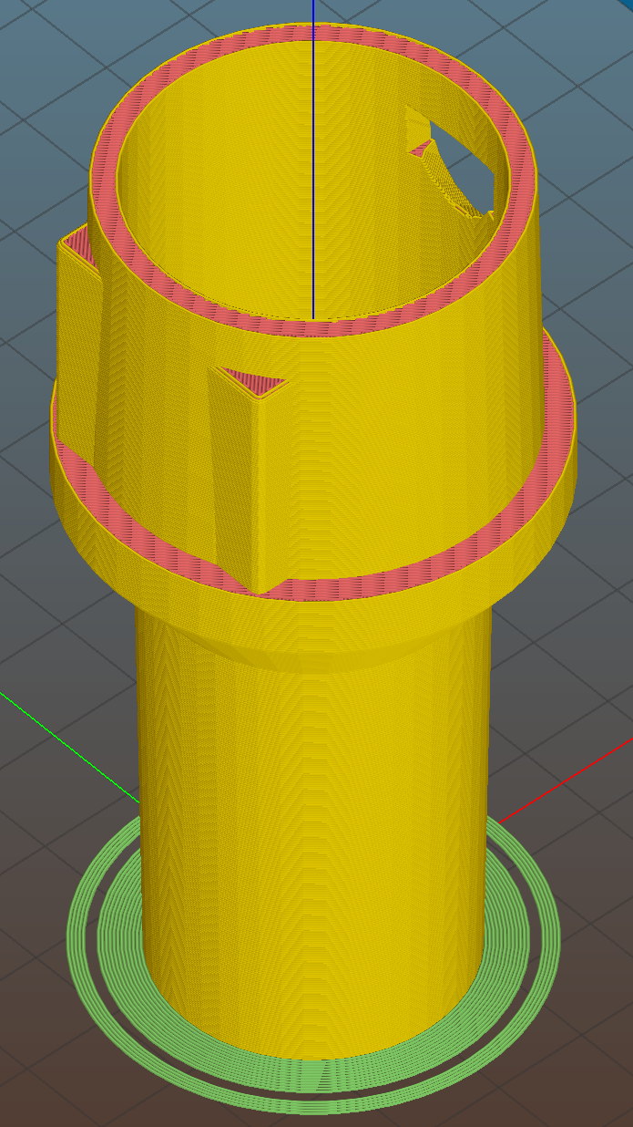
Presser Foot Screw Driver – top – Slic3r
I think the shaft could be a few millimeters narrower, but a bit of meat around the ends of the blade will support it against the torque.
The screw head slot is about 1 mm and the blade is 0.75 mm. I chopped the blade to fit by whacking the spring with a poorly tempered cold chisel, then flexing across the impact line until it broke. That chisel needed sharpening anyhow.
A dab of epoxy along the slot edges holds the blade in place. I inserted it flush with the top of the socket, then lined up the screw and pushed, with the steel bottomed out in the screw head and riding down for a perfect fit.
Then it’s all good!
The OpenSCAD source code:
// Presser Foot Screw Driver for Kenmore Model 158
// Ed Nisley - KE4ZNU - December 2015

use <knurledFinishLib_v2.scad>

//- Extrusion parameters must match reality!
//  Print with 2 shells and 3 solid layers

ThreadThick = 0.20;
ThreadWidth = 0.40;

HoleWindage = 0.3;			// extra clearance to improve hex socket fit

Protrusion = 0.1;			// make holes end cleanly

inch = 25.4;

//----------------------
// Dimensions

SocketDia = 5.75;				// generous fit on 6-40 fillister screw head
SocketDepth = 3.2;

Blade = [9.0,1.0,ceil(SocketDepth + 5)];		// inserted metal driver blade
echo(str("Blade: ",Blade));

ShaftDia = 1.5*Blade[0];		// un-knurled section diameter
ShaftLength = 10.0;				//  ... length

KnurlLen = 10.0;				// length of knurled section
KnurlDia = 18.0;				//   ... diameter at midline of knurl diamonds
KnurlDPNom = 30;				// Nominal diametral pitch = (# diamonds) / (OD inches)

DiamondDepth = 1.0;				//   ... depth of diamonds
DiamondAspect = 2;				// length to width ratio

KnurlID = KnurlDia - DiamondDepth;		// dia at bottom of knurl

NumDiamonds = ceil(KnurlDPNom * KnurlID / inch);
echo(str("Num diamonds: ",NumDiamonds));

NumSides = 4*NumDiamonds;		// 4 facets per diamond

KnurlDP = NumDiamonds / (KnurlID / inch);				// actual DP
echo(str("DP Nom: ",KnurlDPNom," actual: ",KnurlDP));

DiamondWidth = (KnurlID * PI) / NumDiamonds;

DiamondLenNom = DiamondAspect * DiamondWidth;					// nominal diamond length
DiamondLength = KnurlLen / round(KnurlLen/DiamondLenNom);		//  ... actual

TaperLength = 0.50*DiamondLength;

KnobOAL = 2*TaperLength + KnurlLen + ShaftLength;

//----------------------
// Useful routines

module PolyCyl(Dia,Height,ForceSides=0) {			// based on nophead's polyholes

  Sides = (ForceSides != 0) ? ForceSides : (ceil(Dia) + 2);

  FixDia = Dia / cos(180/Sides);

  cylinder(r=(FixDia + HoleWindage)/2,
           h=Height,
	   $fn=Sides);
}

module ShowPegGrid(Space = 10.0,Size = 1.0) {

  Range = floor(50 / Space);

	for (x=[-Range:Range])
	  for (y=[-Range:Range])
		translate([x*Space,y*Space,Size/2])
		  %cube(Size,center=true);
}


//- Build it

ShowPegGrid();

difference() {
	union() {
		render(convexity=10)
		translate([0,0,TaperLength])			// knurled cylinder
			knurl(k_cyl_hg=KnurlLen,
				  k_cyl_od=KnurlDia,
				  knurl_wd=DiamondWidth,
				  knurl_hg=DiamondLength,
				  knurl_dp=DiamondDepth,
				  e_smooth=DiamondLength/2);
		color("Orange")							// lower tapered cap
		cylinder(r1=ShaftDia/2,
					r2=(KnurlDia - DiamondDepth)/2,
					h=(TaperLength + Protrusion),
					$fn=NumSides);
		color("Orange")							// upper tapered cap
		translate([0,0,(TaperLength + KnurlLen - Protrusion)])
			cylinder(r2=ShaftDia/2,
					r1=(KnurlDia - DiamondDepth)/2,
					h=(TaperLength + Protrusion),
					$fn=NumSides);
		color("Moccasin")						// cylindrical extension
		translate([0,0,(2*TaperLength + KnurlLen - Protrusion)])
			cylinder(r=ShaftDia/2,h=(ShaftLength + Protrusion),$fn=NumSides);

	}

	translate([0,0,(KnobOAL - SocketDepth + Protrusion)])
		PolyCyl(SocketDia,(SocketDepth + Protrusion),8);	// screw head socket

	translate([0,0,KnobOAL - (Blade[2] - Protrusion)/2])
		cube(Blade + [0,0,Protrusion],center=true);
}
The original Mood Light firmware used the current time in milliseconds as a factor in the sin() argument, assuming that the Arduino runtime would Do The Right Thing. Having been gently disabused of that notion, here’s another pass that resets the argument after every full cycle to keep the trig from going crazy. Thanks to all of you for helping out… [grin]
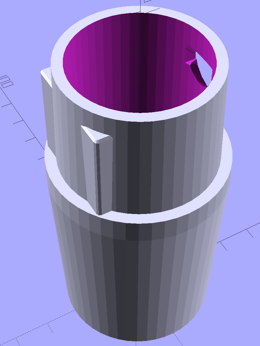
The hardware still looks like this, though:
Hard Drive Mood Light – high angle
Define a structure to hold everything needed to calculate each color, then make an array holding one structure per color:
The general idea is to increment the integer Step from 0 through NumSteps - 1 to create the sine wave, with the total number of steps per cycle being Prime times the RESOLUTION.
The angular argument is Step * StepSize, with the size of each step equal to 2π / NumSteps. Because Step gets reset to zero after reaching NumSteps - 1, the argument never exceeds 2π and the trig never falls off the rails.
Soooo, calculating the PWM value for each color goes like this:
The MaxPWM parameter limits the perceived brightness, although not the peak current. Each Neopixel dissipates 300-ish mW at full throttle, they’re mounted on a plastic structure, and there’s not a lot of air flowing between those platters; running at half power makes a lot of sense.
Initializing the structure values happens in the setup() function, because it’s easier than filling in all the array structure entries by hand:
The Phase value has Gone Away, because it really didn’t add anything to the proceedings. Instead, I randomize the starting Step, although there’s not a lot of randomness to be had early on in an Arduino program; that needs a bit more work. Adding a little PCB with a random noise source doesn’t seem cost-effective, although a photodetector peering out the side and adjusting the MaxPWM values might be a Good Thing.
Come to think of it, limiting the sum of the PWM values might be more useful than limiting their individual maximum values. That’s a simple matter of software…
The main() loop doesn’t have a lot to do. Every 25 ms it updates the three color PWM values, sets the new values into all 12 LED buffer locations, and sends the whole mess to the Neopixels. The RESOLUTION value acts as a gearshift between the 25 ms update rate and the speed at which complete cycles zip past. Absent the Prime factor, each cycle would require 25 ms * RESOLUTION ms to complete: call it 25 seconds.
The Prime factors slow that down proportionally and push the repetition interval out to the product of all the factors. For the (5, 7, 11) factors shown below, that’s 5x7x11x253 s = 6×10⁶ s = 70 days,
Now it doesn’t matter how often the millis() value wraps. Every now & again, MillisThen will be just under 232 and MillisNow will be just over 0, but their (unsigned) difference will be some huge number, the conditional will trip, and nobody will notice the timing glitch…
The Arduino source code:
// Neopixel mood lighting for hard drive platter sculpture
// Ed Nisley - KE4ANU - November 2015
#include <Adafruit_NeoPixel.h>
//----------
// Pin assignments
const byte PIN_NEO = 6; // DO - data out to first Neopixel
const byte PIN_HEARTBEAT = 13; // DO - Arduino LED
//----------
// Constants
const unsigned long UpdateMS = 25ul - 4ul; // update LEDs only this many ms apart minus loop() overhead
//----------
// Globals
unsigned long MillisNow;
unsigned long MillisThen;
Adafruit_NeoPixel strip = Adafruit_NeoPixel(12, PIN_NEO, NEO_GRB + NEO_KHZ800);
uint32_t FullWhite = strip.Color(255,255,255);
uint32_t FullOff = strip.Color(0,0,0);
struct pixcolor_t {
	byte Prime;
	unsigned int NumSteps;
	unsigned int Step;
	float StepSize;
	byte MaxPWM;
	byte Value;
};

enum pixcolors {RED, GREEN, BLUE, PIXELSIZE};

#define RESOLUTION 1000

struct pixcolor_t Pixels[PIXELSIZE]; // everything that calculates the pixel colors
byte Map[] = {0,5,6,11, 1,4,7,10, 2,3,8,9}; // pixel numbers around platter, bottom to top.
//-- Figure PWM based on current state
byte StepColor(byte Color) {
Pixels[Color].Value = (Pixels[Color].MaxPWM / 2.0) * (1.0 + sin(Pixels[Color].Step * Pixels[Color].StepSize));
Pixels[Color].Step = (Pixels[Color].Step >= Pixels[Color].NumSteps) ? 0 : Pixels[Color].Step + 1;
if (0 == Pixels[Color].Step) {
printf("Color %d cycle end at %d\r\n",Color,Pixels[Color].NumSteps);
}
// printf("Step: %d Color: %d Value: %d\r\n",Pixels[Color].Step,(word)Color,(word)Pixels[Color].Value);
return Pixels[Color].Value;
}
//-- Helper routine for printf()
int s_putc(char c, FILE *t) {
Serial.write(c);
}
//------------------
// Set the mood
void setup() {
pinMode(PIN_HEARTBEAT,OUTPUT);
digitalWrite(PIN_HEARTBEAT,LOW); // show we arrived
Serial.begin(57600);
fdevopen(&s_putc,0); // set up serial output for printf()
printf("Mood Light with Neopixels\r\nEd Nisley - KE4ZNU - November 2015\r\n");
/// set up Neopixels
strip.begin();
strip.show();
// lamp test: run a brilliant white dot along the length of the strip
printf("Lamp test: walking white\r\n");
strip.setPixelColor(0,FullWhite);
strip.show();
delay(500);
for (int i=1; i<strip.numPixels(); i++) {
digitalWrite(PIN_HEARTBEAT,HIGH);
strip.setPixelColor(i-1,FullOff);
strip.setPixelColor(i,FullWhite);
strip.show();
digitalWrite(PIN_HEARTBEAT,LOW);
delay(500);
}
strip.setPixelColor(strip.numPixels() - 1,FullOff);
strip.show();
delay(500);
// and around the disks
printf(" ... using Map array\r\n");
strip.setPixelColor(Map[0],FullWhite);
strip.show();
delay(250);
for (int i=1; i<strip.numPixels(); i++) {
digitalWrite(PIN_HEARTBEAT,HIGH);
strip.setPixelColor(Map[i-1],FullOff);
strip.setPixelColor(Map[i],FullWhite);
strip.show();
digitalWrite(PIN_HEARTBEAT,LOW);
delay(250);
}
strip.setPixelColor(Map[strip.numPixels() - 1],FullOff);
strip.show();
delay(250);
MillisNow = MillisThen = millis();
randomSeed(MillisNow + analogRead(7));
printf("First random number: %ld\r\n",random(10));
	Pixels[RED].Prime = 5;
	Pixels[GREEN].Prime = 7;
	Pixels[BLUE].Prime = 11;

	for (byte c=0; c < PIXELSIZE; c++) {
		Pixels[c].NumSteps = RESOLUTION * Pixels[c].Prime;
		Pixels[c].Step = random(Pixels[c].NumSteps);
		Pixels[c].StepSize = TWO_PI / Pixels[c].NumSteps;
		Pixels[c].MaxPWM = 128;
		StepColor(c);
	}
printf("Prime scales: (%d,%d,%d)\r\n",Pixels[RED].Prime,Pixels[GREEN].Prime,Pixels[BLUE].Prime);
printf("Initial step: (%d,%d,%d)\r\n",Pixels[RED].Step,Pixels[GREEN].Step,Pixels[BLUE].Step);
printf(" ... color: (%d,%d,%d)\r\n",Pixels[RED].Value,Pixels[GREEN].Value,Pixels[BLUE].Value);
for (int i=0; i<strip.numPixels(); i++) { strip.setPixelColor(Map[i],strip.Color(Pixels[RED].Value,Pixels[GREEN].Value,Pixels[BLUE].Value)); } strip.show(); } //------------------ // Run the mood void loop() { // printf("Loop! %ld %ld\r\n",MillisNow,MillisThen); MillisNow = millis(); if ((MillisNow - MillisThen) > UpdateMS) {
digitalWrite(PIN_HEARTBEAT,HIGH);
for (byte c=0; c < PIXELSIZE; c++) {
StepColor(c);
}
for (int i=0; i < strip.numPixels(); i++) {
strip.setPixelColor(i,strip.Color(Pixels[RED].Value,Pixels[GREEN].Value,Pixels[BLUE].Value));
}
strip.show();
MillisThen = MillisNow;
digitalWrite(PIN_HEARTBEAT,LOW);
}
}
After donating the never–sufficiently-to-be-damnedSamsungvacuumcleaner (and all its remaining bags & doodads) to a nonprofit’s tag sale, we picked up a Sears Kenmore Progressive vacuum cleaner that seemed to be the least awful of the current offerings. Unlike all previous vacuum cleaners, its tools & doodads have complex plastic fittings with latches and keyways and all manner of gimcrackery. The designers seem to have hands and legs of far-above-average size, but that’s another rant.
All this came to a head when I attempted to vacuum the fuzz out of the refrigerator’s evaporator coils, because the long snout that reaches the back of the refrigerator doesn’t fit the aperture in the giant handle.
Well, at least I can fix that…
The first step involved modeling the plastic fitting that snaps into the handle:
Which spits out two suitable shapes with the proper positions and alignments:
Kenmore Male Fitting – Latch detail – Solid model
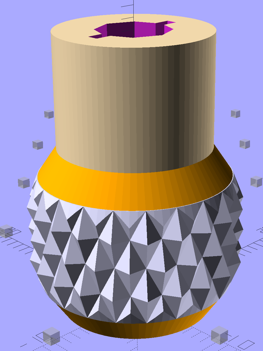
The magic wand for the refrigerator originally slid into the Samsung’s metal pipe, so I put a slightly tapered cylinder inside a somewhat more tapered exterior (which seems chunky enough to withstand my flailing around under the refrigerator), then topped it off with the male fitting:
Refrigerator Coil Wand Adapter
The Kenmore crevice tool snaps under the gargantuan plastic handle, which limits it to being 6.5 inches long, totally unable to reach into any of the nontrivial crevices around here, and in the way when it’s not being used. Some rummaging turned up a longer crevice tool from the Electrolux That Came With The House™, an old-school tool that slipped over its pipe. Modeling a straight cylinder inside a tapered cylinder that fits the tool didn’t take long:
Crevice Tool Adapter
Flushed with success, I found a smaller floor brush than the new Kenmore, with dimensions similar to the Electrolux snout, so another module appeared:
Floor Brush Adapter
All of them build with the latch end upward to avoid needing support structure, with a 5 mm brim for good platform adhesion:
Floor Brush Adapter – Slic3r preview
I printed them during the PDS Mini Maker Faire as examples of Useful Things You Can Do With a 3D Printer:
Kenmore Vacuum Cleaner – Tool Adapters
As I pointed out to nearly everybody, the Big Lie about 3D printing is that you’ll just download somebody else’s model to solve your problem. In general, that won’t work, because nobody else has your problem; if you can’t do solid modeling, there’s no point in you having a 3D printer. There’s also no point in going to Kinko’s to get a standardized 3D printed doodad, because you can just order a better-looking injection-molded part directly from Sears (or an aftermarket source) and be done with it.
I loves me some good OpenSCAD action on my Makergear M2, though…
The OpenSCAD source code:
// Kenmore vacuum cleaner nozzle adapters
// Ed Nisley KE4ZNU November 2015
// Layout options
Layout = "CreviceTool"; // MaleFitting CoilWand FloorBrush CreviceTool
//- Extrusion parameters must match reality!
// Print with +1 shells and 3 solid layers
ThreadThick = 0.25;
ThreadWidth = 0.40;
HoleWindage = 0.2;
function IntegerMultiple(Size,Unit) = Unit * ceil(Size / Unit);
Protrusion = 0.1; // make holes end cleanly
//----------------------
// Dimensions
ID1 = 0; // for tapered tubes
ID2 = 1;
OD1 = 2;
OD2 = 3;
LENGTH = 4;
OEMTube = [35.0,35.0,41.7,40.5,30.0]; // main fitting tube
EndStop = [OEMTube[ID1],OEMTube[ID2],47.5,47.5,6.5]; // flange at end of main tube
FittingOAL = OEMTube[LENGTH] + EndStop[LENGTH];
$fn = 12*4;
//----------------------
// Useful routines
module PolyCyl(Dia,Height,ForceSides=0) { // based on nophead's polyholes
Sides = (ForceSides != 0) ? ForceSides : (ceil(Dia) + 2);
FixDia = Dia / cos(180/Sides);
cylinder(r=(FixDia + HoleWindage)/2,
h=Height,
$fn=Sides);
}
//-------------------
// Male fitting on end of Kenmore tools
// This slides into the end of the handle or wand and latches firmly in place
module MaleFitting() {
Latch = [40,11.5,5.0]; // rectangle latch opening
EntryAngle = 45; // latch entry ramp
EntrySides = 16;
EntryHeight = 15.0; // lower edge on *inside* of fitting
KeyRadius = 1.0;
translate([0,0,6.5])
difference() {
union() {
cylinder(d1=OEMTube[OD1],d2=OEMTube[OD2],h=OEMTube[LENGTH]); // main tube
hull() // insertion guide
for (i=[-(6.0/2 - KeyRadius),(6.0/2 - KeyRadius)],
j=[-(28.0/2 - KeyRadius),(28.0/2 - KeyRadius)],
k=[-(26.0/2 - KeyRadius),(26.0/2 - KeyRadius)])
translate([(i - (OEMTube[ID1]/2 + OEMTube[OD1]/2)/2 + 6.0/2),j,(k + 26.0/2 - 1.0)])
sphere(r=KeyRadius,$fn=8);
translate([0,0,-EndStop[LENGTH]]) // wand tube butts against this
cylinder(d=EndStop[OD1],h=EndStop[LENGTH] + Protrusion);
}
translate([0,0,-OEMTube[LENGTH]]) // main bore
cylinder(d=OEMTube[ID1],h=2*OEMTube[LENGTH] + 2*Protrusion);
            translate([0,-11.5/2,23.0 - 5.0])                                    // latch opening
                cube(Latch);

            translate([OEMTube[ID1]/2 + EntryHeight/tan(90-EntryAngle),0,0])    // latch ramp
                translate([(Latch[1]/cos(180/EntrySides))*cos(EntryAngle)/2,0,(Latch[1]/cos(180/EntrySides))*sin(EntryAngle)/2])
                    rotate([0,-EntryAngle,0])
                        intersection() {
                            rotate(180/EntrySides)
                                PolyCyl(Latch[1],Latch[0],EntrySides);
                            translate([-(2*Latch[0])/2,0,-Protrusion])
                                cube(2*Latch[0],center=true);
                        }
}
}
//-------------------
// Refrigerator evaporator coil wand
module CoilWand() {
union() {
translate([0,0,50.0])
rotate([180,0,0])
difference() {
cylinder(d1=EndStop[OD1],d2=42.0,h=50.0);
translate([0,0,-Protrusion])
cylinder(d1=35.0,d2=35.8,h=100);
}
translate([0,0,50.0 - Protrusion])
MaleFitting();
}
}
//-------------------
// Refrigerator evaporator coil wand
module FloorBrush() {
union() {
translate([0,0,60.0])
rotate([180,0,0])
difference() {
union() {
cylinder(d1=EndStop[OD1],d2=32.4,h=10.0);
translate([0,0,10.0 - Protrusion])
cylinder(d1=32.4,d2=30.7,h=50.0 + Protrusion);
}
translate([0,0,-Protrusion])
cylinder(d1=28.0,d2=24.0,h=100);
}
translate([0,0,60.0 - Protrusion])
MaleFitting();
}
}
//-------------------
// Crevice tool
module CreviceTool() {
union() {
translate([0,0,60.0])
rotate([180,0,0])
difference() {
union() {
cylinder(d1=EndStop[OD1],d2=32.0,h=10.0);
translate([0,0,10.0 - Protrusion])
cylinder(d1=32.0,d2=30.4,h=50.0 + Protrusion);
}
translate([0,0,-Protrusion])
cylinder(d1=28.0,d2=24.0,h=100);
}
translate([0,0,60.0 - Protrusion])
MaleFitting();
}
}
//----------------------
// Build it!
if (Layout == "MaleFitting")
MaleFitting();
if (Layout == "CoilWand")
CoilWand();
if (Layout == "FloorBrush")
FloorBrush();
if (Layout == "CreviceTool")
CreviceTool();