Finally, the as-built hardware for the Avalanche Noise Random Number Display gadget:

The noise interconnection consists of one little wire:

The noise generator, amplifier, and bias power supply:

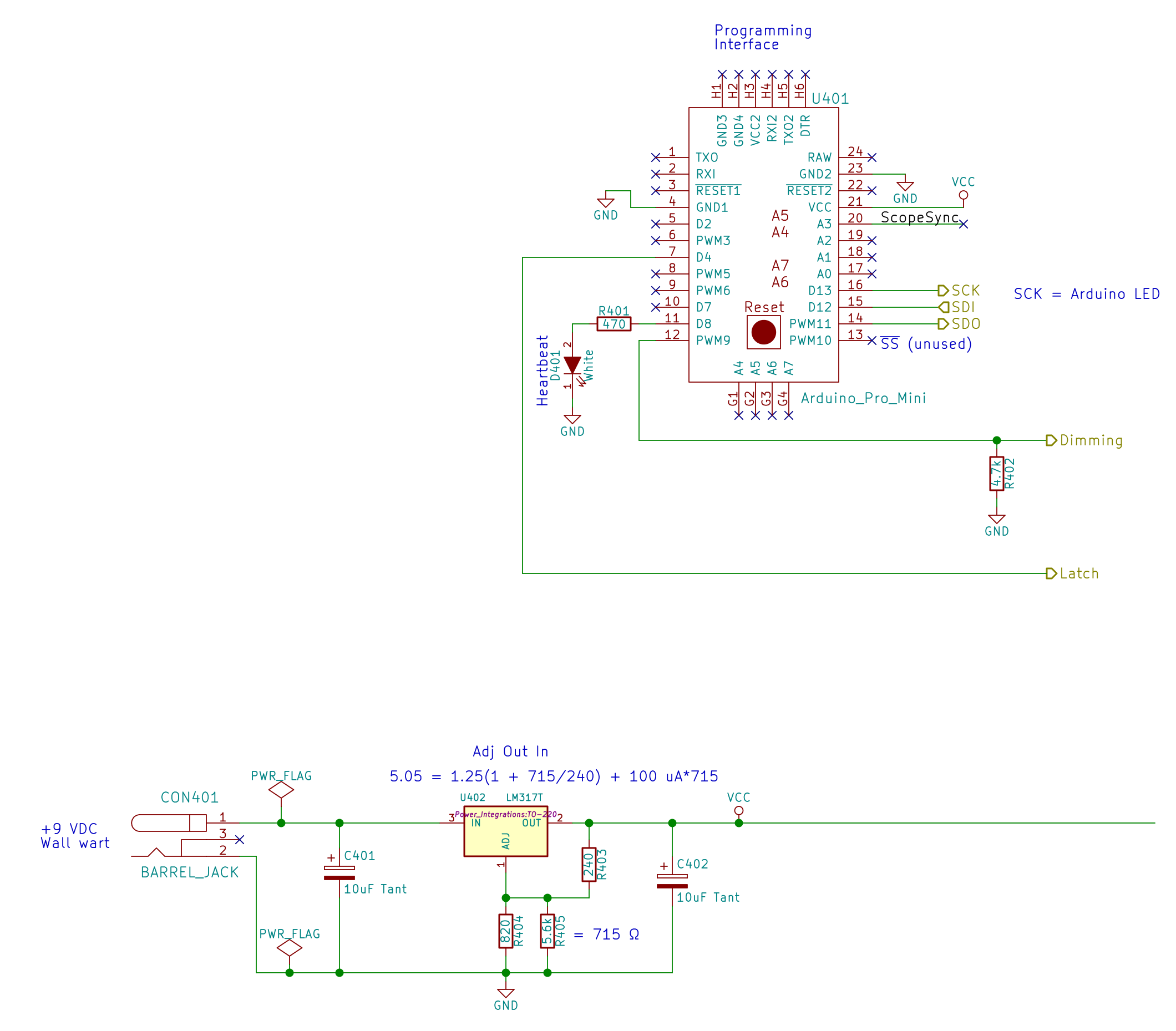
The Arduino (Pro Mini, at least) and the logic / LED power supply:
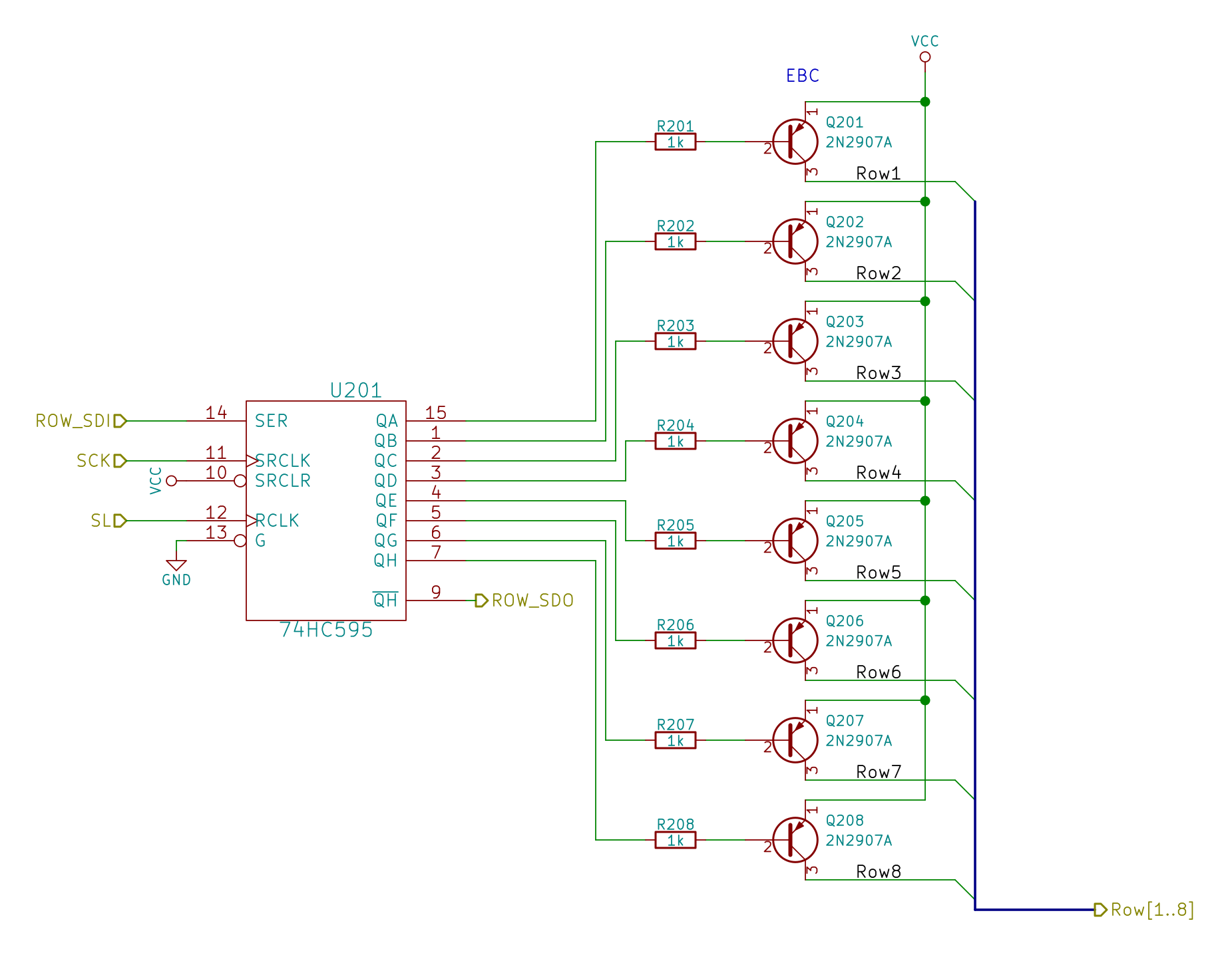
The row drivers:
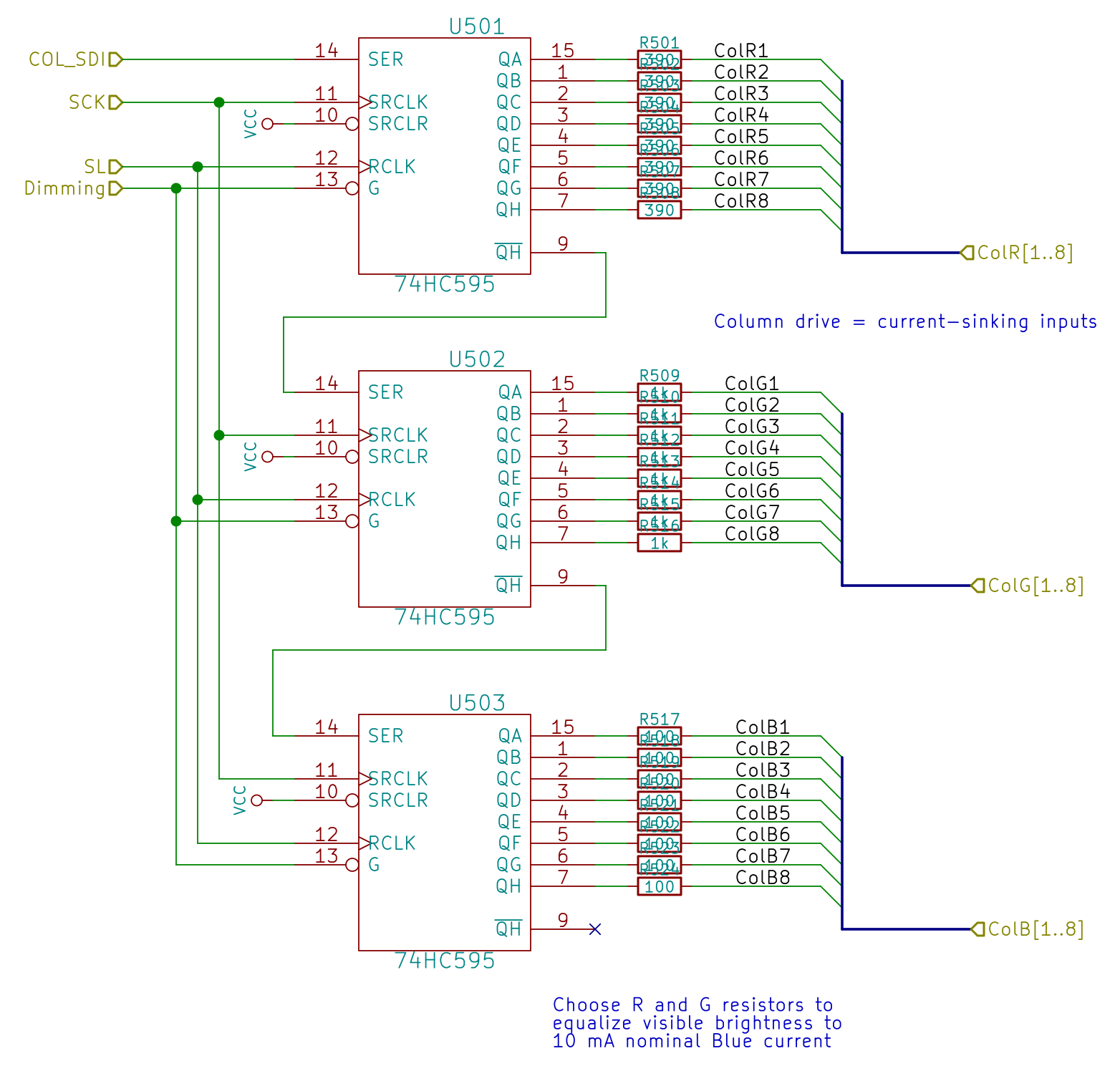
And the red-green-blue LED column drivers:
All of which make the common-anode RGB LED matrix blink merrily away:

Now all it needs is a dollop of source code…

Comments
6 responses to “Avalanche Noise Amp: Hardware”
The extra curled wire tacked to the top of Arduino caught my eye. At first I thought it was the “single wire”, but it didn’t seem to go anywhere. Then I looked at the rest of the schematics and saw a pin marked “scope sync”. Aha! I do the same thing myself, tack a curled bit of wire to a pin I want to monitor, so I can clip a scope probe onto it. Great minds, and all that.
It didn’t actually start curled; that board has been doing a lot of traveling under, mmmm, inhospitable conditions. I’m amazed none of the tack-soldered SMD resistors or connections have fallen off yet.
Just out of sight behind the Arduino is the U-shaped stiff wire lead I always solder to circuit ground for the scope clips. Betcha you do that, too. [grin]
(No good at RF, fine for digital & simple analog stuff.)
[…] « Avalanche Noise Amp: Hardware […]
[…] to be had early on in an Arduino program; that needs a bit more work. Adding a little PCB with a random noise source doesn’t seem cost-effective, although a photodetector peering out the side and adjusting the […]
[…] a picture of my circuitry, anyhow, there in the upper-right […]
[…] a sucker for noise sources, I spent some time pondering the […]