In the quest for More Light around the Kenmore 158’s needle, I’m replacing the pair of 10 mm LEDs with a pair of 21 V / 115 mA = 2.5 W surface-mount emitters that require a good heatsink. Because the heatsink must mount inside the sewing machine’s end cap, there’s not much air circulation: when sizing the heatsink, I figure that nothing exceeds like excess.
There doesn’t seem to be any way to measure the available space inside the hinged end cap, so the plan is to fit the largest possible heatsink, run it for a while, and then build a smaller (and presumably less awkward) heatsink based on those measurements.
I sawed a slice off an aluminum heatsink harvested from a junked PC, wrapped masking tape around it, and filled it with machinable wax to prevent the fins from chattering:

Pouring the wax into a cold heatsink worked about as poorly as you’d expect, so I held the heatsink over the stove burner, slowly remelted the wax into the bottom of the fins, and topped it off with more wax from the pot. I’m almost certainly using too little fire; the stuff melts at a bit under 300 °F and doesn’t really get liquid at any temperature I was comfortable with. The double boiler we use for candle wax won’t get nearly hot enough.
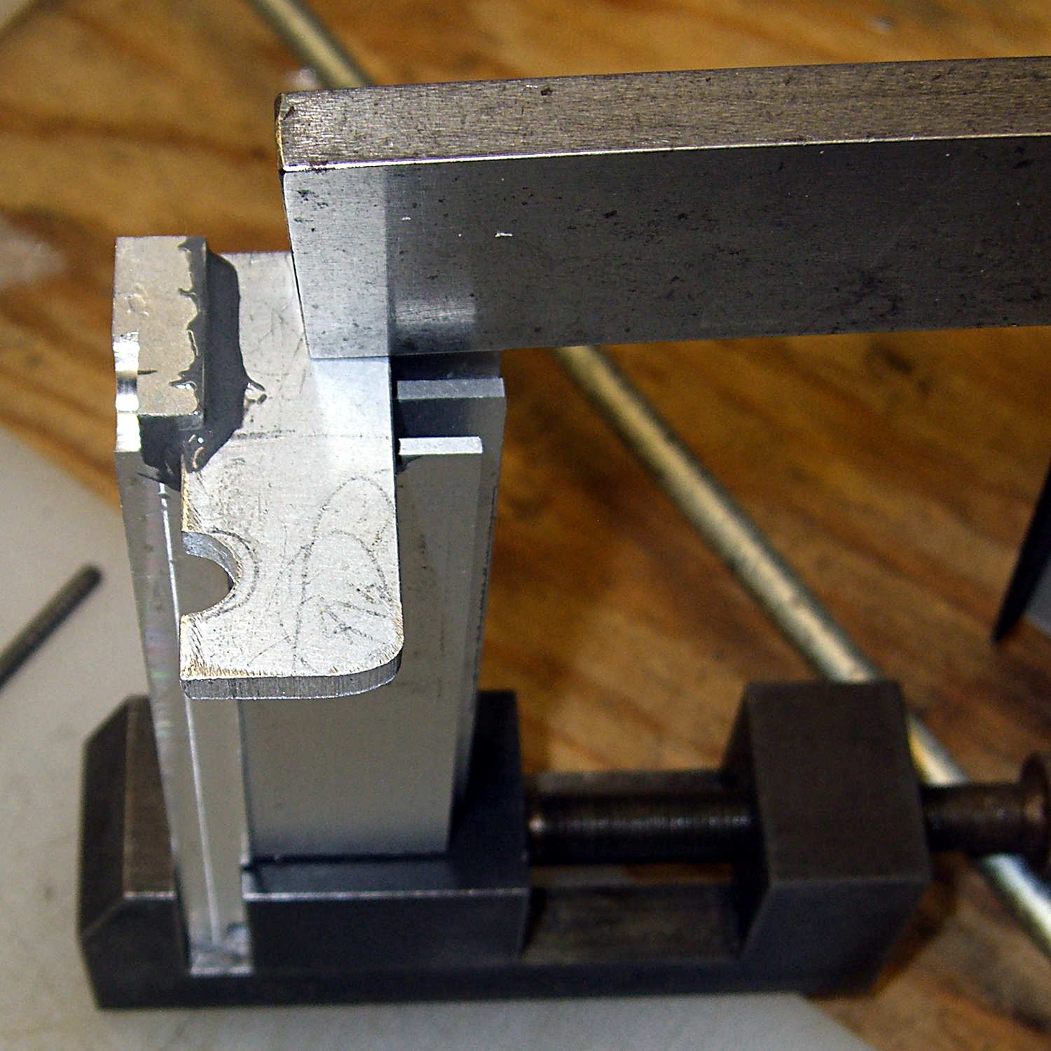
Clamped into the Sherline’s vise, it’s obvious that the slitting saw won’t quite reach all the way through:
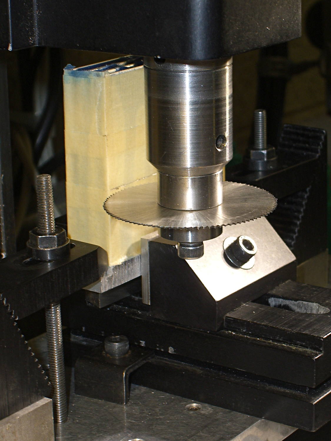
I figured the height by working backwards from the outside of the end cap and forward from the bulkhead at the end of the arm. As it turned out, the middle fins fit and the outer two didn’t, but it was surprisingly close. The length turned out to be spot on, which is the sort of coincidence that tells me I’m on the right track. This is not an exact science.
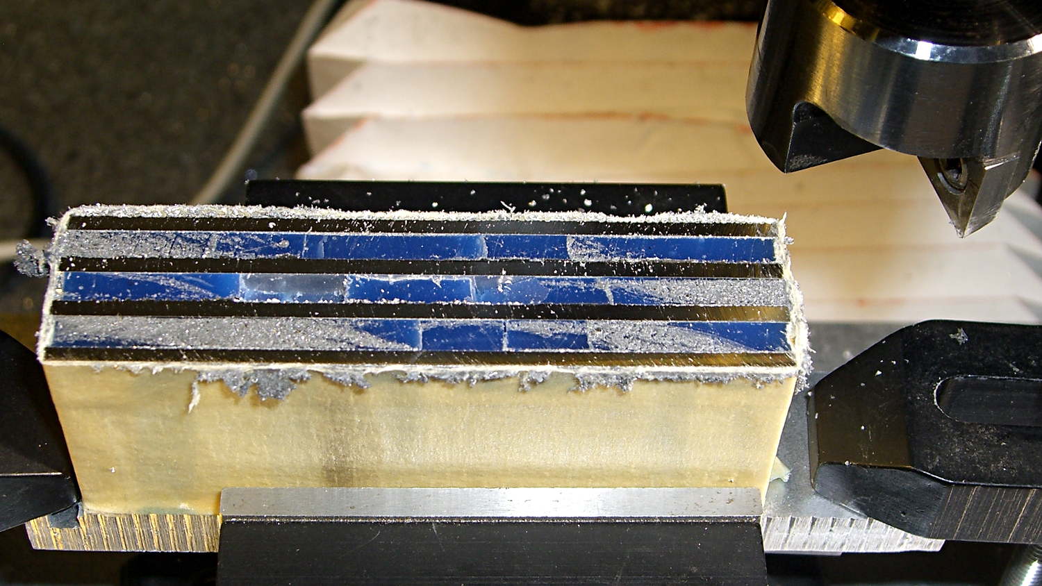
One cut along the front, another along the rear, and the fins popped right off:

Those aren’t broken teeth on the blade, they’re just loaded with wax and aluminum dust.
I love the way Sherline’s little flycutter produces a nice finish with minimal effort:
My plan to secure the heatsink to the sewing machine by repurposing two convenient screws was foiled by the lower screw: it’s too short and sports a fine 6-40 thread. Not only does my heap lack 6-40 screws, Eks doesn’t have any, either; I would have lost big money on that bet.
Brownell’s has a fillister-head screw assortment including 6-40 threads, so that problem will Go Away in short order, but they’re out of stock at the moment. My other Brownell’s assortment (which they no longer carry) includes 5-40 screws, but …
This being a prototype, I simply milled a recess to accommodate the offending screw head:
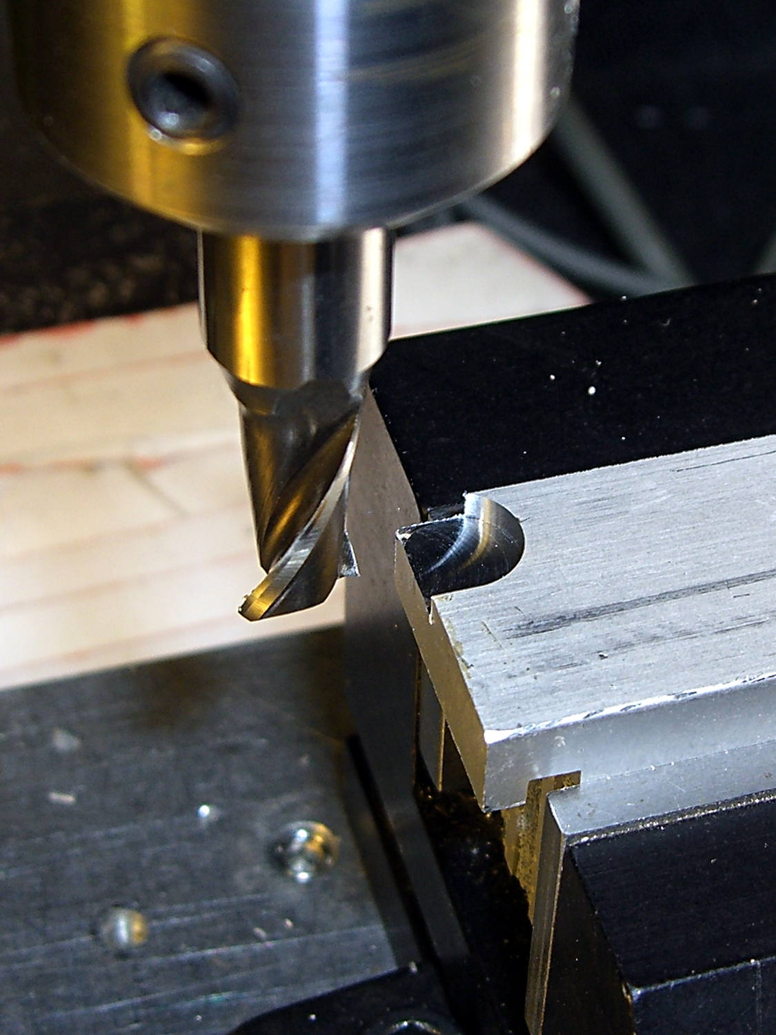
The upper screw originally held the incandescent lamp socket in place and will be long enough to hold the heatsink.
In there somewhere, the ragged bandsawed edge on the far side got itself milled smooth.
Some trial fitting showed the two outer fins must be 2 mm shorter to fit inside the end cap, so the finish on those isn’t nearly as nice:
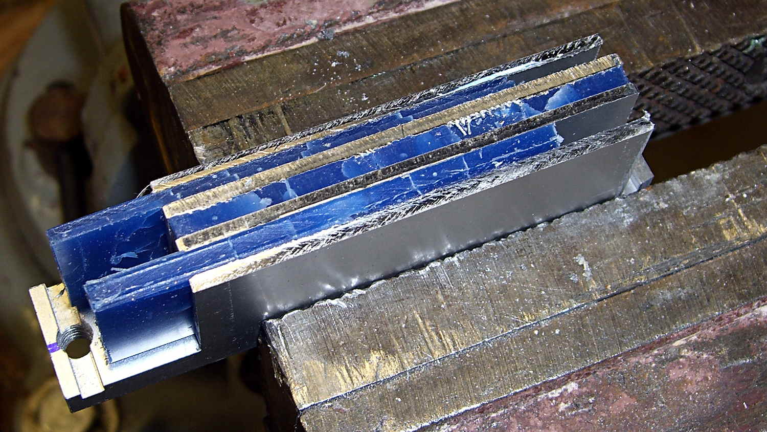
That shows the machinable wax on its way out of the fins, urged along by whacking the ends with a wooden stick. The wax doesn’t adhere to the aluminum and leaves a clean surface, although I’m sure I should scrub it down with solvent to remove any residue.
A bit of paper-doll cutout work provided a shape for the plate that will hold the LEDs, then some bandsaw and hand-filing and milling trimmed it to fit. The heatsink has a slot along the edge, barely visible at the right end of the previous photo, so I hand-filed a rabbet in the plate to let it sit flat against the bottom of the slot and the end of the fins.
Steel-filled epoxy (good old JB Weld) secures the plate and provides good thermal transfer. The steel bar holds the plate against the fins while the epoxy cures:
After some iterative abrasive adjustment on the belt sander, the assembly just barely fits inside the end cap. This view looks through the bobbin access hatch opening in the bed:
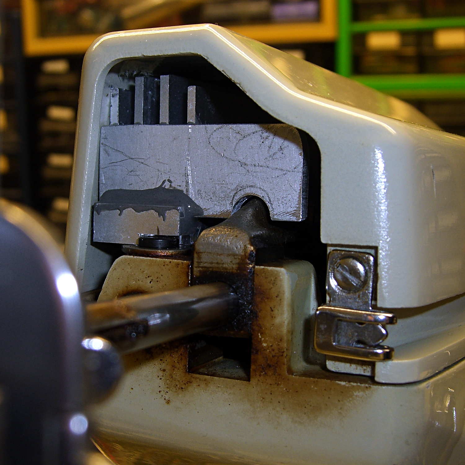
The two outer fins hit various mold sprues / vents / protrusions inside the cast (!) end cap. I think the next version will have three fins, as the cap rides right against the outer fin; the abrasive adjustment came into play on that fin and the end of the LED plate.
The plate could be a bit longer, but let’s see how this one works out.
The notch just barely clears the arm that moves the needle sideways during zig-zag stiches. The rectangular joint guides the arm left-to-right (vertically in this image), but doesn’t slide up-and-down. I think it’s as far out as it’ll ever get, but, again, this is a prototype.
Now, to mount LEDs on that plate…

Comments
3 responses to “Kenmore 158 LED Heatsink: Machinable Wax FTW!”
When I’ve run into situations where I needed to measure odd-shaped interior volumes, where it was simply impossible to get a measuring tool in there, I’ve used play-doh or the like, mooshed it, and then extracted it and worked with the result. Case in point, measuring the clearance between the hood and the valve cover on an engine swap project.
It may come to that, followed by picking squished gumminess out of the hoodickies. There’s a lot of stuff under that cap! [sigh]
[…] bashed a pair of angled brackets from a random heatsink fin to hold the extruder & platform fans […]