|
// Microscope Stage Positioner |
|
// Ed Nisley KE4ZNU January 2016 |
|
|
|
Layout = "Build"; // Show Build |
|
// Base ZStand YMount XMount |
|
|
|
Gap = 0.0; |
|
|
|
//- Extrusion parameters must match reality! |
|
|
|
ThreadThick = 0.25; |
|
ThreadWidth = 0.40; |
|
|
|
HoleWindage = 0.2; |
|
|
|
Protrusion = 0.1; // make holes end cleanly |
|
|
|
inch = 25.4; |
|
|
|
function IntegerMultiple(Size,Unit) = Unit * ceil(Size / Unit); |
|
|
|
//———————- |
|
// Dimensions |
|
|
|
SlipFit = 0.1; |
|
|
|
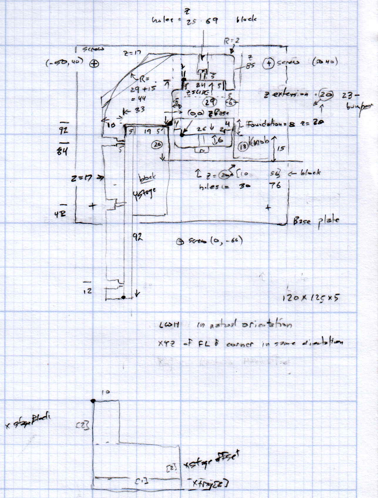
ZDrive = [26.0,19.6,75.0]; // stationary part of Z drive |
|
ZDriveOffset =[0,0,22.0]; // left front corner of stationary Z base |
|
ZWall = 4.0; // thickness of edge wrapped around Z columns |
|
|
|
YStageBlock = [25.0,61.0,17.0]; // Y stage mount + slide |
|
YStageOffset = [-6.0,4.0,0.0]; // offset to inner corner of Y stage holder |
|
|
|
YArm = [10.0,93.0,17.0]; // mount to stationary part of Y stage |
|
|
|
ZStage = [24.0,9.7,85.0]; // moving part of Z drive |
|
ZYArm = [(2*ZWall + ZStage[0]),10.0,YArm[2]]; // attaches to ZStage, same thickness as YArm |
|
|
|
XStageBlock = [25.0,20.0,12.0]; // X stage mount + slide |
|
XStageOffset = [-95.0,-15.0,-26]; // offset to rear left bottom corner of X stage slide |
|
|
|
XTray = [25,25,5]; // X tray attached to bottom of X mount |
|
|
|
//———————- |
|
// Useful routines |
|
|
|
module PolyCyl(Dia,Height,ForceSides=0) { // based on nophead's polyholes |
|
|
|
Sides = (ForceSides != 0) ? ForceSides : (ceil(Dia) + 2); |
|
|
|
FixDia = Dia / cos(180/Sides); |
|
|
|
cylinder(r=(FixDia + HoleWindage)/2, |
|
h=Height, |
|
$fn=Sides); |
|
} |
|
|
|
|
|
//– Z Stand |
|
|
|
module ZStand() { |
|
|
|
Holes = [12.0,41.5,68.0]; |
|
HoleOD = 3.5; |
|
HolesOC = 15.0; |
|
|
|
echo(str("Z Stand holes OC: ",HolesOC)); |
|
|
|
ZPlate = 6.0; // thickness of Z plate = max screw grab distance |
|
ZStandWrap = 2.0; // length of edge wrapped around Z column |
|
|
|
MaxY = 9.0; |
|
MinY = -14.0; |
|
|
|
difference() { |
|
union() { |
|
linear_extrude(height=ZDriveOffset[2]) |
|
polygon(points=[ |
|
[-ZWall,MaxY], // limited by Z slide rack |
|
[ZDrive[0] + ZWall,MaxY], |
|
[ZDrive[0] + ZWall,MinY], // limited by X slide rack |
|
[-ZWall,MinY] |
|
]); |
|
linear_extrude(height=(ZDrive[2] + ZDriveOffset[2]),convexity=4) |
|
polygon(points=[ |
|
[-SlipFit,0], |
|
[ZDrive[0] + SlipFit,0.0], |
|
[ZDrive[0] + SlipFit,ZStandWrap], |
|
[ZDrive[0] + ZWall,ZStandWrap], |
|
[ZDrive[0] + ZWall,-ZPlate], |
|
[-ZWall,-ZPlate], |
|
[-ZWall,ZStandWrap], |
|
[-SlipFit,ZStandWrap] |
|
]); |
|
} |
|
|
|
for (i = [0:len(Holes) – 1]) // holes along Z stand |
|
translate([ZDrive[0]/2,ZDrive[1]/2,(Holes[i] + ZDriveOffset[2])]) |
|
rotate([90,0,0]) |
|
PolyCyl(HoleOD,ZDrive[1]); |
|
|
|
for (i = [-1,1]) // mounting screw holes |
|
translate([i*HolesOC/2 + ZDrive[0]/2, // center the holes from side to side |
|
(MaxY + MinY)/2, // moby hack to put holes on midline |
|
-Protrusion]) |
|
PolyCyl(3.5,0.75*ZDriveOffset[2],6); |
|
} |
|
} |
|
|
|
//– Y Mounting arm |
|
// Polygon origin at inner corner nearest the Z stand column |
|
|
|
module YMount() { |
|
|
|
YHoles = [12.0,48.0,84.0]; // mounting holes along Y stage arm, from outside in |
|
YScrewLength = 4.0; // screw head to Y stage mount |
|
|
|
ZStageBase = [(ZDrive[0] – ZStage[0])/2,(ZDrive[1] + ZStage[1]),0.0] – YStageOffset; // local coordinates of Z slide left rear corner |
|
ZHoles = [26.5,55.0,71.0]; |
|
|
|
ZStageWrap = 8.0; // length of edge wrapped around Z stage |
|
Trim = ZStageBase[1] – ZStageWrap; |
|
|
|
union() { |
|
difference() { |
|
linear_extrude(height=YArm[2],convexity=5) |
|
polygon(points=[ |
|
[-Trim,0.0], |
|
[-YStageBlock[0],0.0], |
|
[-YStageBlock[0],-(YArm[1] + SlipFit)], |
|
[-(YStageBlock[0] + YArm[0]),-(YArm[1] + SlipFit)], |
|
[-(YStageBlock[0] + YArm[0]),Trim], |
|
[-Trim,(ZStageBase[1] + ZYArm[1])], |
|
[(ZStageBase[0] + ZStage[0]/2),(ZStageBase[1] + ZYArm[1])], |
|
[(ZStageBase[0] + ZStage[0] + ZWall),(ZStageBase[1] + 0*ZYArm[1])], |
|
[(ZStageBase[0] + ZStage[0] + ZWall),(ZStageBase[1] – ZStageWrap)], |
|
[(ZStageBase[0] + ZStage[0] + SlipFit),(ZStageBase[1] – ZStageWrap)], |
|
[(ZStageBase[0] + ZStage[0] + SlipFit),ZStageBase[1]], |
|
[(ZStageBase[0] – SlipFit),ZStageBase[1]], |
|
[(ZStageBase[0] – SlipFit),(ZStageBase[1] – ZStageWrap)], |
|
[0.0,(ZStageBase[1] – ZStageWrap)], |
|
[0.0,Trim] |
|
]); |
|
|
|
for (j=[0:len(YHoles) – 1]) { // Y stage mounting screws |
|
translate([-(YStageBlock[0] + YScrewLength), |
|
(-YArm[1] + YHoles[j] – 2*SlipFit), |
|
YArm[2]/2]) |
|
rotate([0,-90,0]) rotate(180/6) |
|
PolyCyl(5.5,YArm[0],6); |
|
translate([-(YStageBlock[0] – Protrusion), |
|
(-YArm[1] + YHoles[j] – 2*SlipFit), |
|
YArm[2]/2]) |
|
rotate([0,-90,0]) rotate(180/6) |
|
PolyCyl(2.5,2*YArm[0],6); |
|
} |
|
} |
|
if (true) |
|
difference() { |
|
linear_extrude(height=ZStage[2],convexity=5) |
|
polygon(points=[ |
|
[(ZStageBase[0] – ZWall),(ZStageBase[1] + 5.0)], |
|
[(ZStageBase[0] + ZStage[0] + ZWall),(ZStageBase[1] + 5.0)], |
|
[(ZStageBase[0] + ZStage[0] + ZWall),(ZStageBase[1] – ZStageWrap)], |
|
[(ZStageBase[0] + ZStage[0] + SlipFit),(ZStageBase[1] – ZStageWrap)], |
|
[(ZStageBase[0] + ZStage[0] + SlipFit),ZStageBase[1]], |
|
[(ZStageBase[0] – SlipFit),ZStageBase[1]], |
|
[(ZStageBase[0] – SlipFit),(ZStageBase[1] – ZStageWrap)], |
|
[(ZStageBase[0] – ZWall),(ZStageBase[1] – ZStageWrap)], |
|
]); |
|
for (k=[0:len(ZHoles) – 1]) |
|
translate([(ZStageBase[0] + ZStage[0]/2),0.0,ZHoles[k]]) |
|
rotate([-90,0,0]) |
|
PolyCyl(3.5,2*ZStageBase[1],6); |
|
} |
|
} |
|
} |
|
|
|
//– X Slide attachment |
|
// Origin at left rear bottom of mount |
|
|
|
module XMount() { |
|
|
|
XHoles = [6.0,18.0]; // from end of X slide |
|
XHolesOffset = 7.0; // from bottom of X slide |
|
|
|
TrayHolesOC = 10.0; |
|
echo(str("Tray holes OC: ",TrayHolesOC)); |
|
|
|
BlockOAH = XStageBlock[2] – XStageOffset[2] – XTray[2]; // overall height of mount |
|
|
|
difference() { |
|
translate([XStageBlock[0],0,BlockOAH]) |
|
rotate([0,90,180]) |
|
linear_extrude(height=XStageBlock[0],convexity=2) |
|
polygon(points=[ |
|
[0,0], |
|
[0.0,7.0], |
|
[(XStageBlock[2] + SlipFit),7.0], |
|
[(XStageBlock[2] + SlipFit),XStageBlock[1]], |
|
[BlockOAH,XStageBlock[1]], |
|
[BlockOAH,0.0], |
|
]); |
|
|
|
for (i=[0:len(XHoles) – 1]) // holes for X stage screws |
|
translate([XHoles[i],Protrusion,BlockOAH – XStageBlock[2] + XHolesOffset]) |
|
rotate([90,0,0]) |
|
PolyCyl(3.5,2*7.0,6); |
|
|
|
for (i=[-1,1]) // holes for tray mount |
|
translate([i*TrayHolesOC/2 + XStageBlock[0]/2,-XStageBlock[1]/2,-Protrusion]) |
|
PolyCyl(2.5,0.75*(BlockOAH – XStageBlock[2]),6); |
|
} |
|
|
|
} |
|
|
|
//———————- |
|
// Build it |
|
|
|
if (Layout == "ZStand") |
|
ZStand(); |
|
|
|
if (Layout == "YMount") |
|
YMount(); |
|
|
|
if (Layout == "XMount") |
|
XMount(); |
|
|
|
|
|
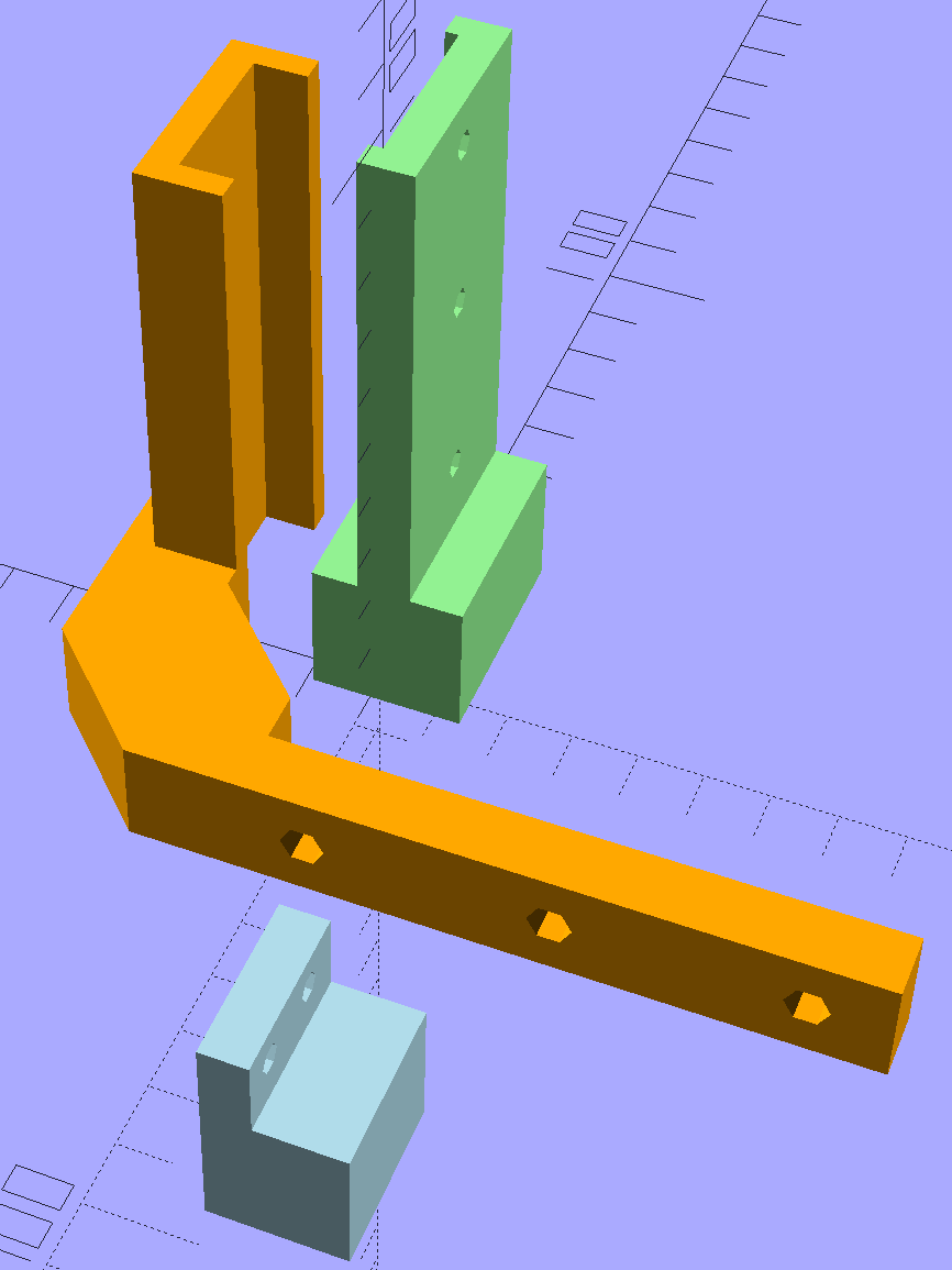
if (Layout == "Show") { |
|
|
|
color("lightgreen") |
|
ZStand(); |
|
|
|
color("orange") |
|
translate(YStageOffset) |
|
YMount(); |
|
|
|
color("lightblue") |
|
translate(XStageOffset + [0,0,-XStageOffset[2]]) |
|
XMount(); |
|
} |
|
|
|
if (Layout == "Build") { |
|
|
|
translate([20,0,0]) |
|
ZStand(); |
|
|
|
translate([YStageBlock[0]/2,0,0]) |
|
YMount(); |
|
|
|
translate([20,-30,0]) |
|
XMount(); |
|
} |