The HP 7475A plotter comes with a transparent smoke-brown plastic flip-up lid covering the carousel and pen holder, presumably to keep dust and fingers out of the moving parts. That lid also has has the side effect of limiting the pen length, presumably because HP didn’t want the 7475A to eat into their large-format plotter market. In any event, removing the lid leaves another barrier to longer pens: the rugged plastic case between the carousel and the pen holder.
Well, seeing as how this puppy has been fully depreciated, a bit of pull saw work opened that opportunity:

Despite appearances, all six Sakura Micron pens emerge vertical & parallel from their adapters in the carousel:

They pass neatly through the new channel:

And produce reasonable lines, with motion blur catching the pen holder in the midst of a pen-up / pen-down twitch:

That’s from an earlier test, before I sawed the slot in the case, with all the machinery behind the pen holder in full view.
The test plot, with the proper pen colors and widths loaded in the carousel, looks pretty good:

The pen holder wasn’t intended to support a long pen, so that shaft tends to torque the pen tip out of position, particularly while drawing characters:

The various pen tips don’t all point to the same place:
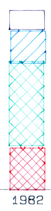
That could be non-concentric pen adapters, misalignment in the pen holder, or slightly off-center pen nibs. The offsets between the colors remains consistent in all the bar-chart columns, so the pen adapters aren’t shifting in the holder.
The worst-case error between bar-chart rectangles amounts to 0.5 mm parallel to the pen holder motion and 0.8 mm parallel to the paper motion. In round numbers, the pen tip is 30 mm from the flange, so moving it 0.5 mm to the side tips the pen 1°. The flange is 17 mm OD, which means a 1° tilt raises one edge by 0.3 mm or both edges by ±0.15 mm. Given a 0.25 mm 3D printed thread thickness, that’s certainly within reach of a random plastic blob.
Looking closely at the printed-and-glued flange shows plenty of room for misunderstanding betwixt pen and holder, even after cleaning off all that PETG hair:

Given that the Sakura pens aren’t intended for this application, a slight tip misalignment due to body molding tolerances isn’t unreasonable; a perfect adapter might not solve the problem.
The HP maintenance manual lists a BASIC program to produce a test plot that verifies pen alignment, although the prospect of transliterating 2+ pages of quoted strings from a scanned document doesn’t fill me with desire.

Comments
7 responses to “HP 7475A Plotter: Full-up Sakura Micron Pen Tests”
Question: How machinable is the PETG, as in using a(n overly complex) reamer/boring setup to clean out the cruft? I’m wondering if it’s feasible to rough-print stuff and finish them, reminiscent of castings.
I chucked up the steel mandrel and tried turning the exterior of a few adapters, but plastic-on-steel doesn’t have quite enough traction. If I had an expanding mandrel, maybe something with rubberdraulic plugs, it would work great!
Sanding PETG works moderately well, although you really should paint the surface afterward for better looks. Rumor has it you can flame-polish PETG, which sounds exciting.
My usual brackets, printed with 1 to 2 mm of solid perimeters, would have plenty of room for finish machining. Those thin cylinders don’t have much meat; if I did an expanding mandrel, adding 1 mm to the OD should suffice.
Measure the error for each pen and adjust the holder model to compensate?
That’d definitely be easier than adjusting the HPGL coordinate stream based on the selected pen… [grin]
HP offered a few different carousels for that plotter, I wonder if a different one would be easier to integrate with.
http://h20564.www2.hp.com/hpsc/doc/public/display?docId=emr_na-bpp01366
A quick search says the 07475-60030 liquid ink carousel flat-out isn’t available, which simply means one will pop up on eBay tomorrow…
I betcha the only difference is how the (now missing) rubber boots wrap around the pen tip.
[…] ink pens with contents ranging from desiccated to gummy. With nothing to lose (and having already cut a clearance slot in the plotter case), I drilled a small hole in the top of each reservoir, squirted some inkjet printer ink into the […]