The Smell of Molten Projects in the Morning

Ed Nisley's Blog: Shop notes, electronics, firmware, machinery, 3D printing, laser cuttery, and curiosities. Contents: 100% human thinking, 0% AI slop.

Tag: Sherline

Sherline CNC mill

  • CNC 3018-Pro: Platter Fixtures

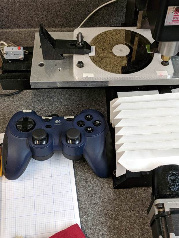
    Up to this point, the Sherline has been drilling 3.5 inch hard drive platters to serve as as reflecting bases for the vacuum tubes:

    LinuxCNC - Sherline Mill - Logitech Gamepad
    LinuxCNC – Sherline Mill – Logitech Gamepad

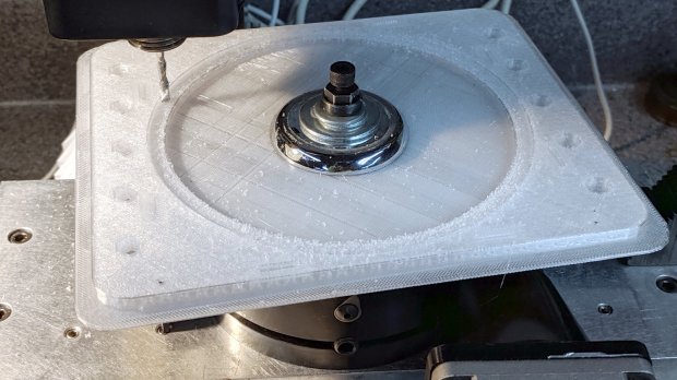
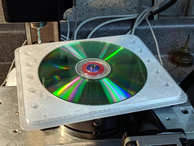
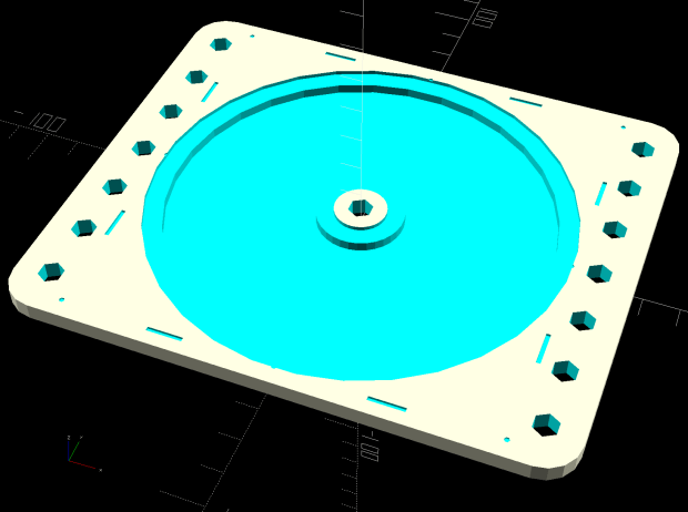
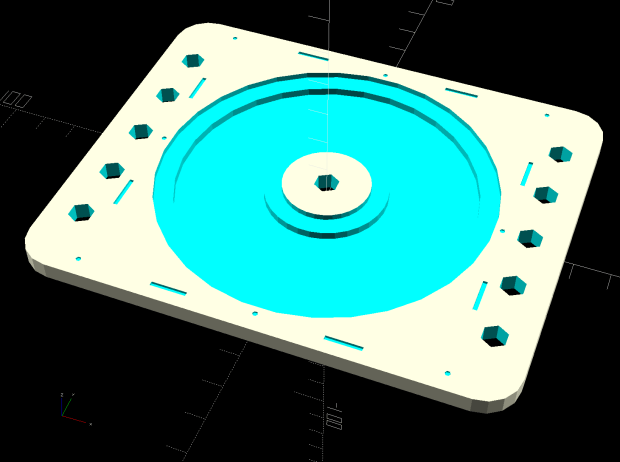
    The CNC 3018-Pro has a work envelope large enough for CD / DVD platters, so I mashed the Sherline fixture with dimensions from the vacuum tube code, added the 3018’s T-slot spacing, and conjured a pair of fixtures for a pair of machines.

    Because I expect to practice on scrap CDs and DVDs for a while:

    Platter Fixtures - CD on 3018
    Platter Fixtures – CD on 3018

    And a 3.5 inch hard drive platter version:

    Platter Fixtures - hard drive platter on 3018
    Platter Fixtures – hard drive platter on 3018

    The holes sit at half the 3018’s T-slot spacing (45 mm / 2), so you can nudge the fixtures to the front or rear, as you prefer.

    The alignment dots & slots should help touch off the XY coordinate system on the Sherline, although it can’t reach all of a CD. Using bCNC’s video alignment on the hub hole will be much easier on the 3018.

    After fiddling around with the 3018 for a while, however, the CD fixture doesn’t have many advantages over simply taping the disc to a flat platen. Obviously, you’d want a sacrificial layer for drilling, but it’s not clear the OEM motor / ER11 chuck would be up to that task.

    The OpenSCAD source code as a GitHub Gist:

    // Machining fixtures for CD and hard drive platters
    // Ed Nisley KE4ZNU February … September 2016
    // 2019-08 split from tube base models
    PlatterName = "CD"; // [3.5inch,CD]
    CNCName = "3018"; // [3018,Sherline]
    PlateThick = 5.0; // [5.0,10.0,15.0]
    RecessDepth = 4.0; // [0.0,2.0,4.0]
    //- Extrusion parameters must match reality!
    /* [Hidden] */
    ThreadThick = 0.25;
    ThreadWidth = 0.40;
    HoleWindage = 0.2;
    Protrusion = 0.1; // make holes end cleanly
    inch = 25.4;
    function IntegerMultiple(Size,Unit) = Unit * ceil(Size / Unit);
    module PolyCyl(Dia,Height,ForceSides=0) { // based on nophead's polyholes
    Sides = (ForceSides != 0) ? ForceSides : (ceil(Dia) + 2);
    FixDia = Dia / cos(180/Sides);
    cylinder(d=(FixDia + HoleWindage),h=Height,$fn=Sides);
    }
    ID = 0;
    OD = 1;
    LENGTH = 2;
    //———————-
    // Dimensions
    P_NAME = 0; // platter name
    P_ID = 1; // … inner diameter
    P_OD = 2; // … outer diameter
    P_THICK = 3; // … thickness
    PlatterData = [
    ["3.5inch", 25.0, 95.0, 1.75],
    ["CD", 15.0, 120.0, 1.20],
    ];
    PlatterSides = 3*4*5; // polygon approximation
    B_NAME = 0; // machine name
    B_OC = 1; // … platform screw OC, use small integer for slot
    B_STUD = 2; // … screw OD clearance
    BaseData = [
    ["3018", [5.0, 45.0], 6.0], // slots along X axis
    ["Sherline", [1.16*inch,1.16*inch], 5.0], // tooling plate
    ];
    //———————-
    // Drilling fixture for disk platters
    module PlatterFixture(Disk,Machine) {
    PI = search([Disk],PlatterData,1,0)[P_NAME]; // get platter index
    echo(str("Platter: ",Disk));
    Platter = [PlatterData[PI][P_ID],
    PlatterData[PI][P_OD],
    PlatterData[PI][P_THICK]];
    BI = search([Machine],BaseData,1,0)[B_NAME]; // get base index
    echo(str("Machine: ",Machine));
    AlignOC = IntegerMultiple(Platter[OD],10);
    echo(str("Align OC: ",AlignOC));
    AlignSlot = [3*ThreadWidth,10.0,3*ThreadThick];
    StudClear = BaseData[BI][B_STUD]; // … clearance
    StudOC = [IntegerMultiple(AlignOC + 2*StudClear,BaseData[BI][B_OC].x), // … screw spacing
    BaseData[BI][B_OC].y];
    echo(str("Stud spacing: ",StudOC));
    NumStuds = [2,1 + 2*floor(Platter[OD] / StudOC.y)]; // holes only along ±X edges
    echo(str("Stud holes: ",NumStuds));
    BasePlate = [(20 + StudOC.x*ceil(Platter[OD] / StudOC.x)),
    (10 + AlignOC),
    PlateThick];
    echo(str("Plate: ",BasePlate));
    PlateRound = 10.0; // corner radius
    difference() {
    hull() // basic plate shape
    for (i=[-1,1], j=[-1,1])
    translate([i*(BasePlate.x/2 – PlateRound),j*(BasePlate.y/2 – PlateRound),0])
    cylinder(r=PlateRound,h=BasePlate.z,$fn=4*4);
    for (i=[-1,0,1], j=[-1,0,1]) // origin pips
    translate([i*AlignOC/2,j*AlignOC/2,BasePlate.z – 2*ThreadThick])
    cylinder(d=4*ThreadWidth,h=1,$fn=6);
    for (i=[-1,1], j=[-1,1]) { // alignment slots
    translate([i*(AlignOC + AlignSlot.x)/2,
    j*Platter[OD]/4,
    (BasePlate.z – AlignSlot.z/2 + Protrusion/2)])
    cube(AlignSlot + [0,0,Protrusion],center=true);
    translate([i*Platter[OD]/4,
    j*(AlignOC + AlignSlot.x)/2,
    (BasePlate.z – AlignSlot.z/2 + Protrusion/2)])
    rotate(90)
    cube(AlignSlot + [0,0,Protrusion],center=true);
    }
    for (i=[-1,1], j=[-floor(NumStuds.y/2):floor(NumStuds.y/2)]) // mounting stud holes
    translate([i*StudOC.x/2,j*StudOC.y/2,-Protrusion])
    rotate(180/6)
    PolyCyl(StudClear,BasePlate.z + 2*Protrusion,6);
    translate([0,0,-Protrusion]) // center clamp hole
    rotate(180/6)
    PolyCyl(StudClear,BasePlate.z + 2*Protrusion,6);
    translate([0,0,BasePlate.z – Platter[LENGTH]]) // disk locating recess
    rotate(180/PlatterSides)
    linear_extrude(height=(Platter[LENGTH] + Protrusion),convexity=2)
    difference() {
    circle(d=(Platter[OD] + HoleWindage),$fn=PlatterSides);
    circle(d=Platter[ID] – HoleWindage,$fn=PlatterSides);
    }
    translate([0,0,BasePlate.z – RecessDepth]) // drilling recess
    rotate(180/PlatterSides)
    linear_extrude(height=(RecessDepth + Protrusion),convexity=2)
    difference() {
    circle(d=(Platter[OD] – 10),$fn=PlatterSides);
    circle(d=(Platter[ID] + 10),$fn=PlatterSides);
    }
    }
    }
    //———————-
    // Build it
    PlatterFixture(PlatterName,CNCName);

  • Kinesis Freestyle 2: Steel Tactile Bumps

    Adding tape bumps to the worn Kinesis keyboard demonstrated I really need tactile home keys, so I popped the tops and fired up the Sherline mill:

    Kinesis keyboard - 2 mm drilling
    Kinesis keyboard – 2 mm drilling

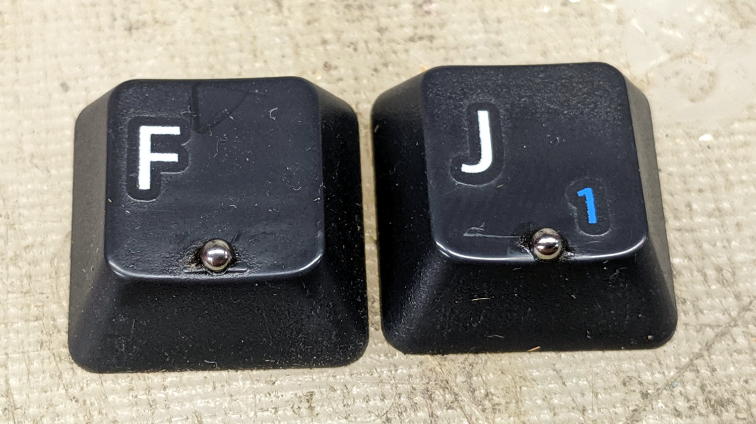
    That’s a genuine 2 mm carbide end mill, poked 1 mm into the key cap, snuggled right up against the front edge.

    Two epoxy dabs and some wiping later:

    Kinesis keyboard - 2 mm tactile bearings
    Kinesis keyboard – 2 mm tactile bearings

    The careful alignment on the F key tells you I did it first; obviously, I should make better fixtures.

    The holes could be slightly larger and maybe slightly deeper, but the bearings feel just right.

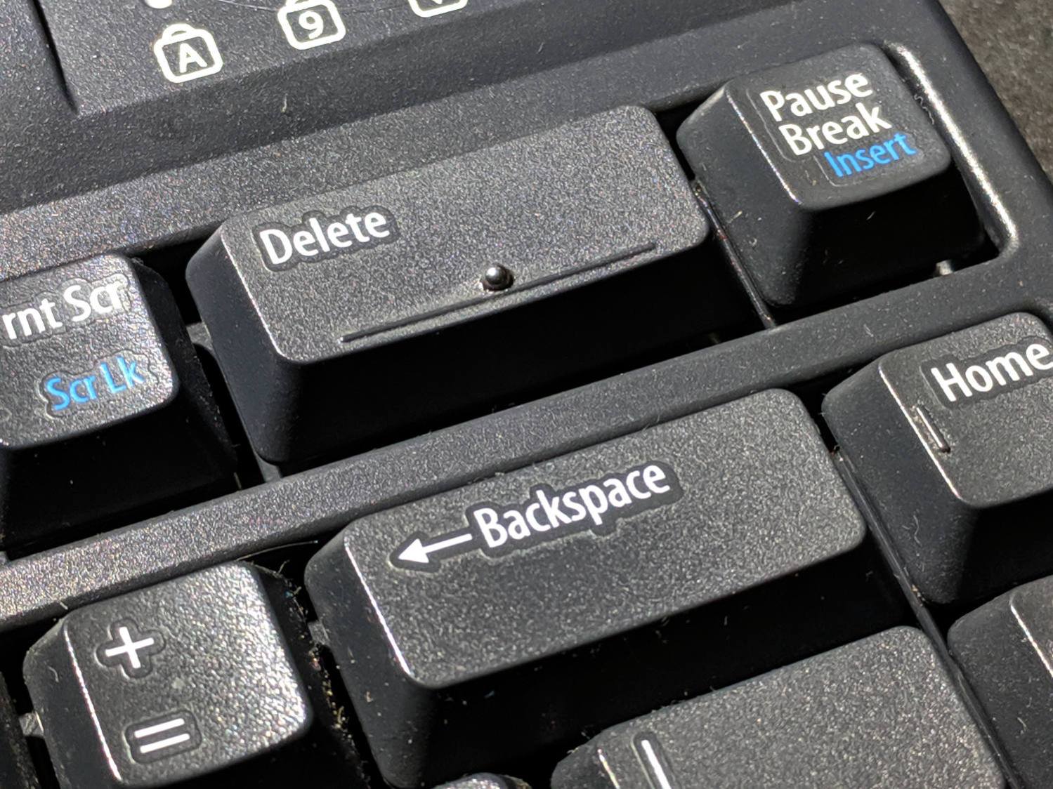
    Indeed, they work so well a ball now distinguishes the far-flung Delete and Backspace keys:

    Kinesis keyboard - 2 mm bearing - Delete key
    Kinesis keyboard – 2 mm bearing – Delete key

    Now, to see how long the epoxy lasts …

  • Mini-Lathe Cut-Off Tool Holder: Improved Clamp Screw

    Apparently all mini-lathe cut–off tool holders suffer from the same problem:

    Lathe Cutoff Tool - OEM swaged screw
    Lathe Cutoff Tool – OEM swaged screw

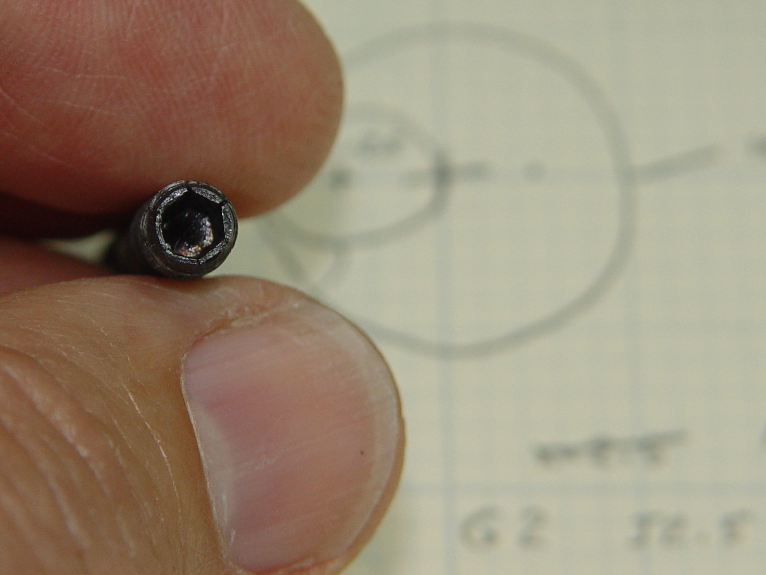
    The clamp tightening screw is made from butter-soft Chinese steel with a swaged hex socket. As you’d expect, the hex wrench eventually (as in, after a few dozen adjustments, tops) rips the guts right out of the socket.

    The screw has a M6×1.0 mm threads, but the thread around the hex recess is left-handed. While I could, in principle, print a 127 tooth change gear, rebuild the lathe’s banjo to accommodate it, then single-point a backassward M6 thread, it’s easier to just use a standard socket head cap screw:

    Lathe Cutoff Tool - rebuilt screw
    Lathe Cutoff Tool – rebuilt screw

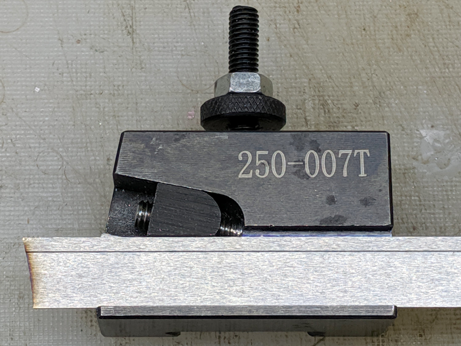
    The clamp screw passes through the block at an angle:

    Lathe Cutoff Tool - blade view
    Lathe Cutoff Tool – blade view

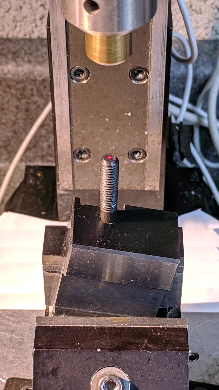
    Fortunately, the screw is perpendicular to the angled side over on the left, making it easy to clamp in the Sherline’s vise:

    Lathe Cutoff Tool - aligning to screw
    Lathe Cutoff Tool – aligning to screw

    Using the laser aligner seemed like a good idea at the time, but the top of the screw wasn’t particularly well-centered on the hole’s axis. I couldn’t screw the left-hand part (with the socket) in from the bottom and center the block near its surface, because then I couldn’t extract the screw before proceeding.

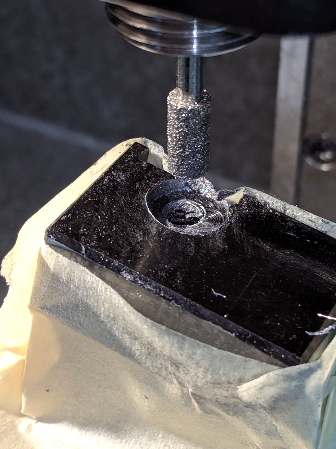
    I used a diamond burr to grind out a flat for the screw head:

    Lathe Cutoff Tool - clearing screw recess
    Lathe Cutoff Tool – clearing screw recess

    The flat came from about twenty manual G2 I-2.5 full-circle passes, stepping down through the hard steel block 0.1 mm per pass, at a too-slow 4000 RPM and a too-fast 30 mm/min feed, with plenty of water squirted from one side into a shop vac snout on the other. The doodle in the background of the first picture shows a first pass at the layout, with the burr centered at X=-2.5; I actually did the grinding from X=+2.5 so most of the passes started in thin air.

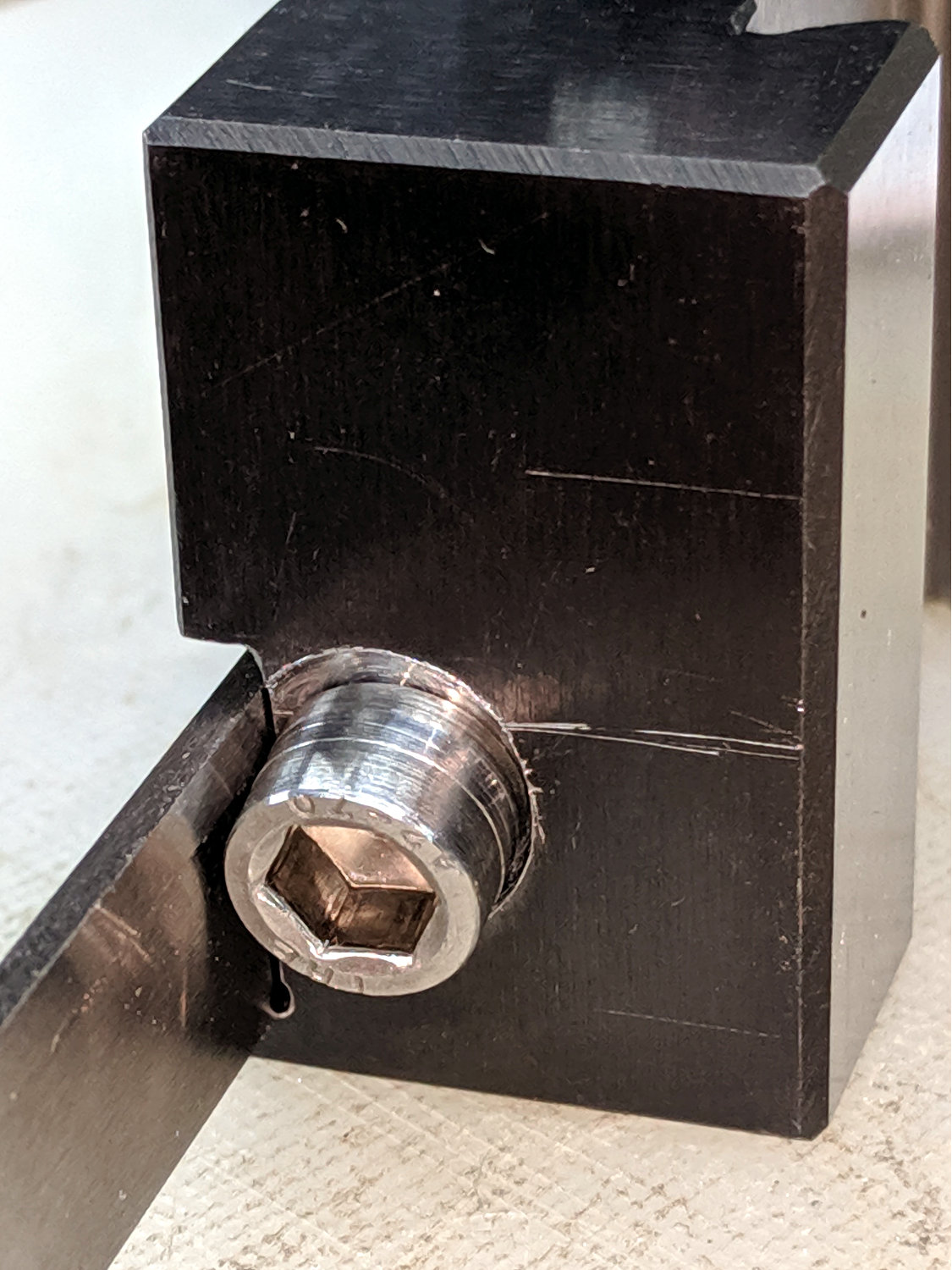
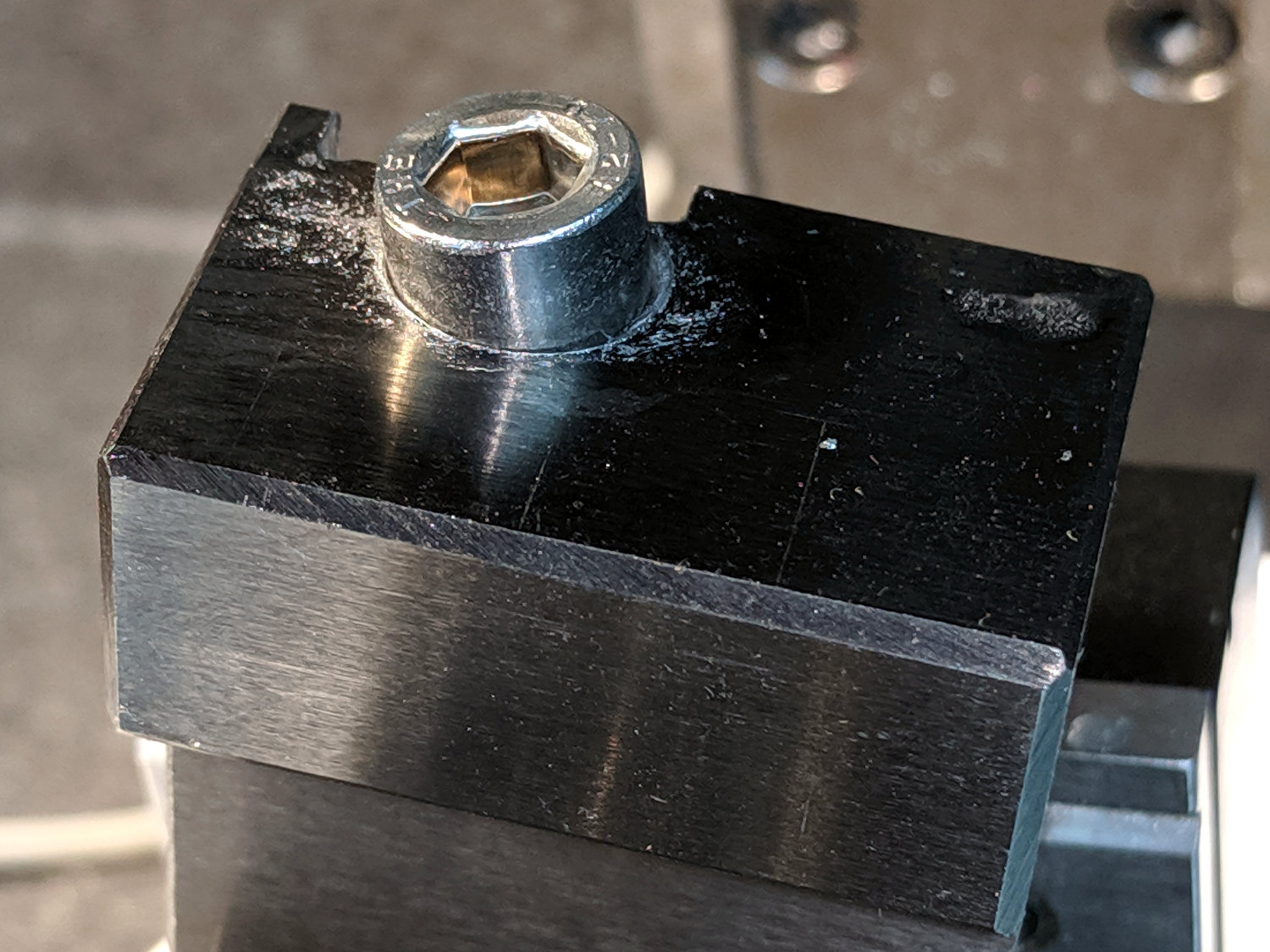
    The screw head started just shy of 10 mm OD and the burr just over 5.2 mm, so the ensuing 5 mm circles created a flat barely large enough. If the flat were perfectly centered on the screw axis, I wouldn’t have had to grind out another millimeter on the left side (toward the bottom of the tool holder body), but it worked out OK:

    Lathe Cutoff Tool - 6 mm SHCS test fit
    Lathe Cutoff Tool – 6 mm SHCS test fit

    The trial fitting also showed the head stuck out ever so slightly beyond the far side of the block, where it would interfere with the blade, so I turned off 0.4 mm off its OD.

    If I had a 50 mm SHCS in hand, I’d have used it. Instead, I extended the threads of a 75 mm screw, then lopped off the end to the proper length. I’ll spare you the ordeal, including the moment when I reached for the cutoff tool to shorten the screw. A bag of such screws will arrive shortly, in preparation for future need.

    Now the [deleted] cut-off holder works the way it should have from the beginning.

  • Drag Knife Blade Ejector Handle

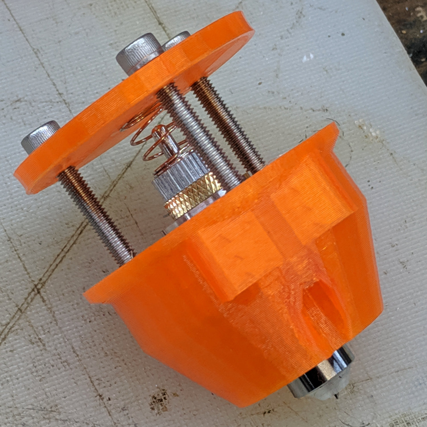
    The LM12UU drag knife holder buries the blade ejector pin deep inside the machinery:

    Drag Knife - LM12UU ground shaft - assembled
    Drag Knife – LM12UU ground shaft – assembled

    So a handle with a pin makes sense:

    LM12UU Drag Knife Ejector Pin Pusher
    LM12UU Drag Knife Ejector Pin Pusher

    It’s a variant Sherline tommy bar handle, so there’s not much to say about it.

    The dark butt end comes from the traces of the black filament I used for the previous part. Even after flushing half a meter of orange through the hot end, you’ll still see some contamination, even with the same type of plastic. Doesn’t make much difference here, though.

  • Sony NP-FM50 Battery Disassembly

    Having won an eBay action for a known-dead Sony DSC-F717 at $0.99 (plus $15 shipping, the seller being no fool), I now have a possibly salvageable camera, a Genuine Sony AC supply, and two more NP-FM50 batteries for about the price of any one of the components.

    One battery arrived stone-cold dead, suggesting the camera had been put away with the battery installed for a very long time and they died companionably. The camera still charges a (good) battery, even though it doesn’t turn on, and perusing the schematics suggests checking the power switch, because it’s always the switch contacts. That’s for another day, though.

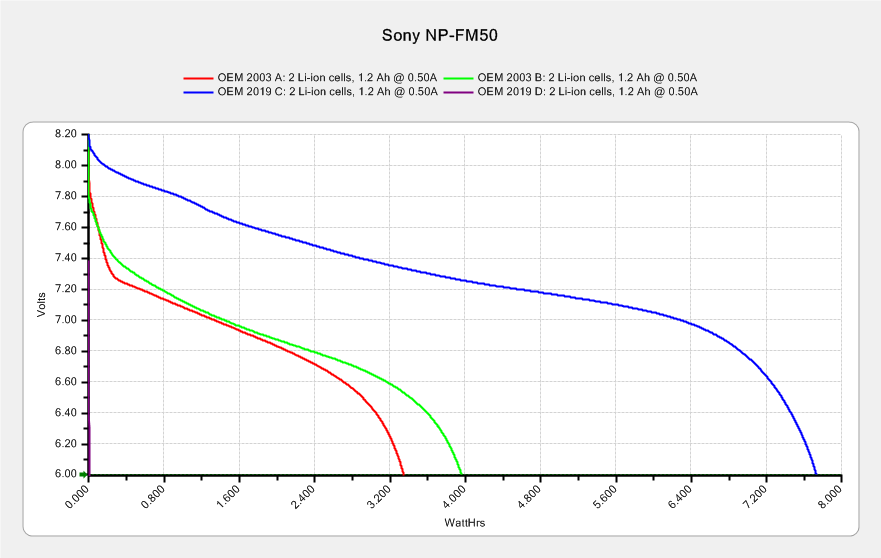
    For the record, the battery status:

    NP-FM50 - 2019-03-30
    NP-FM50 – 2019-03-30

    The red and green traces come from the two batteries I’ve been cycling through the camera since, um, 2003, so they’re getting on in years and correspondingly low in capacity.

    The fourth battery (2019 D, the date showing when it arrived, not its manufacturing date) went from “fully charged” to “dead” in about three seconds with a 500 mA load, producing the nearly invisible purple trace dropping straight down along the Y axis.

    Sawing the dead battery case around its welded joint at a depth of 0.75 mm, then prying with a small chisel, exposed the contents without histrionics:

    Sony NP-FM50 battery - cell label
    Sony NP-FM50 battery – cell label

    Now, there’s a name to conjure with. Turns out Sony sold off its Fukushima battery business a while back, so these must be collectibles. Who knew?

    The lower cell is lifeless, the upper cell may still have some capacity. Three pairs of 18500 lithium cells are on their way, in the expectation of rebuilding the weakest packs.

    After desoldering the battery tab on the right from the PCB, it occurred to me I needed pictures:

    Sony NP-FM50 battery - PCB exposed
    Sony NP-FM50 battery – PCB exposed

    Yeah, that’s a nasty melted spot on the case, due to inept solder-wickage.

    Unsoldering the three tabs closest to the case releases the cells + PCB from confinement:

    Sony NP-FM50 battery - PCB overview
    Sony NP-FM50 battery – PCB overview

    I’m still bemused by battery packs with a microcontroller, even though all lithium packs require serious charge controllers. At least this is an Atmel 8-bitter, rather than 32-bit ARM hotness with, yo, WiFi.

    The cells have shaped tabs which will require some gimmicking to reproduce:

    Sony NP-FM50 battery - cell tabs
    Sony NP-FM50 battery – cell tabs

    Now, if only I could reboot the camera …

  • Multimeter Probe Cable: FAIL

    A reasonably good silicone-wire multimeter probe set arrived last spring and has worked well enough (I thought, anyhow) for the usual voltage measurements, but recently failed while measuring a small current. We all know how this will turn out, but the details may be of some interest.

    Measuring the resistance from tip to plug located the fault to the black probe, after which I poked a pin through the insulation near the plug:

    Multimeter probe - diagnosis
    Multimeter probe – diagnosis

    The two leads near the bottom go to my shiny Siglent bench multimeter. Despite their similarity to the failed probes, I’m pretty sure Siglent has better QC (well, mostly).

    The probe’s resistance was near zero from the tip (offscreen to the left) to the pin and megohms from pin to plug (on the right). Figuring the wire worked loose, I pulled it away from the plug:

    Multimeter probe - disassembly 1
    Multimeter probe – disassembly 1

    Huh.

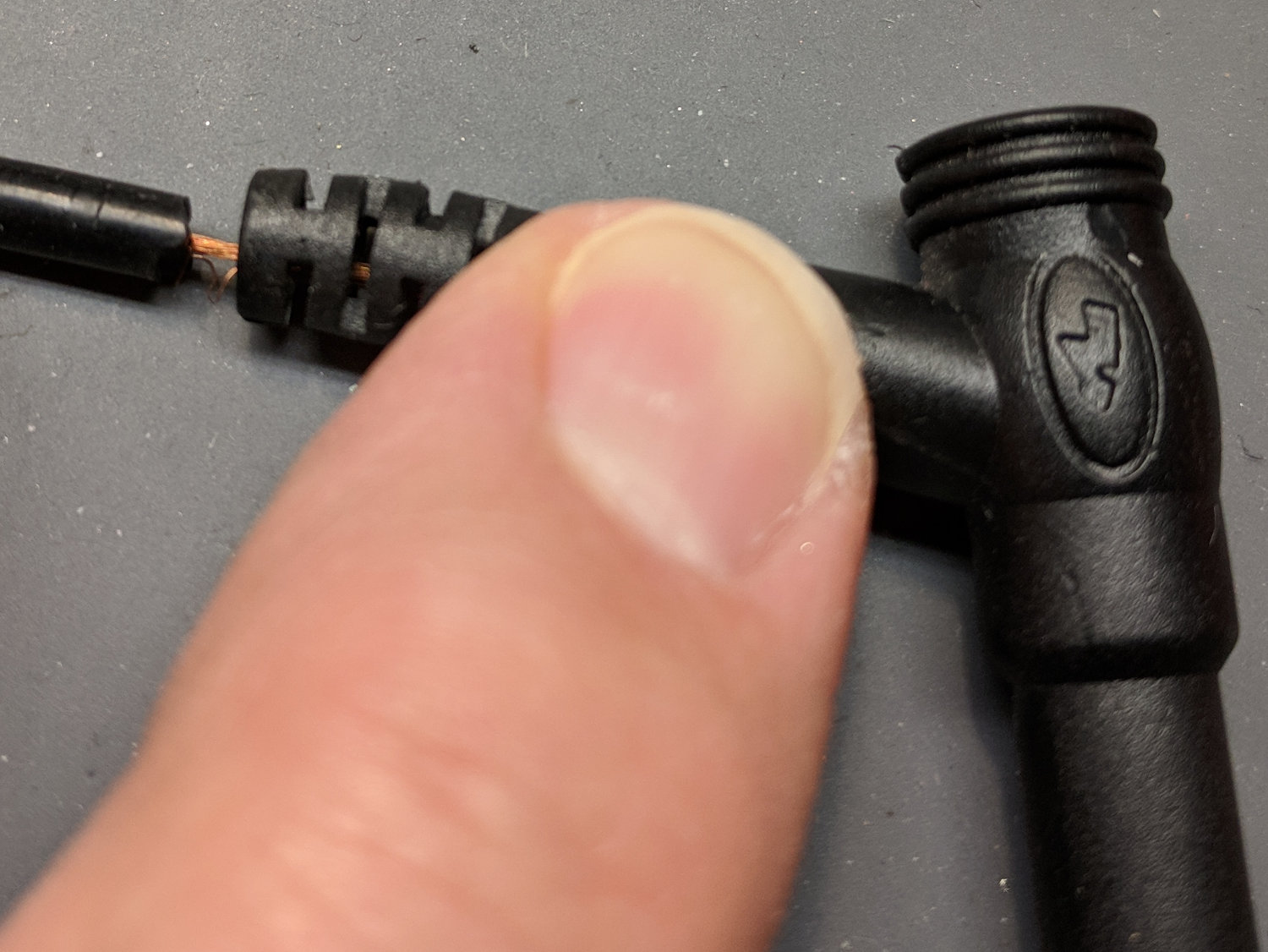
    Although I wouldn’t have trusted those probes anywhere near their alleged 1 kV rating, seeing that exposed copper-like substance was disconcerting.

    Hacking off the strain relief bushing around the wire got closer to the fault:

    Multimeter probe - disassembly 2
    Multimeter probe – disassembly 2

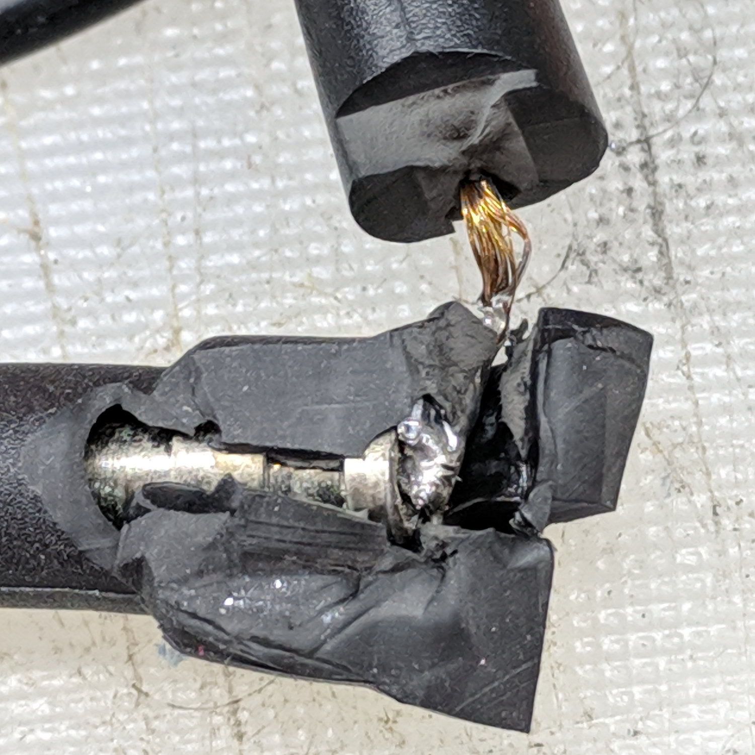
    And, finally, the problem becomes obvious:

    Multimeter probe - disassembly 3
    Multimeter probe – disassembly 3

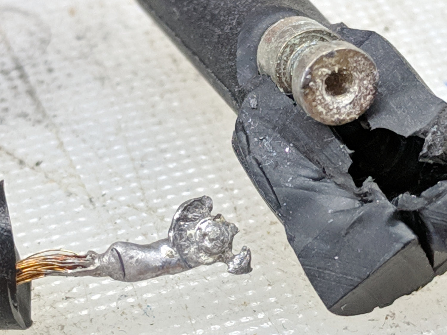
    Yet Another Cold Solder Joint:

    Multimeter probe - cold solder joint
    Multimeter probe – cold solder joint

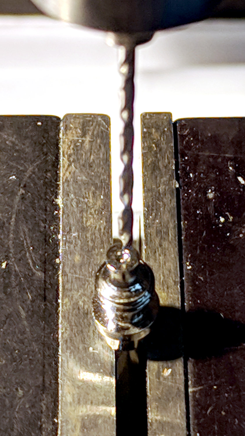
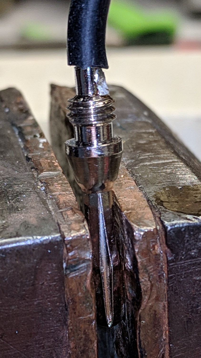
    Pulling a black banana plug from the heap, I decided to drill a proper hole to anchor the wire:

    Multimeter probe - drilling plug
    Multimeter probe – drilling plug

    Which looked like this afterward:

    Multimeter probe - soldered plug
    Multimeter probe – soldered plug

    And produced a strongly mismatched pair:

    Multimeter probe - repaired
    Multimeter probe – repaired

    Ain’t it amazing how much fun you can have for a few bucks, all delivered by eBay? [sigh]

  • Astable Multivibrator: RGB LED Strut Fixture

    One cannot (or, perhaps, should not attempt to) solder parts to 14 AWG wires seated in a 3D printed battery holder base, so I cleaned up the edges of two polycarbonate scraps:

    RGB LED Strut Fixture - flycutting setup
    RGB LED Strut Fixture – flycutting setup

    Then drilled holes to match the strut positions:

    RGB LED Strut Fixture - drilling
    RGB LED Strut Fixture – drilling

    The holes fit snippets of the original wire insulation, because, after all, polycarbonate is a thermoplastic, too.

    Stretch some copper wire to straighten and work-harden it, add insulation snippets, then maneuver everything in place:

    RGB LED Strut Fixture - assembled
    RGB LED Strut Fixture – assembled

    I definitely need a third (and maybe a fourth) hand to hold each part, the solder, and the iron, but at least the wires won’t walk away in the middle of the process.