The Smell of Molten Projects in the Morning

Ed Nisley's Blog: Shop notes, electronics, firmware, machinery, 3D printing, laser cuttery, and curiosities. Contents: 100% human thinking, 0% AI slop.

Tag: Sherline

Sherline CNC mill

  • Toy Cast Iron Stove Lid Lifter

    This seemed appropriate for a day involving toys of all descriptions…

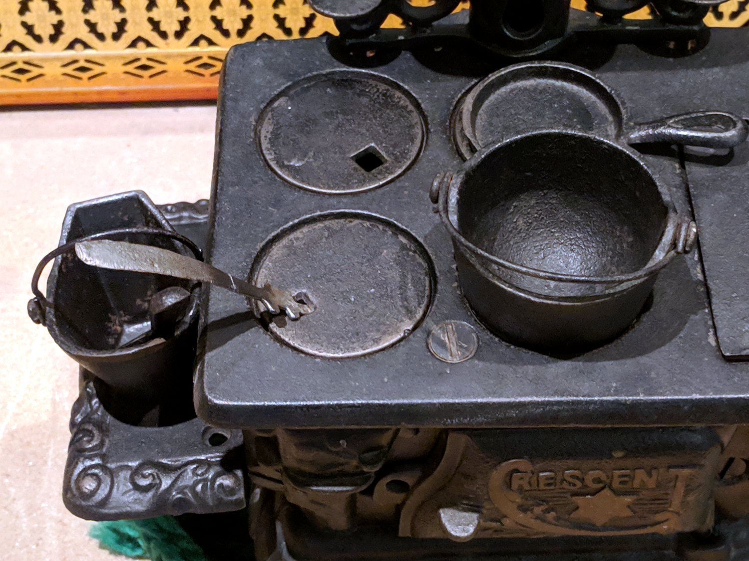
    A cast iron stove (most likely a mid-last-century reproduction rather than a Genuine Antique™) emerged from a living room recess:

    Toy stove with repaired lid lifter
    Toy stove with repaired lid lifter

    The line across the lid lifter handle shows where it broke, long ago, likely while being played with. Back then, I’d done a static-display-grade fix with a dab of clear epoxy, but a better repair seemed called for; my repair-fu has grown stronger.

    I expected the handle to be pot metal, so drilling a hole in both ends for a music-wire stiffener seemed reasonable:

    Toy lid lifter - laser alignment
    Toy lid lifter – laser alignment

    Much to my surprise, the carbide bit skittered off the surface, leaving fine swarf standing on the end. Turns out the lid lifter is cast iron, just like the rest of the stove!

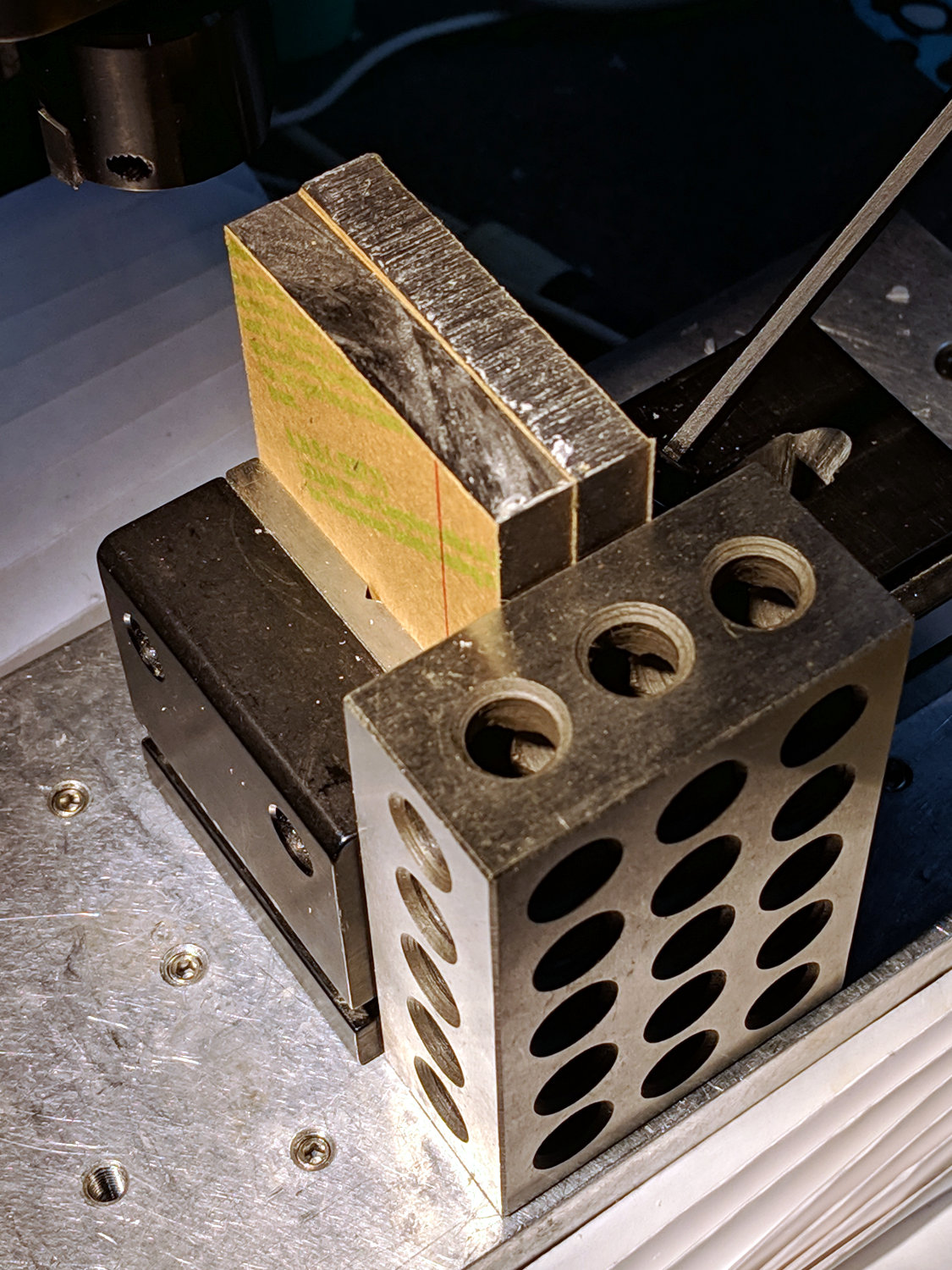
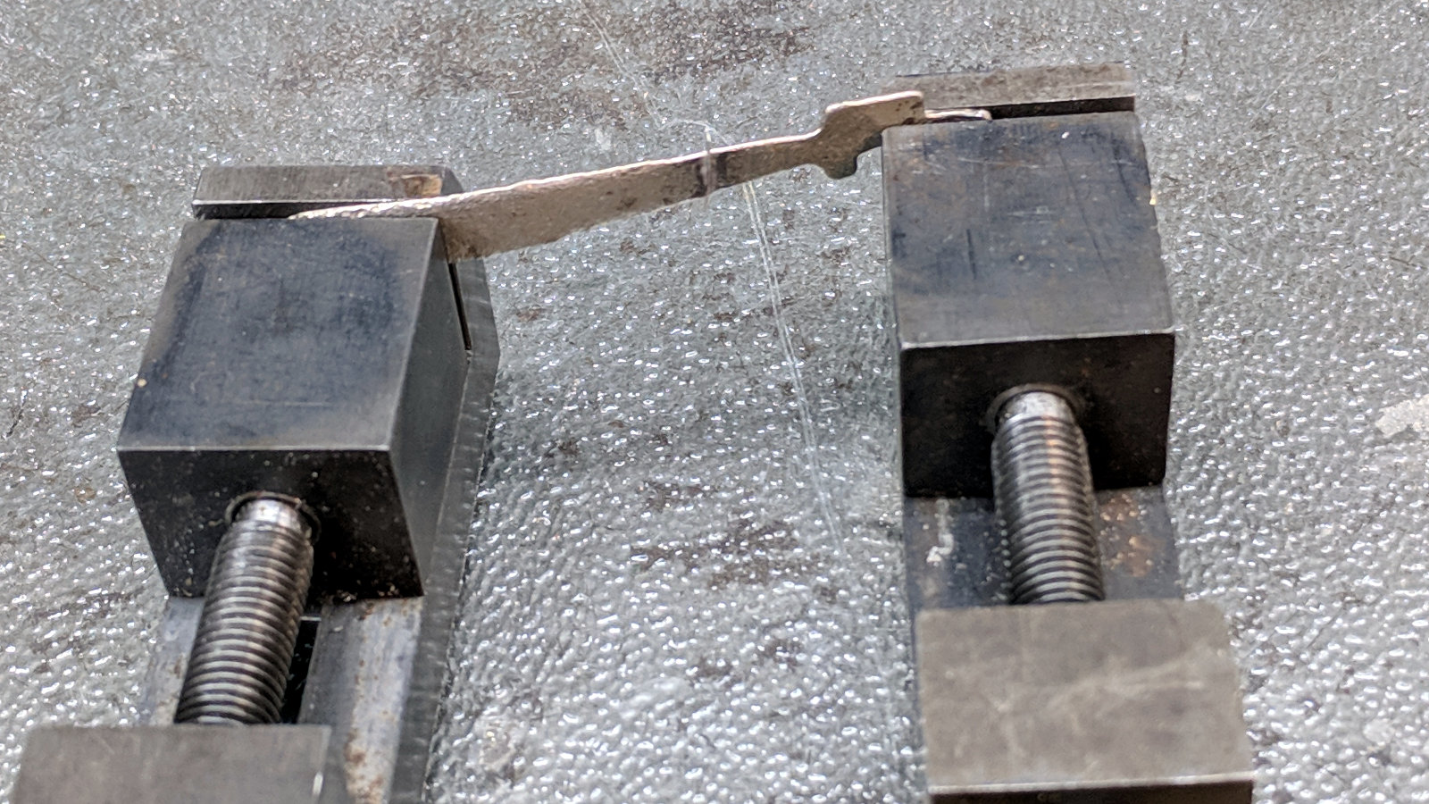
    Given that much of a clue, I aligned the pieces in a pair of machinist’s vises:

    Toy lid lifter - alignment
    Toy lid lifter – alignment

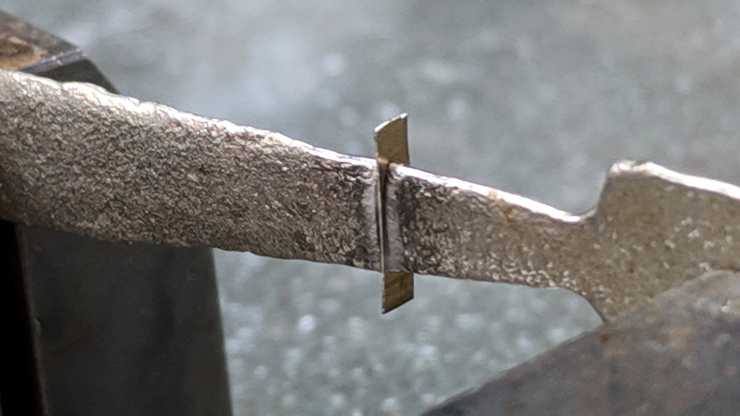
    Slide apart (the vises stand on a smooth glass sheet; the nubbly side is down), dab silver solder flux on the ends, capture a snippet of 40% silver solder in the gap:

    Toy lid lifter - silver solder setup
    Toy lid lifter – silver solder setup

    Hit it ever so gently with a propane torch and slide together:

    Toy lid lifter - silver soldered
    Toy lid lifter – silver soldered

    The solder flows at 1200 °F = 650 °C, roughly corresponding to the blue-gray color near the joint. The nice purple (540 °C) on the left shows where I held the flame to start, with yellows (400 °C) on both sides. Good enough, sez I, it’s going to be a static-display exhibit.

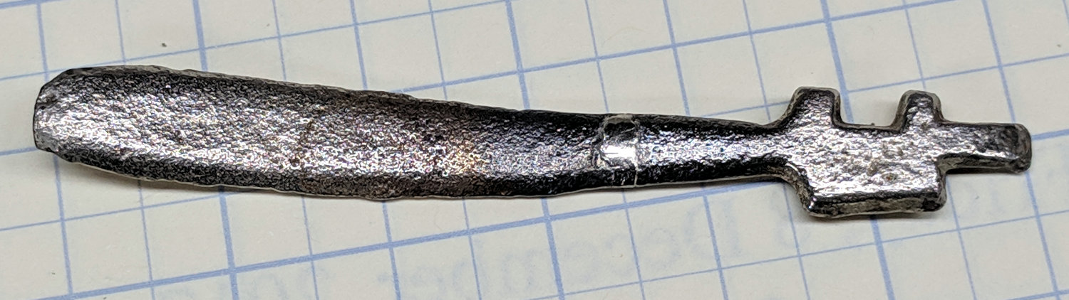
    Most of the solder went to the back side, so I filed it smooth and buffed off most of the heat coloration with a stainless-steel wire wheel in the Dremel:

    Toy lid lifter - bottom
    Toy lid lifter – bottom

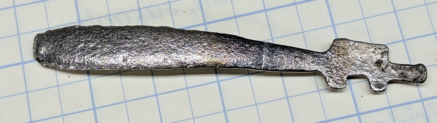
    A little more wire-brush action left the front side looking good:

    Toy lid lifter - top
    Toy lid lifter – top

    As with most of the repairs around here, it simply makes me feel better …

    Now, go play with your toys!

  • Astable Multivibrator: NP-BX1 Base

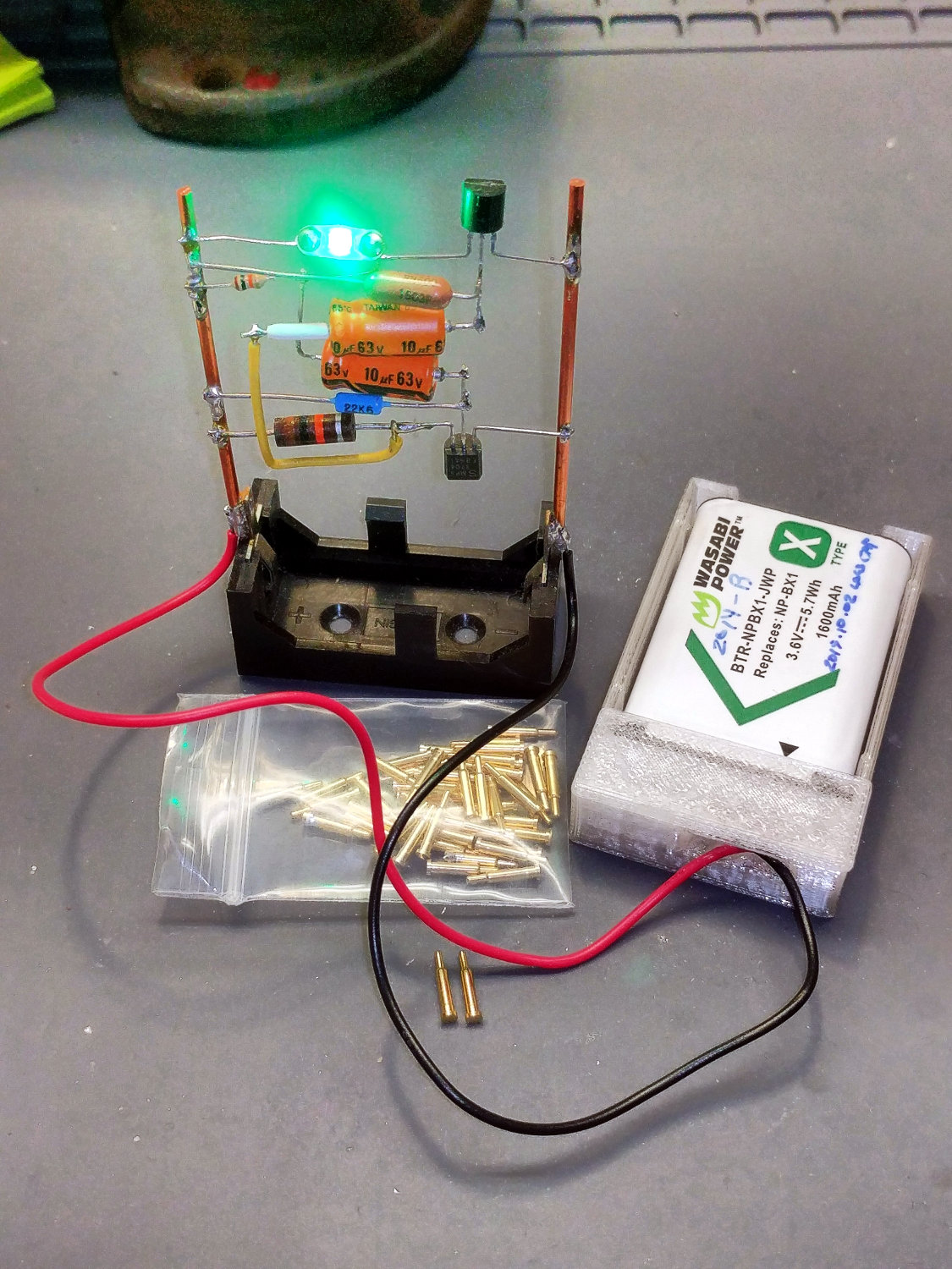
    Adapting the NP-BX1 battery holder to use SMT pogo pins worked well:

    NP-BX1 Holder - SMT pogo pins
    NP-BX1 Holder – SMT pogo pins

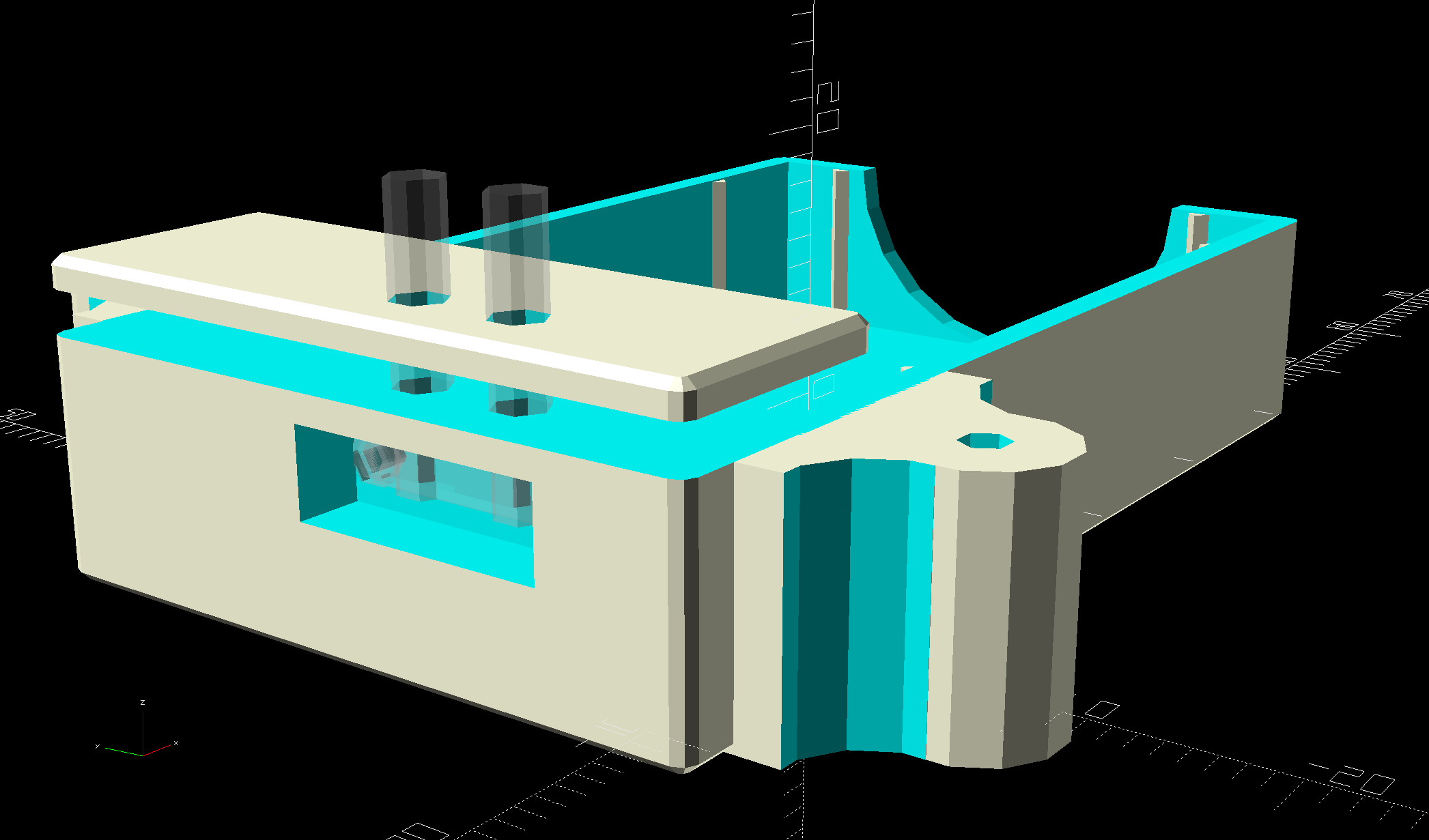
    The next step is to add sockets for those 14 AWG wires:

    NP-BX1 Battery Holder - Wire Posts - solid model
    NP-BX1 Battery Holder – Wire Posts – solid model

    Start by reaming / hand-drilling all the holes to their nominal size and cleaning out the pogo pin pocket.

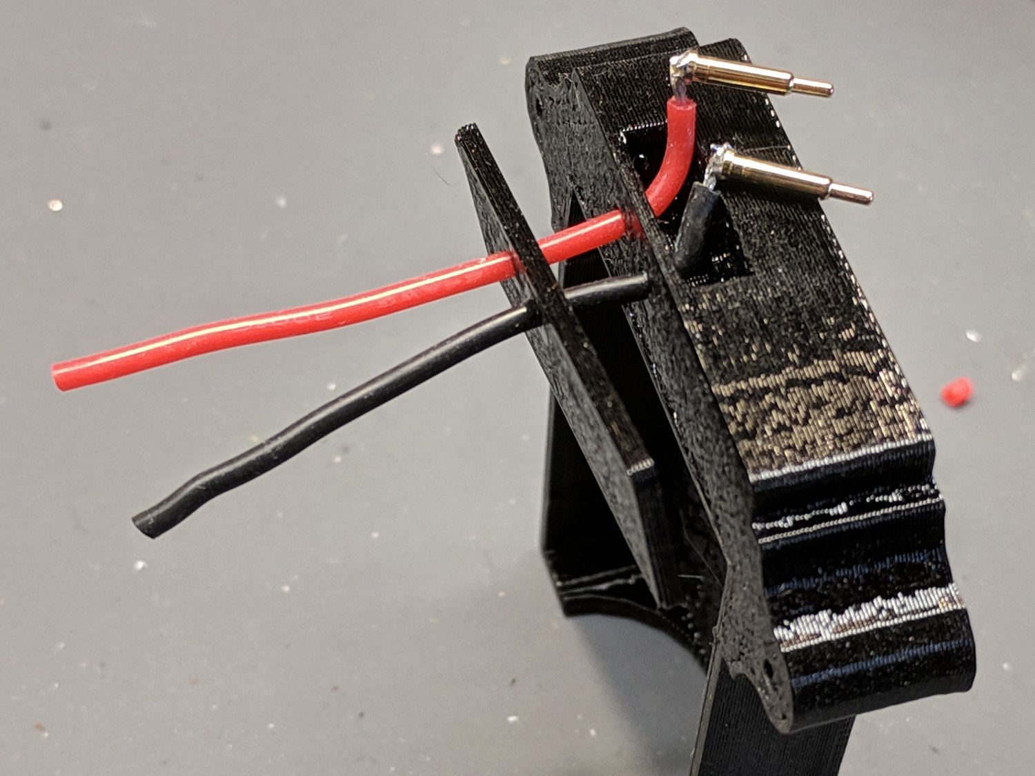
    Solder wires to the pogo pins and thread them through the holder and lid:

    Astable - NP-BX1 holder - pogo pin soldering
    Astable – NP-BX1 holder – pogo pin soldering

    That’s nice, floppy silicone-insulated 24 AWG wire, which may be a bit too thick for this purpose.

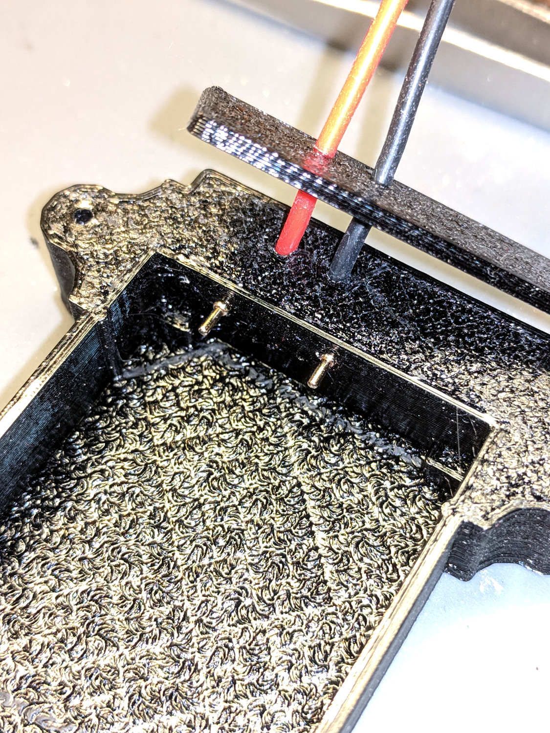
    The pogo pins will, ideally, seat with the end of the body flush at the holder wall. Make it so:

    Astable - NP-BX1 holder - pogo pin protrusion
    Astable – NP-BX1 holder – pogo pin protrusion

    Dress the wires neatly into their pocket:

    Astable - NP-BX1 holder - pogo pin wiring
    Astable – NP-BX1 holder – pogo pin wiring

    Butter the bottom of the lid with epoxy, clamp in place, set it up for curing, then fill the recess:

    Astable - NP-BX1 base - curing
    Astable – NP-BX1 base – curing

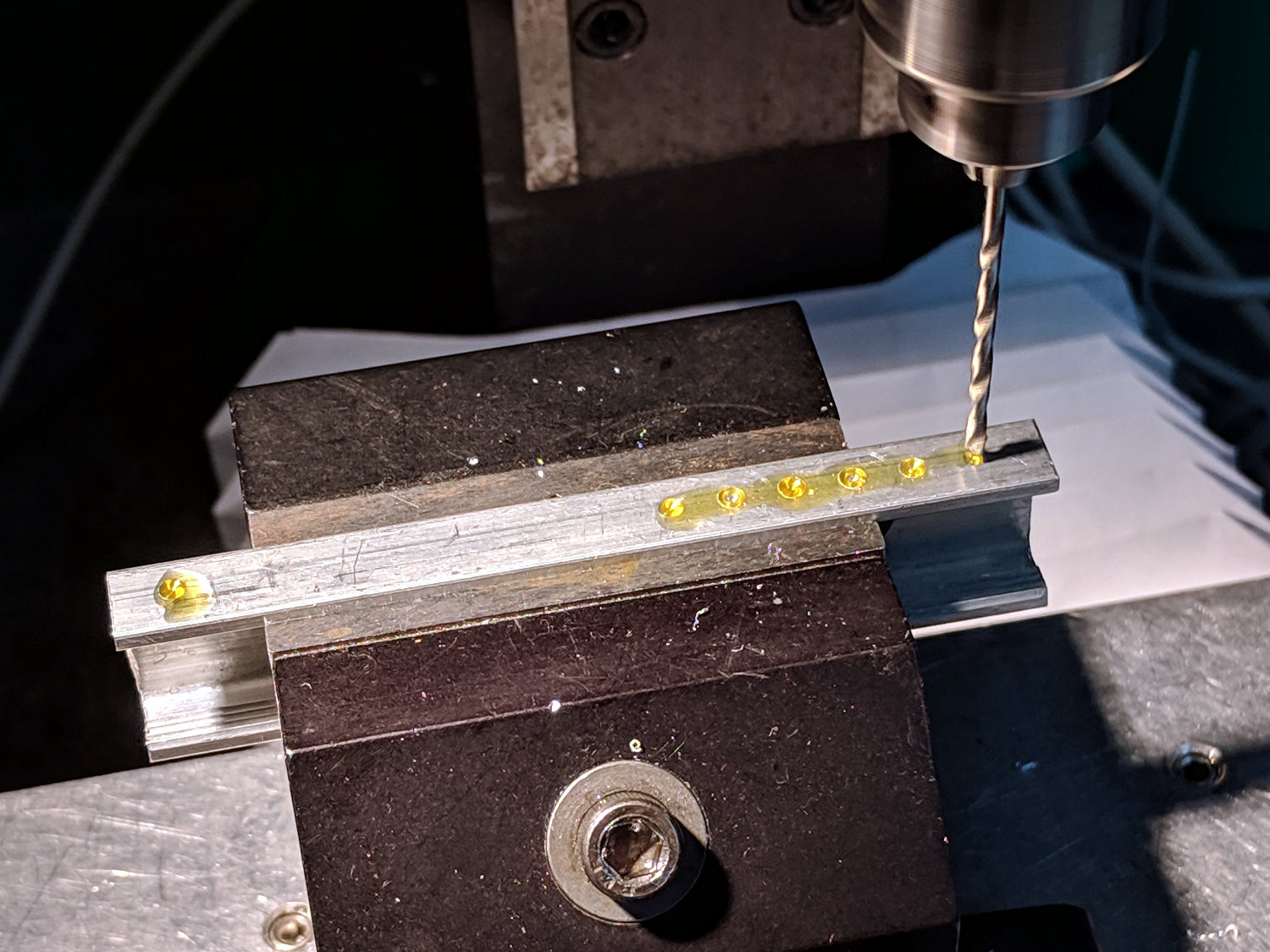
    While it’s curing, make a soldering fixture for the 14 AWG wires:

    Astable - drilling strut soldering fixture
    Astable – drilling strut soldering fixture

    The holes are on 5 mm centers, in the expectation other battery holders will need different spacing.

    Solder it up and stick the wires into the base:

    Astable - NP-BX1 base - detail
    Astable – NP-BX1 base – detail

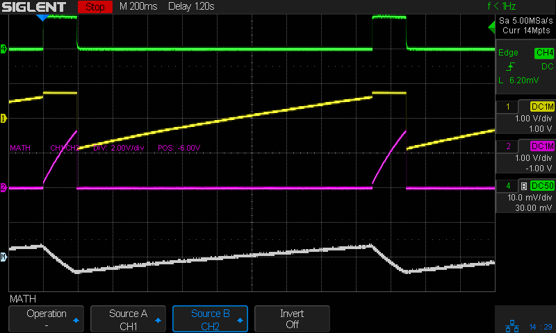
    Jam a battery in and It Just Works™:

    Astable - NP-BX1 3.8V - 20ma-div - cap V
    Astable – NP-BX1 3.8V – 20ma-div – cap V

    The traces:

    • Green = supply current at 20 mA/div
    • Yellow = LED driver transistor base voltage
    • Purple = other transistor collector voltage
    • White = base – collector voltage = capacitor voltage

    The measurement setup was a bit of a hairball:

    Astable - NP-BX1 base - current probe
    Astable – NP-BX1 base – current probe

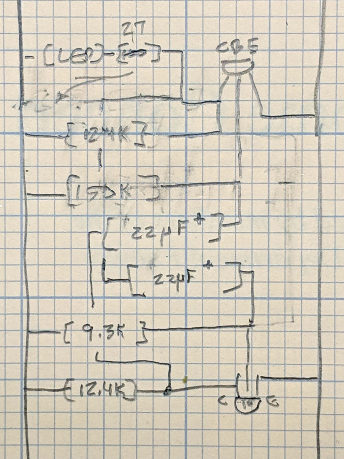
    For completeness, here’s the schematic-and-layout diagram behind the circuitry:

    Astable - NP-BX1 base - schematic
    Astable – NP-BX1 base – schematic

    I love it when a plan comes together!

    The OpenSCAD source code as a GitHub Gist:

    // Holder for Sony NP-BX1 Li-Ion battery
    // Ed Nisley KE4ZNU January 2013
    // 2018-11-15 Adapted for wire leads from 1.5 mm test pins, added upright wire bases
    // Layout options
    Layout = "Fit"; // Show Build Fit Case Lid Pins
    //- Extrusion parameters – must match reality!
    // Print with +2 shells and 3 solid layers
    ThreadThick = 0.25;
    ThreadWidth = 0.35;
    HoleWindage = 0.2;
    function IntegerMultiple(Size,Unit) = Unit * ceil(Size / Unit);
    Protrusion = 0.1; // make holes end cleanly
    inch = 25.4;
    BuildOffset = 3.0; // clearance for build layout
    Gap = 2.0; // separation for Fit parts
    //- Basic dimensions
    WallThick = 4*ThreadWidth; // holder sidewalls
    BaseThick = 6*ThreadThick; // bottom of holder to bottom of battery
    TopThick = 6*ThreadThick; // top of battery to top of holder
    //- Battery dimensions – rationalized from several samples
    // Coordinate origin at battery contact face with key openings below contacts
    Battery = [43.0,30.0,9.5]; // X = length, Y = width, Z = thickness
    Contacts = [[-0.75,6.0,6.2],[-0.75,16.0,6.2]]; // relative to battery edge, front, and bottom
    ContactOC = Contacts[1].y – Contacts[0].y;
    ContactCenter = Contacts[0].y + ContactOC/2;
    KeyBlocks = [[1.75,3.70,2.90],[1.75,3.60,2.90]]; // recesses in battery face set X position
    //- Pin dimensions
    ID = 0;
    OD = 1;
    LENGTH = 2;
    PinShank = [1.5,2.0,6.5]; // shank, flange, compressed length
    PinFlange = [1.5,2.0,0.5]; // flange, length included in PinShank
    PinTip = [0.9,0.9,2.5]; // extended spring-loaded tip
    PinChannel = PinFlange[LENGTH] + 0.5; // cut behind flange for solder overflow
    PinRecess = 3.0; // recess behind pin flange end for epoxy fill
    echo(str("Contact tip dia: ",PinTip[OD]));
    echo(str(" .. shank dia: ",PinShank[ID]));
    OverTravel = 0.5; // space beyond battery face at X origin
    //- Holder dimensions
    GuideRadius = ThreadWidth; // friction fit ridges
    GuideOffset = 7; // from compartment corners
    ThumbRadius = 10.0; // thumb opening at end of battery
    CornerRadius = 3*ThreadThick; // nice corner rounding
    CaseSize = [Battery.x + PinShank[LENGTH] + OverTravel + PinRecess + GuideRadius + WallThick,
    Battery.y + 2*WallThick + 2*GuideRadius,
    Battery.z + BaseThick + TopThick];
    CaseOffset = [-(PinShank[LENGTH] + OverTravel + PinRecess),-(WallThick + GuideRadius),0]; // position around battery
    LidOverhang = 2.0; // over top of battery for retention
    LidSize = [-CaseOffset.x + LidOverhang,CaseSize.y,TopThick];
    LidOffset = [0.0,CaseOffset.y,0];
    //- Wire struts
    StrutDia = 1.6; // AWG 14 = 1.6 mm
    StrutOC = 45;
    StrutSides = 3*4;
    StrutBase = [StrutDia,StrutDia + 4*WallThick,CaseSize.z – TopThick]; // ID = wire, OD=buildable
    //———————-
    // Useful routines
    module PolyCyl(Dia,Height,ForceSides=0) { // based on nophead's polyholes
    Sides = (ForceSides != 0) ? ForceSides : (ceil(Dia) + 2);
    FixDia = Dia / cos(180/Sides);
    cylinder(r=(FixDia + HoleWindage)/2,h=Height,$fn=Sides);
    }
    //——————-
    //– Guides for tighter friction fit
    module Guides() {
    translate([GuideOffset,-GuideRadius,0])
    PolyCyl(2*GuideRadius,(Battery.z – Protrusion),4);
    translate([GuideOffset,(Battery.y + GuideRadius),0])
    PolyCyl(2*GuideRadius,(Battery.z – Protrusion),4);
    translate([(Battery.x – GuideOffset),-GuideRadius,0])
    PolyCyl(2*GuideRadius,(Battery.z – Protrusion),4);
    translate([(Battery.x – GuideOffset),(Battery.y + GuideRadius),0])
    PolyCyl(2*GuideRadius,(Battery.z – Protrusion),4);
    translate([(Battery.x + GuideRadius),GuideOffset/2,0])
    PolyCyl(2*GuideRadius,(Battery.z – Protrusion),4);
    translate([(Battery.x + GuideRadius),(Battery.y – GuideOffset/2),0])
    PolyCyl(2*GuideRadius,(Battery.z – Protrusion),4);
    }
    //– Contact pins
    // Rotated to put them in their natural oriention
    // Aligned to put tip base / end of shank at Overtravel limit
    module PinShape() {
    translate([-(PinShank[LENGTH] + OverTravel),0,0])
    rotate([0,90,0])
    rotate(180/6)
    union() {
    PolyCyl(PinTip[OD],PinShank[LENGTH] + PinTip[LENGTH],6);
    PolyCyl(PinShank[ID],PinShank[LENGTH] + Protrusion,6); // slight extension for clean cuts
    PolyCyl(PinFlange[OD],PinFlange[LENGTH],6);
    }
    }
    // Position pins to put end of shank at battery face
    // Does not include recess access into case
    module PinAssembly() {
    union() {
    for (p = Contacts)
    translate([0,p.y,p.z])
    PinShape();
    translate([-(PinShank[LENGTH] + OverTravel) + PinChannel/2, // solder space
    ContactCenter,
    Contacts[0].z])
    cube([PinChannel,(Contacts[1].y – Contacts[0].y),PinFlange[OD]],center=true);
    for (j=[-1,1]) // wire channels
    translate([-(PinShank[LENGTH] + OverTravel – PinChannel/2),
    j*ContactOC/4 + ContactCenter,
    Contacts[0].z – PinFlange[OD]/2])
    rotate(180/6)
    PolyCyl(PinFlange[OD],CaseSize.z,6);
    }
    }
    //– Case with origin at battery corner
    module Case() {
    difference() {
    union() {
    difference() {
    union() {
    translate([(CaseSize.x/2 + CaseOffset.x), // basic case shape
    (CaseSize.y/2 + CaseOffset.y),
    (CaseSize.z/2 – BaseThick)])
    hull()
    for (i=[-1,1], j=[-1,1], k=[-1,1])
    translate([i*(CaseSize.x/2 – CornerRadius),
    j*(CaseSize.y/2 – CornerRadius),
    k*(CaseSize.z/2 – CornerRadius)])
    sphere(r=CornerRadius/cos(180/8),$fn=8); // cos() fixes undersize spheres!
    hull() // wire strut bases
    for (j=[-1,1])
    translate([0,j*StrutOC/2 + Battery.y/2,-BaseThick])
    rotate(180/StrutSides)
    cylinder(d=StrutBase[OD],h=StrutBase[LENGTH],$fn=StrutSides);
    translate([0,Battery.y/2,StrutBase[LENGTH]/2 – BaseThick])
    cube([2*StrutBase[OD],StrutOC,StrutBase[LENGTH]],center=true);
    }
    translate([-OverTravel,-GuideRadius,0])
    cube([(Battery.x + GuideRadius + OverTravel),
    (Battery.y + 2*GuideRadius),
    (Battery.z + Protrusion)]); // battery space
    }
    Guides(); // improve friction fit
    translate([-OverTravel,-GuideRadius,0]) // battery keying blocks
    cube(KeyBlocks[0] + [OverTravel,GuideRadius,0],center=false);
    translate([-OverTravel,(Battery.y – KeyBlocks[1].y),0])
    cube(KeyBlocks[1] + [OverTravel,GuideRadius,0],center=false);
    }
    translate([2*CaseOffset.x, // battery top access
    (CaseOffset.y – Protrusion),
    Battery.z])
    cube([2*CaseSize.x,(CaseSize.y + 2*Protrusion),(TopThick + Protrusion)]);
    if (false)
    translate([(CaseOffset.x – Protrusion), // battery insertion allowance
    (CaseOffset.y – Protrusion),
    Battery.z])
    cube([(CaseSize.x + 2*Protrusion),(CaseSize.y + 2*Protrusion),(TopThick + Protrusion)]);
    for (j=[-1,1]) // strut wires
    translate([0,j*StrutOC/2 + Battery.y/2,-(BaseThick + Protrusion)])
    PolyCyl(StrutBase[ID],StrutBase[LENGTH] + 2*Protrusion,6);
    for (i=[-1,1], j=[-1,1])
    translate([i*StrutBase[OD],j*StrutOC/2 + Battery.y/2,-(BaseThick + Protrusion)])
    rotate(180/StrutSides)
    PolyCyl(StrutBase[OD],StrutBase[LENGTH] + 2*Protrusion,StrutSides);
    translate([(Battery.x – Protrusion), // remove thumb notch
    (CaseSize.y/2 + CaseOffset.y),
    (ThumbRadius)])
    rotate([90,0,0])
    rotate([0,90,0])
    cylinder(r=ThumbRadius,
    h=(WallThick + GuideRadius + 2*Protrusion),
    $fn=22);
    PinAssembly();
    translate([CaseOffset.x + PinRecess + Protrusion,(Contacts[1].y + Contacts[0].y)/2,Contacts[0].z])
    translate([-PinRecess,0,0])
    cube([2*PinRecess,
    (Contacts[1].y – Contacts[0].y + PinFlange[OD]),
    2*PinFlange[OD]],center=true);
    }
    }
    // Lid position offset to match case
    module Lid() {
    difference() {
    translate([-LidSize.x/2 + LidOffset.x + LidOverhang,LidSize.y/2 + LidOffset.y,0])
    difference() {
    hull()
    for (i=[-1,1], j=[-1,1], k=[-1,1])
    translate([i*(LidSize.x/2 – CornerRadius),
    j*(LidSize.y/2 – CornerRadius),
    k*(LidSize.z – CornerRadius)]) // double thickness for flat bottom
    sphere(r=CornerRadius,$fn=8);
    translate([0,0,-LidSize.z/2]) // remove bottom
    cube([(LidSize.x + 2*Protrusion),(LidSize.y + 2*Protrusion),LidSize.z],center=true);
    translate([LidSize.x/8,0,0])
    cube([LidSize.x/4,0.75*LidSize.y,4*ThreadThick],center=true); // epoxy recess
    }
    translate([0,0,-(Contacts[0].z + PinFlange[OD])]) // punch wire holes
    PinAssembly();
    }
    }
    //——————-
    // Build it!
    if (Layout == "Case")
    Case();
    if (Layout == "Lid")
    Lid();
    if (Layout == "Pins") {
    color("Silver",0.5)
    PinShape();
    PinAssembly();
    }
    if (Layout == "Show") { // reveal pin assembly
    difference() {
    Case();
    translate([(CaseOffset.x – Protrusion),
    Contacts[1].y,
    Contacts[1].z])
    cube([(-CaseOffset.x + Protrusion),
    CaseSize.y,
    (CaseSize.z – Contacts[0].z + Protrusion)]);
    translate([(CaseOffset.x – Protrusion),
    (CaseOffset.y – Protrusion),
    0])
    cube([(-CaseOffset.x + Protrusion),
    Contacts[0].y + Protrusion – CaseOffset.y,
    CaseSize.z]);
    }
    translate([0,0,Battery.z + Gap])
    Lid();
    color("Silver",0.15)
    PinAssembly();
    }
    if (Layout == "Build") {
    translate([-(CaseSize.x/2 + CaseOffset.x),-(CaseOffset.y – BuildOffset),BaseThick])
    Case();
    translate([CaseSize.x/2,-LidSize.x/2,0])
    rotate(90)
    Lid();
    }
    if (Layout == "Fit") {
    Case();
    translate([0,0,(Battery.z + Gap)])
    Lid();
    color("Silver",0.25)
    PinAssembly();
    }
  • Vacuum Tube LEDs: 21HB5A on a Guilloche Platter

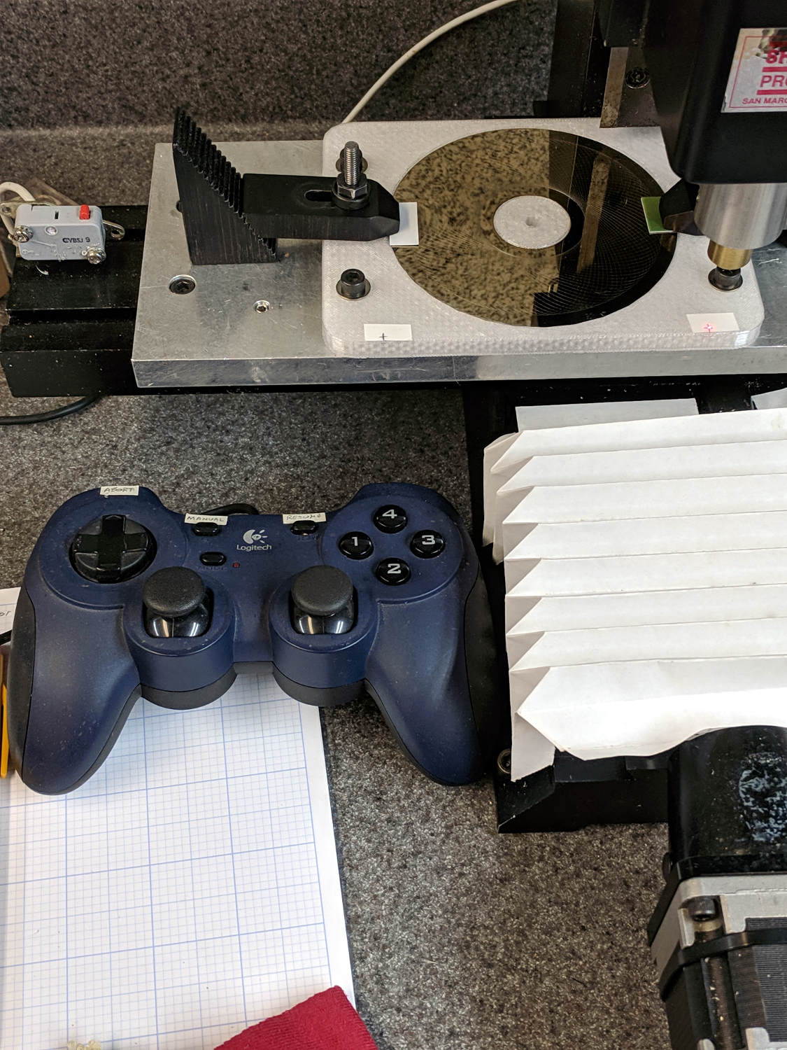
    With the Joggy Thing running in LinuxCNC 2.7, touching XY off on the fixture was trivially easy:

    LinuxCNC - Sherline Mill - Logitech Gamepad
    LinuxCNC – Sherline Mill – Logitech Gamepad

    The pips are 100 mm apart at (-50,-50) and (+50,50). Astonishingly, the laser aligner batteries are in fine shape.

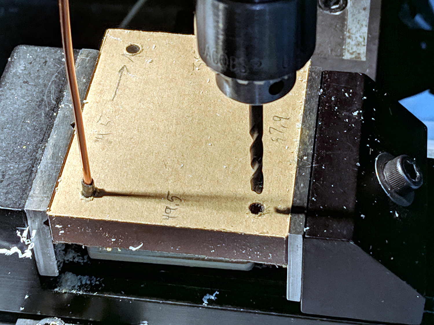
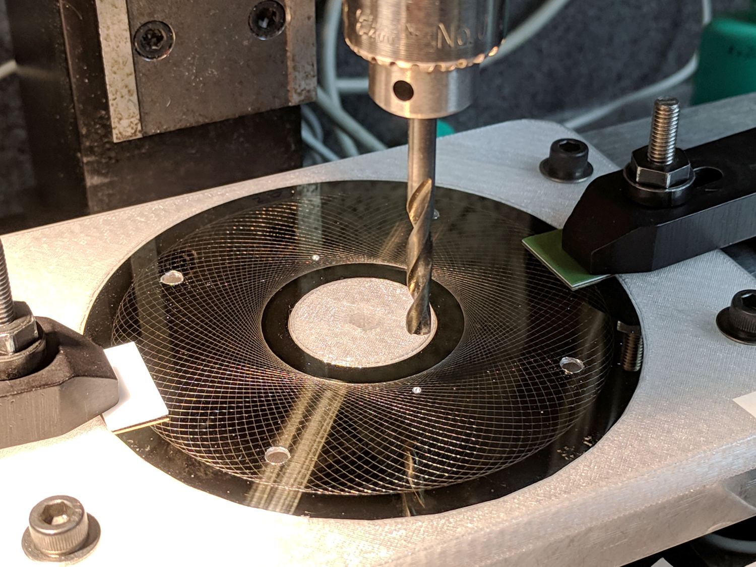
    I should have protected the platter before drilling all those holes:

    Guilloche platter - drilling
    Guilloche platter – drilling

    All’s well that ends well:

    21HB5A - Guilloche platter
    21HB5A – Guilloche platter

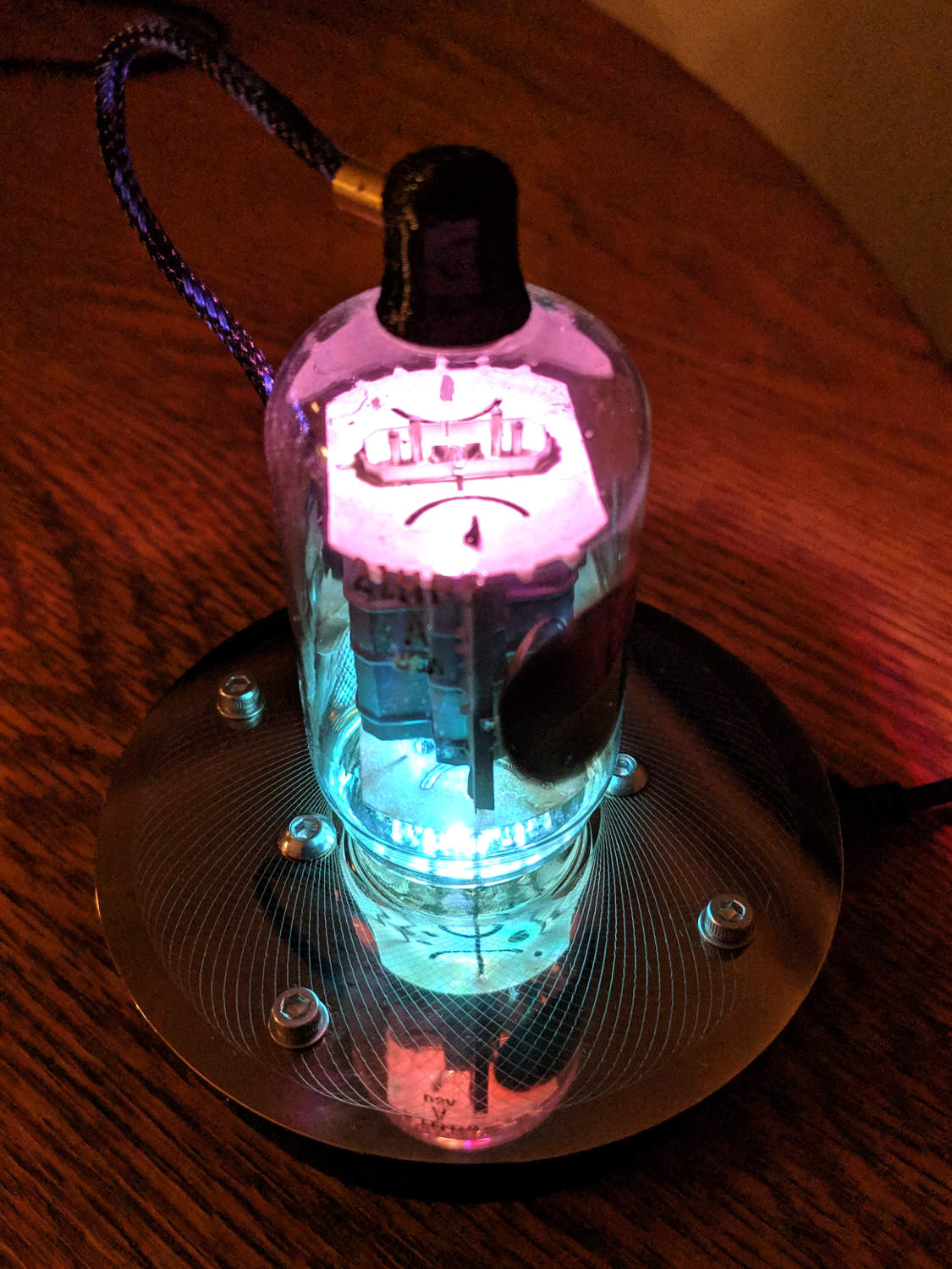
    It looks even better in the dark, although you’d never know it from this picture:

    21HB5A - Guilloche platter - dark
    21HB5A – Guilloche platter – dark

    I wish I could engrave those patterns on already-drilled platters, but dragging a diamond point into a hole can’t possibly end well. I could deploy the Tiny Sandblaster with a vinyl mask, if I had enough artistic eptitude to lay out a good-looking mask.

  • LinuxCNC 2.7 vs. Logitech Joggy Thing

    The old Atom running LinuxCNC for the Sherline finally stopped booting, so I popped the Optiplex 760 off the stack and did a live-USB trial run. The latency / jitter worked out around 25 µs, slightly worse than before, but still Good Enough, and the StepConf utility coerced the motors into working OK.

    What didn’t work was the old Eagle-to-HAL code defining the Logitch Gamepad as a Joggy Thing to allow smooth joystick jog control. Well, stuff changes over the course of eight years, but, in this case, the fix turned out to be a one-liner: the probe_parport module isn’t needed nowadays.

    With that out of the way, it runs fine:

    LinuxCNC - Sherline Mill - Logitech Gamepad
    LinuxCNC – Sherline Mill – Logitech Gamepad

    The INI and HAL files defining the Sherline configuration as a GitHub Gist:

    # HAL config file automatically generated by Eagle-CAD ULP:
    # [/mnt/bulkdata/Project Files/eagle/ulp/hal-write-2.5.ulp]
    # (C) Martin Schoeneck.de 2008
    # Charalampos Alexopoulos 2011
    # Mods Ed Nisley KE4ZNU 2010 2013
    # Path [/mnt/bulkdata/Project Files/eagle/projects/LinuxCNC for M2/]
    # ProjectName [LinuxCNC Sherline Configuration]
    # File name [/mnt/bulkdata/Project Files/eagle/projects/LinuxCNC for M2/LinuxCNC Sherline Configuration.hal]
    # Created [11:17:21 17-Feb-2013]
    ####################################################
    # Load realtime and userspace modules
    loadrt trivkins
    loadrt [EMCMOT]EMCMOT key=[EMCMOT]SHMEM_KEY num_joints=[TRAJ]AXES base_period_nsec=[EMCMOT]BASE_PERIOD servo_period_nsec=[EMCMOT]SERVO_PERIOD traj_period_nsec=[EMCMOT]SERVO_PERIOD
    # not needed in 2.7
    # loadrt probe_parport
    loadrt hal_parport cfg="[PARPORT]ADDRESS out"
    loadrt stepgen step_type=0,0,0,0
    loadrt pwmgen output_type=0
    loadusr -W hal_manualtoolchange
    loadusr -W hal_input -KA Dual
    loadrt logic count=1 personality=0x104
    loadrt constant count=13
    loadrt and2 count=17
    loadrt conv_float_s32 count=1
    loadrt flipflop count=4
    loadrt mux2 count=5
    loadrt mux4 count=1
    loadrt not count=8
    loadrt or2 count=14
    loadrt scale count=7
    loadrt timedelay count=1
    loadrt toggle count=1
    ####################################################
    # Hook functions into threads
    addf stepgen.make-pulses base-thread
    addf pwmgen.make-pulses base-thread
    addf parport.0.read base-thread
    addf parport.0.write base-thread
    addf parport.0.reset base-thread
    addf logic.0 base-thread
    addf motion-command-handler servo-thread
    addf motion-controller servo-thread
    addf stepgen.update-freq servo-thread
    addf stepgen.capture-position servo-thread
    addf pwmgen.update servo-thread
    addf constant.0 servo-thread
    addf constant.1 servo-thread
    addf constant.2 servo-thread
    addf constant.3 servo-thread
    addf constant.4 servo-thread
    addf constant.5 servo-thread
    addf constant.6 servo-thread
    addf constant.7 servo-thread
    addf constant.8 servo-thread
    addf constant.9 servo-thread
    addf constant.10 servo-thread
    addf constant.11 servo-thread
    addf constant.12 servo-thread
    addf and2.0 servo-thread
    addf and2.1 servo-thread
    addf and2.2 servo-thread
    addf and2.3 servo-thread
    addf and2.4 servo-thread
    addf and2.5 servo-thread
    addf and2.6 servo-thread
    addf and2.7 servo-thread
    addf and2.8 servo-thread
    addf and2.9 servo-thread
    addf and2.10 servo-thread
    addf and2.11 servo-thread
    addf and2.12 servo-thread
    addf and2.13 servo-thread
    addf and2.14 servo-thread
    addf and2.15 servo-thread
    addf and2.16 servo-thread
    addf conv-float-s32.0 servo-thread
    addf toggle.0 servo-thread
    addf flipflop.0 servo-thread
    addf flipflop.1 servo-thread
    addf flipflop.2 servo-thread
    addf flipflop.3 servo-thread
    addf timedelay.0 servo-thread
    addf or2.0 servo-thread
    addf or2.1 servo-thread
    addf or2.2 servo-thread
    addf or2.3 servo-thread
    addf or2.4 servo-thread
    addf or2.5 servo-thread
    addf or2.6 servo-thread
    addf or2.7 servo-thread
    addf or2.8 servo-thread
    addf or2.9 servo-thread
    addf or2.10 servo-thread
    addf or2.11 servo-thread
    addf or2.12 servo-thread
    addf or2.13 servo-thread
    addf not.0 servo-thread
    addf not.1 servo-thread
    addf not.2 servo-thread
    addf not.3 servo-thread
    addf not.4 servo-thread
    addf not.5 servo-thread
    addf not.6 servo-thread
    addf not.7 servo-thread
    addf scale.0 servo-thread
    addf scale.1 servo-thread
    addf scale.2 servo-thread
    addf scale.3 servo-thread
    addf scale.4 servo-thread
    addf scale.5 servo-thread
    addf scale.6 servo-thread
    addf mux2.0 servo-thread
    addf mux4.0 servo-thread
    addf mux2.1 servo-thread
    addf mux2.2 servo-thread
    addf mux2.3 servo-thread
    addf mux2.4 servo-thread
    ####################################################
    # Set parameters
    setp parport.0.reset-time [PARPORT]RESET_TIME
    setp stepgen.0.maxaccel [AXIS_0]STEPGEN_MAXACCEL
    setp stepgen.0.maxvel [AXIS_0]MAX_VELOCITY
    setp stepgen.0.dirhold [PARPORT]DIRHOLD
    setp stepgen.0.dirsetup [PARPORT]DIRSETUP
    setp stepgen.0.steplen [PARPORT]STEPLEN
    setp stepgen.0.stepspace [PARPORT]STEPSPACE
    setp stepgen.0.position-scale [AXIS_0]SCALE
    setp parport.0.pin-03-out-reset FALSE
    setp parport.0.pin-05-out-reset FALSE
    setp parport.0.pin-07-out-reset FALSE
    setp parport.0.pin-09-out-reset FALSE
    setp parport.0.pin-17-out-reset FALSE
    setp stepgen.1.maxaccel [AXIS_1]STEPGEN_MAXACCEL
    setp stepgen.1.maxvel [AXIS_1]MAX_VELOCITY
    setp stepgen.1.dirhold [PARPORT]DIRHOLD
    setp stepgen.1.dirsetup [PARPORT]DIRSETUP
    setp stepgen.1.steplen [PARPORT]STEPLEN
    setp stepgen.1.stepspace [PARPORT]STEPSPACE
    setp stepgen.1.position-scale [AXIS_1]SCALE
    setp stepgen.2.maxaccel [AXIS_2]STEPGEN_MAXACCEL
    setp stepgen.2.maxvel [AXIS_2]MAX_VELOCITY
    setp stepgen.2.dirhold [PARPORT]DIRHOLD
    setp stepgen.2.dirsetup [PARPORT]DIRSETUP
    setp stepgen.2.steplen [PARPORT]STEPLEN
    setp stepgen.2.stepspace [PARPORT]STEPSPACE
    setp stepgen.2.position-scale [AXIS_2]SCALE
    setp stepgen.3.maxaccel [AXIS_3]STEPGEN_MAXACCEL
    setp stepgen.3.maxvel [AXIS_3]MAX_VELOCITY
    setp stepgen.3.dirhold [PARPORT]DIRHOLD
    setp stepgen.3.dirsetup [PARPORT]DIRSETUP
    setp stepgen.3.steplen [PARPORT]STEPLEN
    setp stepgen.3.stepspace [PARPORT]STEPSPACE
    setp stepgen.3.position-scale [AXIS_3]SCALE
    setp parport.0.pin-04-out-invert TRUE
    setp parport.0.pin-06-out-invert TRUE
    ####################################################
    # Set constants
    setp constant.0.value 0.1
    setp constant.1.value 20
    setp constant.2.value [TRAJ]MAX_LINEAR_VELOCITY
    setp constant.3.value [TRAJ]MAX_ANGULAR_VELOCITY
    setp constant.4.value 60
    setp constant.5.value 0.50
    setp constant.6.value 1.00
    setp constant.7.value 0.10
    setp constant.8.value 0.10
    setp constant.9.value 0.0
    setp constant.10.value -1.0
    setp constant.11.value 0.020
    setp constant.12.value 0.000
    ####################################################
    # Connect Modules with nets
    net a-amp-enable logic.0.in-03 axis.3.amp-enable-out stepgen.3.enable
    net a-analog halui.jog.3.analog mux2.4.out
    net a-button-minus or2.0.in0 input.0.btn-joystick and2.7.in0
    net a-button-plus or2.0.in1 input.0.btn-thumb2 and2.8.in0
    net a-buttons-active or2.0.out or2.1.in0 or2.11.in1
    net a-direction parport.0.pin-08-out stepgen.3.dir
    net a-disable not.7.out and2.13.in1
    net a-enable or2.11.in0 flipflop.3.out not.7.in mux2.4.sel
    net a-jog input.0.abs-z-position mux2.4.in1
    net a-knob-active or2.9.out not.2.in and2.15.in1
    net a-knob-inactive not.2.out and2.14.in1
    net a-select and2.16.in0 and2.15.out
    net a-set flipflop.3.set and2.16.out
    net a-step parport.0.pin-09-out stepgen.3.step
    net all-amps-enabled logic.0.and parport.0.pin-17-out
    net angular_motion or2.11.out mux2.0.sel
    net any-buttons-active mux4.0.sel0 or2.12.out
    net axis-disabled-value constant.9.out mux2.1.in0 mux2.2.in0 mux2.3.in0 mux2.4.in0
    net az-buttons-active or2.1.out or2.12.in1 or2.13.in0
    net az-reset flipflop.2.reset and2.14.out flipflop.3.reset
    net button-crawl scale.4.out mux4.0.in3
    net button-fast scale.2.out mux4.0.in1 scale.4.in
    net estop-a and2.0.in0 input.0.btn-top2
    net estop-b and2.0.in1 input.0.btn-base
    net estop-out parport.0.pin-01-out iocontrol.0.emc-enable-in iocontrol.0.user-enable-out
    net homeswitches parport.0.pin-10-in-not axis.0.home-sw-in axis.1.home-sw-in axis.2.home-sw-in axis.3.home-sw-in
    net jog-crawl toggle.0.out mux4.0.sel1
    net jog-speed halui.jog-speed mux4.0.out
    net knob-crawl mux4.0.in2 scale.3.out
    net knob-fast mux4.0.in0 scale.1.out scale.3.in
    net manual-mode halui.mode.manual input.0.btn-base3
    net n_9 axis.0.motor-pos-cmd stepgen.0.position-cmd
    net n_11 axis.0.motor-pos-fb stepgen.0.position-fb
    net n_13 and2.0.out halui.estop.activate
    net n_14 or2.3.in0 input.0.btn-base5
    net n_15 or2.3.in1 input.0.btn-base6
    net n_16 toggle.0.in or2.3.out
    net n_17 conv-float-s32.0.out input.0.abs-x-flat input.0.abs-y-flat input.0.abs-z-flat input.0.abs-rz-flat
    net n_18 constant.1.out conv-float-s32.0.in
    net n_19 constant.4.out scale.0.gain
    net n_20 constant.5.out scale.1.gain
    net n_21 constant.6.out scale.2.gain
    net n_22 constant.7.out scale.3.gain
    net n_23 scale.4.gain constant.8.out
    net n_24 constant.0.out halui.jog-deadband
    net n_25 constant.2.out mux2.0.in0
    net n_26 mux2.0.in1 constant.3.out
    net n_34 axis.1.motor-pos-cmd stepgen.1.position-cmd
    net n_36 axis.1.motor-pos-fb stepgen.1.position-fb
    net n_42 or2.7.in0 input.0.abs-x-is-pos
    net n_43 or2.7.in1 input.0.abs-x-is-neg
    net n_44 or2.8.in0 input.0.abs-y-is-pos
    net n_45 or2.8.in1 input.0.abs-y-is-neg
    net n_46 or2.9.in0 input.0.abs-z-is-pos
    net n_47 or2.9.in1 input.0.abs-z-is-neg
    net n_48 or2.10.in0 input.0.abs-rz-is-pos
    net n_49 or2.10.in1 input.0.abs-rz-is-neg
    net n_51 constant.10.out scale.5.gain scale.6.gain
    net n_54 constant.11.out timedelay.0.on-delay
    net n_55 constant.12.out timedelay.0.off-delay
    net n_56 timedelay.0.out and2.1.in1 and2.2.in1 and2.4.in1 and2.3.in1 and2.5.in1 and2.6.in1 and2.8.in1 and2.7.in1
    net n_57 and2.1.out halui.jog.0.minus
    net n_58 and2.2.out halui.jog.0.plus
    net n_59 and2.3.out halui.jog.1.minus
    net n_60 halui.jog.1.plus and2.4.out
    net n_61 and2.5.out halui.jog.2.minus
    net n_62 and2.6.out halui.jog.2.plus
    net n_63 and2.7.out halui.jog.3.minus
    net n_64 and2.8.out halui.jog.3.plus
    net n_67 axis.2.motor-pos-cmd stepgen.2.position-cmd
    net n_69 axis.2.motor-pos-fb stepgen.2.position-fb
    net n_77 axis.3.motor-pos-cmd stepgen.3.position-cmd
    net n_79 axis.3.motor-pos-fb stepgen.3.position-fb
    net probe-in parport.0.pin-15-in-not motion.probe-input
    net program-resume halui.program.resume input.0.btn-base4
    net reset-estop input.0.btn-base2 halui.estop.reset
    net tool-change iocontrol.0.tool-change hal_manualtoolchange.change
    net tool-changed hal_manualtoolchange.changed iocontrol.0.tool-changed
    net tool-number iocontrol.0.tool-prep-number hal_manualtoolchange.number
    net tool-prepare-loopback iocontrol.0.tool-prepare iocontrol.0.tool-prepared
    net vel-per-minute scale.0.out scale.1.in scale.2.in
    net vel-per-second mux2.0.out scale.0.in
    net x-amp-enable logic.0.in-00 axis.0.amp-enable-out stepgen.0.enable
    net x-analog mux2.1.out halui.jog.0.analog
    net x-buttons-active or2.5.in0 or2.4.out
    net x-direction parport.0.pin-02-out stepgen.0.dir
    net x-disable not.4.out and2.12.in1
    net x-enable not.4.in flipflop.0.out mux2.1.sel
    net x-hat-minus or2.4.in1 input.0.abs-hat0x-is-neg and2.1.in0
    net x-hat-plus or2.4.in0 input.0.abs-hat0x-is-pos and2.2.in0
    net x-jog input.0.abs-x-position mux2.1.in1
    net x-knob-active or2.7.out not.0.in and2.9.in0
    net x-knob-inactive not.0.out and2.10.in0 and2.11.in0
    net x-set and2.9.out flipflop.0.set
    net x-step parport.0.pin-03-out stepgen.0.step
    net xy-buttons-active or2.5.out or2.12.in0 or2.13.in1
    net xy-reset flipflop.0.reset and2.10.out flipflop.1.reset
    net xyza-buttons-active or2.13.out timedelay.0.in
    net y-amp-enable logic.0.in-01 axis.1.amp-enable-out stepgen.1.enable
    net y-analog halui.jog.1.analog mux2.2.out
    net y-buttons-active or2.6.out or2.5.in1
    net y-direction parport.0.pin-04-out stepgen.1.dir
    net y-disable not.5.out and2.9.in1
    net y-enable flipflop.1.out not.5.in mux2.2.sel
    net y-hat-minus or2.6.in1 input.0.abs-hat0y-is-neg and2.4.in0
    net y-hat-plus or2.6.in0 input.0.abs-hat0y-is-pos and2.3.in0
    net y-jog input.0.abs-y-position scale.5.in
    net y-jog-reversed mux2.2.in1 scale.5.out
    net y-knob-active not.1.in or2.8.out and2.11.in1
    net y-knob-inactive not.1.out and2.10.in1
    net y-select and2.12.in0 and2.11.out
    net y-set flipflop.1.set and2.12.out
    net y-step parport.0.pin-05-out stepgen.1.step
    net z-amp-enable logic.0.in-02 axis.2.amp-enable-out stepgen.2.enable
    net z-analog mux2.3.out halui.jog.2.analog
    net z-button-minus or2.2.in0 input.0.btn-thumb and2.5.in0
    net z-button-plus or2.2.in1 input.0.btn-top and2.6.in0
    net z-buttons-active or2.2.out or2.1.in1
    net z-direction parport.0.pin-06-out stepgen.2.dir
    net z-disable not.6.out and2.16.in1
    net z-enable not.6.in flipflop.2.out mux2.3.sel
    net z-jog input.0.abs-rz-position scale.6.in
    net z-jog-reversed scale.6.out mux2.3.in1
    net z-knob-active not.3.in or2.10.out and2.13.in0
    net z-knob-inactive not.3.out and2.15.in0 and2.14.in0
    net z-set and2.13.out flipflop.2.set
    net z-step parport.0.pin-07-out stepgen.2.step
    view raw Sherline.hal hosted with ❤ by GitHub
    # Ed Nisley – KE4ZNU
    # Just do not run stepconf ever again…
    [EMC]
    MACHINE = Sherline-XYZA
    DEBUG = 0
    RS274NGC_STARTUP_CODE = G21 G40 G49 G54 G80 G90 G92.1 G94 G97 G98
    [DISPLAY]
    DISPLAY = axis
    EDITOR = gedit
    GEOMETRY = AXYZ
    POSITION_OFFSET = RELATIVE
    POSITION_FEEDBACK = ACTUAL
    MAX_FEED_OVERRIDE = 3.0
    INTRO_GRAPHIC = /home/ed/linuxcnc/configs/Sherline-XYZA/Sherline.gif
    INTRO_TIME = 3
    PROGRAM_PREFIX = /mnt/bulkdata/
    #PROGRAM_PREFIX = /home/ed/linuxcnc/nc_files/
    #INCREMENTS = .1in .05in .01in .005in .001in .0005in .0001in
    INCREMENTS = 10 mm, 1 mm, 0.1 mm, 90 deg, 45 deg, 10 deg
    [FILTER]
    PROGRAM_EXTENSION = .py Python Script
    py = python
    [TASK]
    TASK = milltask
    CYCLE_TIME = 0.010
    [RS274NGC]
    PARAMETER_FILE = emc.var
    [EMCMOT]
    EMCMOT = motmod
    SHMEM_KEY = 111
    COMM_TIMEOUT = 1.0
    COMM_WAIT = 0.010
    BASE_PERIOD = 50000
    SERVO_PERIOD = 1000000
    [PARPORT]
    ADDRESS = 0x378
    RESET_TIME = 10000
    STEPLEN = 25000
    STEPSPACE = 25000
    DIRSETUP = 50000
    DIRHOLD = 50000
    [HAL]
    HALUI = halui
    HALFILE = Sherline.hal
    HALFILE = custom.hal
    POSTGUI_HALFILE = custom_postgui.hal
    [TRAJ]
    AXES = 4
    COORDINATES = X Y Z A
    MAX_ANGULAR_VELOCITY = 45.00
    DEFAULT_ANGULAR_VELOCITY = 36.0
    LINEAR_UNITS = inch
    ANGULAR_UNITS = degree
    CYCLE_TIME = 0.010
    DEFAULT_VELOCITY = 0.400
    MAX_LINEAR_VELOCITY = 0.400
    POSITION_FILE = lastposition.txt
    NO_FORCE_HOMING = 1
    [EMCIO]
    EMCIO = io
    CYCLE_TIME = 0.100
    TOOL_TABLE = Sherline.tbl
    TOOL_CHANGE_AT_G30 = 1
    [AXIS_0]
    TYPE = LINEAR
    MAX_VELOCITY = 0.400
    MAX_ACCELERATION = 5.0
    STEPGEN_MAXACCEL = 10.0
    SCALE = 16000.0
    FERROR = 0.05
    MIN_FERROR = 0.01
    MIN_LIMIT = -1.0
    MAX_LIMIT = 9.5
    BACKLASH = 0.003
    HOME_IS_SHARED = 1
    HOME_SEQUENCE = 1
    HOME_SEARCH_VEL = 0.3
    HOME_LATCH_VEL = 0.03
    HOME_FINAL_VEL = 0.4
    HOME_OFFSET = 9.1
    HOME = 5.25
    [AXIS_1]
    TYPE = LINEAR
    MAX_VELOCITY = 0.400
    MAX_ACCELERATION = 5.0
    STEPGEN_MAXACCEL = 10.0
    SCALE = 16000.0
    FERROR = 0.05
    MIN_FERROR = 0.01
    MIN_LIMIT = 0.00
    MAX_LIMIT = 5.10
    BACKLASH = 0.003
    HOME_IS_SHARED = 1
    HOME_SEQUENCE = 2
    HOME_SEARCH_VEL = 0.3
    HOME_LATCH_VEL = 0.03
    HOME_FINAL_VEL = 0.4
    HOME_OFFSET = 5.1
    HOME = 4.5
    [AXIS_2]
    TYPE = LINEAR
    MAX_VELOCITY = 0.333
    MAX_ACCELERATION = 3.0
    STEPGEN_MAXACCEL = 6.0
    SCALE = 16000.0
    FERROR = 0.05
    MIN_FERROR = 0.01
    MIN_LIMIT = 0.0
    MAX_LIMIT = 6.680
    BACKLASH = 0.005
    HOME_IS_SHARED = 1
    HOME_SEQUENCE = 0
    HOME_SEARCH_VEL = 0.150
    HOME_LATCH_VEL = 0.015
    HOME_FINAL_VEL = 0.33
    HOME_OFFSET = 6.680
    HOME = 6.500
    [AXIS_3]
    TYPE = ANGULAR
    ###WRAPPED_ROTARY = 1
    MAX_VELOCITY = 40.0
    MAX_ACCELERATION = 250.0
    STEPGEN_MAXACCEL = 275.0
    SCALE = 160.0
    FERROR = 1
    MIN_FERROR = .25
    MIN_LIMIT = -999999999.9
    MAX_LIMIT = 999999999.9
    HOME_SEARCH_VEL = 0
    HOME_LATCH_VEL = 0
    HOME = 0.0
    view raw Sherline.ini hosted with ❤ by GitHub

  • T-shirt Shop Rags

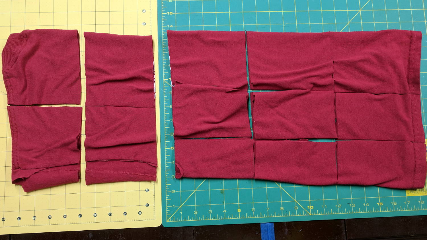
    Small wipes made from worn-out cotton t-shirts absorb most shop liquids, don’t overstay their welcome after short projects, and prevent the deep emotional attachment leaving swarf in the clothes washer. Scissors cutting gets tedious, so mooch a rotary cutter and slash away:

    T-shirt shop rags
    T-shirt shop rags

    Synthetic fabrics don’t work nearly as well as cotton, so pay attention to the labels.


  • Plotter Grit Wheel Bushings

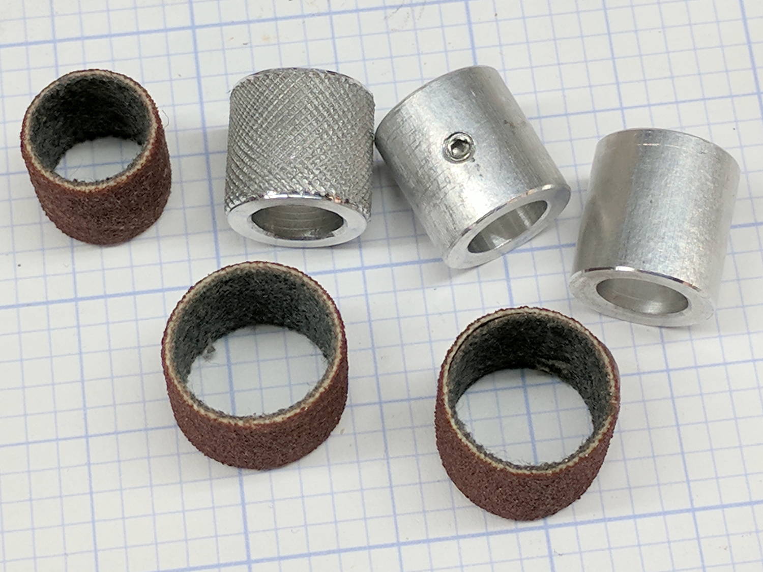
    As part of recommissioning the lathe tailstock, I made some bushings to adapt Dremel sanding drums bands to an 8 mm shaft (in imitation of the grit drive wheels on the HP plotter):

    Plotter Y bushing - samples
    Plotter Y bushing – samples

    They’re not all the same because the lad who’s building the plotter got to turn out his own bushings. We think the knurled version, with a setscrew to lock it on the shaft, will work better than adhesive-bonding the drum to the bushing.

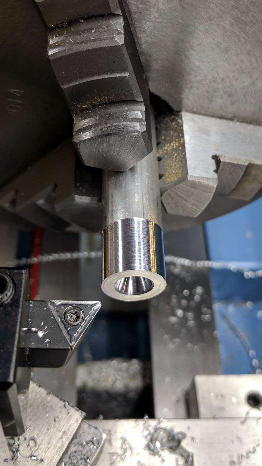
    The overall process starts with a rough 1/2 inch aluminum rod. Skim-cut to get a concentric surface and face the end smooth:

    Plotter Y bushing - facing
    Plotter Y bushing – facing

    Then knurl it:

    Plotter Y bushing - knurling
    Plotter Y bushing – knurling

    The skim cut makes the aluminum rod a loose fit inside the sanding band, but the knurling enlarges the diameter enough to make it a firm press fit and I think it’ll have enough traction to stay in place.

    FWIW, the wheels in the LittleMachineShop knurling tool seem pretty bad: the central holes aren’t quite concentric with the cutting edge, the bores are a loose fit on the mounting screws, the wheels are much narrower than the slots they ride in, so they wobble uncontrollably. It’s not a fatal flaw, but they definitely produce a sub-par knurl.

    Face off the front, cut the knurling down at each end, then part it off:

    Plotter Y bushing - cutoff
    Plotter Y bushing – cutoff

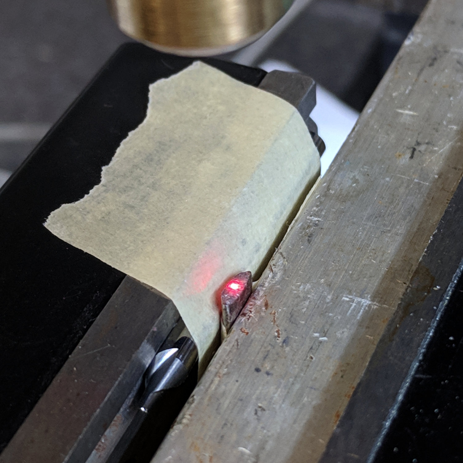
    Clamp it in the Sherline mill, laser-spot the edges, set the origin in the middle, and center drill:

    Plotter Y bushing - center drill
    Plotter Y bushing – center drill

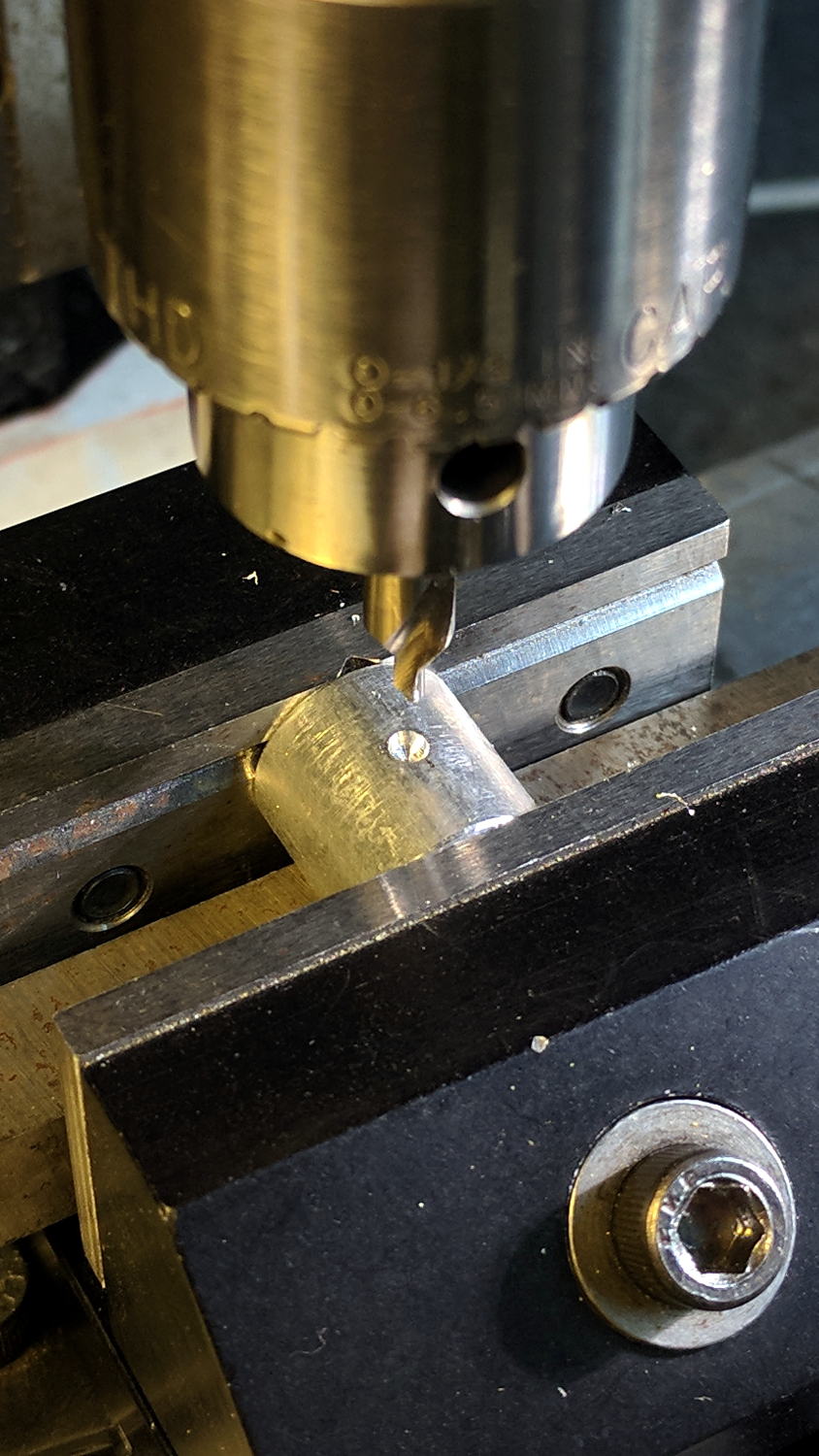
    Drill and tap for a teeny M3 setscrew:

    Plotter Y bushing - tapping
    Plotter Y bushing – tapping

    Clean out the chips, debur the hole, install the setscrew, and you’re half-done: do it again to get the second drive roller!


  • NEMA17 Motor and Bearing Mounts

    As part of coaching a student (and his father!) on their incredibly ambitious build-a-plotter-from-scratch project, I suggested stealing using HP’s grit-wheel paper drive, rather than fiddling with guide rods to move either the pen carrier or the entire paper platform. Dremel sanding drums seem about the right size and they had an 8 mm shaft harvested from a defunct printer, so a pair of mounts moves the project along:

    NEMA17 and Bearing Mounts - Slic3r preview
    NEMA17 and Bearing Mounts – Slic3r preview

    The motor mount code is a hack job from my old NEMA17 mount and the code has a lot not to like. The bearing mount puts the bearing on the proper centerline using brute force copypasta and depends on friction to hold it in place. The two models should be integrated into the same file, the shaft centerline shouldn’t involve the printed thread width, and blah blah blah:

    NEMA17 motor and bearing mounts
    NEMA17 motor and bearing mounts

    I had him turn the shaft adapter from an aluminum rod in the mini-lathe: he’s hooked.

    The OpenSCAD source code as a GitHub Gist:

    // Ball bearing mount
    // Ed Nisley KE4ZNU 2017-10-09
    //– Extrusion parameters
    ThreadThick = 0.20;
    ThreadWidth = 0.40;
    HoleWindage = 0.2; // enlarge hole dia by this amount
    function IntegerMultiple(Size,Unit) = Unit * ceil(Size / Unit);
    Protrusion = 0.1; // make holes look good and joints intersect properly
    //– Useful sizes
    inch = 25.4;
    Tap10_32 = 0.159 * inch;
    Clear10_32 = 0.190 * inch;
    Head10_32 = 0.373 * inch;
    Head10_32Thick = 0.110 * inch;
    Nut10_32Dia = 0.433 * inch;
    Nut10_32Thick = 0.130 * inch;
    // Bearing sizes
    ID = 0;
    OD = 1;
    LENGTH = 2;
    Bearing = [8.0,22.0,7.0];
    ShaftHeight = IntegerMultiple(25.2,ThreadWidth); // arbitrary or copied from motor mount
    WallThick = 3.0;
    //– Mount Sizes
    MountSize = Bearing[OD] + 2*WallThick;
    BaseThick = max(WallThick,ShaftHeight – MountSize/2); // baseplate
    StandBoltHead = IntegerMultiple(Head10_32,2); // bolt head rounded up
    StandBoltClear = 1.25 * StandBoltHead;
    StandBoltOC = IntegerMultiple(MountSize + StandBoltClear,2);
    StandLength = StandBoltOC + StandBoltClear;
    StandThick = StandBoltClear + WallThick;
    StandHeight = MountSize + BaseThick;
    Cutout = (StandLength – MountSize)/2;
    echo(str("Stand Base: ",StandLength," x ",StandThick," x ",BaseThick));
    echo(str("Stand Bolt OC: ",StandBoltOC));
    echo(str("Shaft Height:",ShaftHeight));
    //———————-
    // Useful routines
    module PolyCyl(Dia,Height,ForceSides=0) { // based on nophead's polyholes
    Sides = (ForceSides != 0) ? ForceSides : (ceil(Dia) + 2);
    FixDia = Dia / cos(180/Sides);
    cylinder(r=(FixDia + HoleWindage)/2,
    h=Height,
    $fn=Sides);
    }
    //———————-
    // Put it together
    module BearingMount() {
    difference() {
    translate([BaseThick/2,0,StandThick/2])
    cube([StandHeight,StandLength,StandThick],center=true);
    translate([0,0,-Protrusion])
    PolyCyl(Bearing[OD],(StandThick + 2*Protrusion));
    for (j=[-1,1]) // cutouts over bolts
    translate([-(StandHeight/2 – ShaftHeight + WallThick),
    j*(StandLength/2 – Cutout/2 + Protrusion/2),
    (WallThick + StandThick/2)])
    cube([StandHeight,
    Cutout + Protrusion,
    StandThick],center=true);
    for (j=[-1,1]) // stand bolt holes – base
    translate([(MountSize/2 – Protrusion),
    j*StandBoltOC/2,
    WallThick + StandBoltClear/2])
    rotate([0,90,0])
    rotate(180/6)
    PolyCyl(Clear10_32,BaseThick + 2*Protrusion,6);
    for (j=[-1,1]) // stand bolt holes – back
    translate([0,j*StandBoltOC/2,-Protrusion])
    rotate(180/6)
    PolyCyl(Clear10_32,StandThick + 2*Protrusion,6);
    translate([0,-(MountSize/2 – ThreadWidth/2),(StandThick – WallThick)/2 + WallThick])
    rotate([90,180,0])
    linear_extrude(ThreadWidth,convexity=10)
    text(text=str(ShaftHeight),size=6,spacing=1.20,font="Arial",halign="center",valign="center");
    }
    }
    //———————-
    // Build it
    BearingMount();
    // NEMA 17 stepper mount
    // Ed Nisley KE4ZNU August 2011
    // Tweaked & thinned 2017-10-09
    //– Extrusion parameters
    ThreadThick = 0.25;
    ThreadWidth = 0.4;
    HoleWindage = 0.3; // enlarge hole dia by this amount
    function IntegerMultiple(Size,Unit) = Unit * ceil(Size / Unit);
    Protrusion = 0.1; // make holes look good and joints intersect properly
    //– Useful sizes
    inch = 25.4;
    Tap10_32 = 0.159 * inch;
    Clear10_32 = 0.190 * inch;
    Head10_32 = 0.373 * inch;
    Head10_32Thick = 0.110 * inch;
    Nut10_32Dia = 0.433 * inch;
    Nut10_32Thick = 0.130 * inch;
    NEMA17_ShaftDia = 5.0;
    NEMA17_ShaftLength = 24.0;
    NEMA17_PilotDia = 0.866 * inch;
    NEMA17_PilotLength = 0.080 * inch;
    NEMA17_BCD = 1.725 * inch;
    NEMA17_BoltDia = 3.5;
    NEMA17_BoltOC = 1.220 * inch;
    //– Mount Sizes
    MountWidth = IntegerMultiple(NEMA17_BCD,ThreadWidth); // use BCD for motor clearance
    MountThick = IntegerMultiple(4.0,ThreadThick); // for stiffness
    MountBoltDia = 3.0;
    StandThick = 3.0; // baseplate
    StrutThick = IntegerMultiple(3.0,ThreadWidth); // sides holding motor mount
    UprightLength = MountWidth + 2*StrutThick;
    StandBoltHead = IntegerMultiple(Head10_32,5); // bolt head rounded up
    StandBoltOC = IntegerMultiple(UprightLength + 2*StandBoltHead,5);
    StandLength = StandBoltOC + 2*StandBoltHead;
    StandWidth = 2*StandBoltHead;
    StandBoltClear = (StandLength – UprightLength)/2; // flat around bolt head
    MotorRecess = StandWidth – MountThick;
    ShaftHeight = IntegerMultiple(StandThick + MountWidth/2,ThreadWidth);
    echo(str("Stand Base: ",StandLength," x ",StandWidth," x ",StandThick));
    echo(str("Stand Bolt OC: ",StandBoltOC));
    echo(str("Shaft Height:",ShaftHeight));
    echo(str("Strut Thick: ",StrutThick));
    //———————-
    // Useful routines
    module PolyCyl(Dia,Height,ForceSides=0) { // based on nophead's polyholes
    Sides = (ForceSides != 0) ? ForceSides : (ceil(Dia) + 2);
    FixDia = Dia / cos(180/Sides);
    cylinder(r=(FixDia + HoleWindage)/2,
    h=Height,
    $fn=Sides);
    }
    //———————-
    // Model
    module MotorMount() {
    difference() {
    translate([StandThick/2,0,StandWidth/2])
    cube([(MountWidth + StandThick),StandLength,StandWidth],center=true);
    translate([-Protrusion/2,0,StandWidth – (MotorRecess – Protrusion)/2])
    cube([(MountWidth + Protrusion),MountWidth,(MotorRecess + Protrusion)],center=true);
    translate([0,0,-Protrusion]) // pilot hole
    PolyCyl(NEMA17_PilotDia,(MountThick + 2*Protrusion));
    for (i=[-1,1]) // motor bolt holes
    for (j=[-1,1])
    translate([i*NEMA17_BoltOC/2,j*NEMA17_BoltOC/2,-Protrusion])
    PolyCyl(MountBoltDia,(MountThick + 2*Protrusion),6);
    for (j=[-1,1]) // cutouts over bolts
    translate([-Protrusion/2,
    j*((StandLength – StandBoltClear)/2 + Protrusion/2),
    StandWidth/2])
    cube([(MountWidth + Protrusion),
    (StandBoltClear + Protrusion),
    (StandWidth + 2*Protrusion)],center=true);
    for (j=[-1,1]) // stand bolt holes
    translate([(MountWidth/2 – Protrusion),j*StandBoltOC/2,StandWidth/2])
    rotate([0,90,0])
    rotate(180/6)
    PolyCyl(Clear10_32,StandThick + 2*Protrusion,6);
    translate([0,-(UprightLength/2 – ThreadWidth/2),StandWidth/2])
    rotate([90,180,0])
    linear_extrude(ThreadWidth,convexity=10)
    text(text=str(ShaftHeight),size=6,spacing=1.20,font="Arial",halign="center",valign="center");
    }
    }
    //———————-
    // Build it
    MotorMount();