Ed Nisley's Blog: Shop notes, electronics, firmware, machinery, 3D printing, laser cuttery, and curiosities. Contents: 100% human thinking, 0% AI slop.
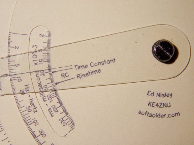
The original Tektronix Circuit Computer cursor is a floppy sheet of plastic with a hairline printed on it. I’m making the homage version from 0.5 mm PETG sheet with an engraved hairline:
Tek CC – radial text example
But I don’t foresee enough ahem production volume to justify making a punch-and-die to cut the thing out, so I need a milling fixture to hold the sheet in place while I have my way with it.
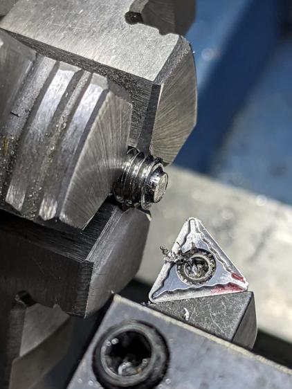
Start by squaring up a suitably sized scrap from the Box o’ Plastic Scrap:
Tek CC – Cursor milling fixture – squaring sides
It need not be particularly square, but getting rid of the ragged edges seemed like a Good Idea. I think it’s polycarbonate and, yes, it’s just about that green in real life.
Align it square-ish to the tooling plate and drill three #7 holes on 1.16 inch centers to line up with the plate and clear the Sherline’s 10-32 screws:
Tek CC – Cursor milling fixture – hole drilling
The two outer holes will clamp the fixture to the table. The third hole may be useful to clamp a stack of cursors to the fixture, should I need more than a few.
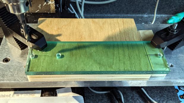
Screw it to the tooling plate, mill the outline of the cursor into the fixture, apply a layer of double sticky tape, then cut out the cursor outline so the milling bit won’t accrete a giant whirling ball of adhesive & swarf:
Tek CC – Cursor milling fixture – 2-side tape applied
I milled the perimeter 2 mm deep, anticipating a 1 mm cut depth for the cursor, and milled a small step inside the perimeter by compiling the GCMC code with a 2.5 mm cutter diameter instead of the actual 3.175 mm. I tweaked the cursor code for proper offset milling, about which more later.
With the tape in place, it’s not entirely obvious this will work the way I expect, but it wasn’t too difficult.
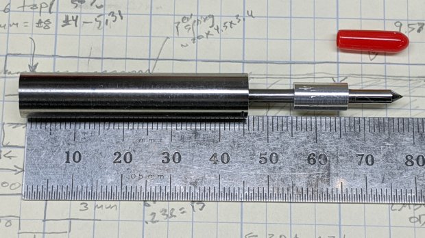
Although I shouldn’t have used a hardened shaft for the case, the rest of the diamond drag tool holder worked out well enough:
Sherline Diamond Drag Holder – assembled
The dimension doodle shows what’s inside and gives some idea of the sizes:
Sherline Diamond Drag Holder – dimension doodles
From left to right, it’s an M6×1.0 setscrew to adjust the spring preload, a spring harvested from a cheap clicky ballpoint pen, a machined cap, a 3 mm rod (which should be a hardened & ground shaft, but isn’t) surrounded by a pair of LM3UU linear bearings, a machined coupler, and the stub of a diamond engraving tool’s shank.
Tapping 15 mm of M6×1.0 thread inside of the case took an unreasonable amount of grunt. Next time, brass.
The setscrew gets a little boss to hold the spring away from the adjacent threads in the case:
Sherline Diamond Drag Holder – setscrew spring boss
The little machined cap has a somewhat longer spring guide to prevent buckling:
Sherline Diamond Drag Holder – shank cap spring guide
The spring fits snugly on the slightly enlarged section inside the last few coils, with the rest being a loose fit around the guide. When the spring is fully compressed, it’s just slightly longer than the guide and can’t buckle to either side.
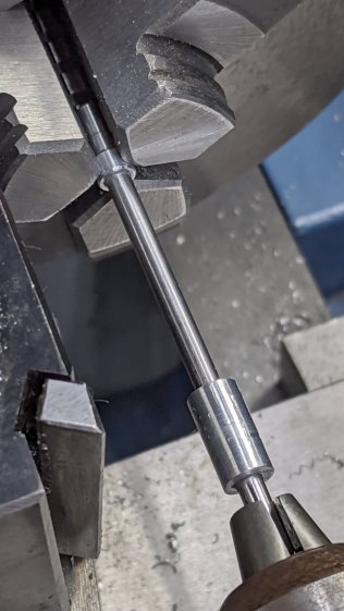
The cap gets epoxied onto the 3 mm rod with some attention to proper alignment:
Sherline Diamond Drag Holder – shank cap alignment
The other end of the rod has a 3 mm thread, which would be a serious non-starter on a hardened rod.
The shortened diamond tool shank gets epoxied into the gizmo connecting it to the now-threaded rod, again with some attention paid to having it come out nicely coaxial:
The LM3UU bearings got epoxied into the case, because I don’t have a deep emotional attachment to them.
Unscrew diamond tool, push spring onto cap, drop rod through bearings, crank setscrew more-or-less flush with the end of the case, screw diamond in place with some weak threadlock, add oil to rod, work it a few times to settle the bearings, and it’s all good.
The spring rate works out to 230 g + 33 g/mm for deflections between 1.0 mm (263 g) and 3.5 mm (346 g), so it’s in the same ballpark as the diamond tools on the MPCNC and CNC 3018.
Note: WordPress just “improved” their post editor, which has totally wrecked the image alignment. They’re all set to “centered” and the editor says they are, but they’re not. It’s a free blog and I’m using one of their ancient / obsolete / unsupported themes, so I must update the theme. Bleh.
Our Young Engineer recently rented a house, now knows why our sinks have CNC-machined strainers, and asked for something better than the disgusting stainless mesh strainer in the kitchen sink.
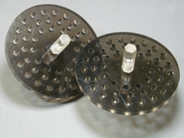
Being a doting father, I turned out a pair to get a pretty one:
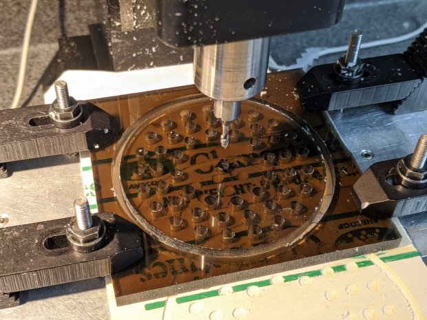
CNC Sink Strainer – overview
They’re made from the same scrap smoked acrylic as the ones in our sinks:
CNC Sink Strainer
They’re definitely upscale from the (not watertight!) 3D printed version I built for a Digital Machinist column to explain OpenSCAD modeling:
Strainer plate fill
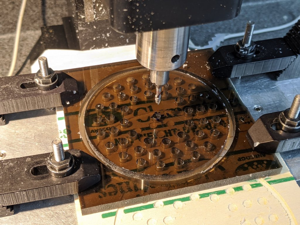
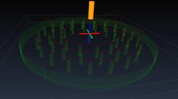
This time around, though, I rewrote the subtractive design in GCMC, with helical milling for all the holes to eliminate the need to change tools:
Sink Strainer – tool path simulation – CAMotics
They’re done on the Sherline, because it has real clamps:
CNC Sink Strainer – on Sherline
Four tabs eliminated the need to reclamp the stock before cutting the perimeter, but I should have ramped, not plunged, through the final cut between the tabs:
CNC Sink Strainer – tab surface fracture
The handles come from the same chunk of hex acrylic as before, eyeballed to length, tapped 8-32, and secured with acrylic adhesive.
This file contains hidden or bidirectional Unicode text that may be interpreted or compiled differently than what appears below. To review, open the file in an editor that reveals hidden Unicode characters.
Learn more about bidirectional Unicode characters
We bought the best-looking (pronounced “least bashed”) pair of hulking five-drawer industrial-strength HON Brigade Lateral File Cabinets from the local ReStore outlet’s assortment for Mary’s quilting fabric stash. They came with a steep discount, barely fit inside the Forester, caused minor interior trim damage, and should organize her entire stash.
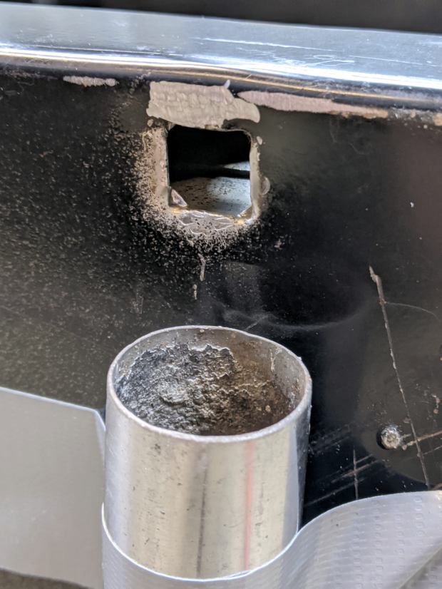
One cabinet lost a foot nut at some point in its 16 year history:
HON Lateral File – foot hole – weld nugget filed
The surviving foot nuts sported two weld nuggets apiece:
HON Lateral File – OEM front foot
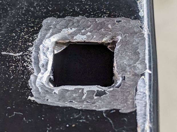
The hole had the remains of one nugget at the top left and looks like a manufacturing defect to me. Of course, we’re (at least) the second owners and the usual lifetime warranty no longer applies.
I can fix that.
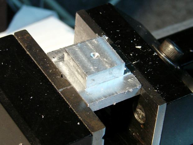
Bandsaw a 1×¾ inch rectangle from 3/8 inch aluminum plate to match the surviving foot nut (which is steel, but aluminum will suffice for our needs). Break the edges, clamp in the Sherline, and mill a square protrusion to match the square-ish hole:
HON Lateral File – square nut – rough cut
Drill a 17/64 inch hole (looser than the nominal F drill, because I’m a sissy) for a flat-head bolt from the Drawer o’ 3/8-16 Bolts, tap, and clean up.
A trial fit showed the nugget had to go before the nut would come even close to fitting flat into the hole:
HON Lateral File – foot hole – grinding
The sheet metal around the hole had absorbed at least one mighty blow pushing the entire surface inward behind the front edge. To compensate, recess the nut’s front edge and slope the sides with a Dremel wheel to let the bottom face sit level:
HON Lateral File – square nut – taper grinding
Another trial fit showed the need for more recess:
HON Lateral File – square nut – deeper cut
Another spate of grinding made it sit mostly level on the decidedly non-level surface around the hole:
HON Lateral File – square nut – ready to install
The beveled corners fit inside the swaged hole corners.
Grind paint / crud off the sheet metal and roughen the surface for good epoxy griptivity:
HON Lateral File – foot hole – ready for install
Stand the cabinet top-side-down to make the bottom level. I wish the basement had one more course of block, but it’s not to be.
Butter the nut with JB Weld epoxy, plunk it in place, apply excess epoxy to make a fillet around the edges, apply duct tape to guy the top of the bolt level-ish, and let it cure:
HON Lateral File – square nut – epoxy curing
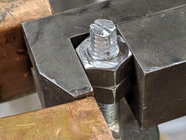
After the epoxy stiffened enough to hold its position, remove the bolt, file a crude ¼ inch hex, and saw a screwdriver slot to make it match the other feet:
HON Lateral File – new foot hex head
Not the fanciest job I’ve ever done, but it now behaves just like the other ones and it’s all good. The HON Storage Files FAQ points to a Troubleshooting Guide showing how to level the thing with a hex socket from inside the bottom drawer.
The flat heads on those bolts are basically 25 mm OD steel plates calling for fuzzy felt bumpers on the Sewing Room’s wood floors. When properly leveled, the front will be ⅛ inch higher than the rear. Although they suggest a pencil should roll toward the back, the top sheet metal on this one may be sufficiently warped to confuse the issue; I have a long level well suited to the task.
The original dimension doodle includes metric offsets for cutting with a ¼ inch end mill:
HON Foot nut – dimension doodles
All in all, a satisfying day in the Basement Shop …
A test to mill the pivot hole in 0.5 mm PETG sheet worked perfectly:
Tek CC – cursor pivot hole milling
The cutter is a 3.175 mm = 1/8 inch router bit, one of a ten-pack that came with the CNC 3018 and to which I have no deep emotional attachment, held in a collet in the Sherline. The hole is 5.5 mm to fit an eyelet. The PETG is taped to a thin plywood scrap.
The hole happened by feeding G-Code manually into LinuxCNC, after touching off XYZ=0 at the center of the pivot and jogging up a bit:
g0 y-1.1625
f1000
g0 z0.5
g2 p5 z-1.5 i0 j1.1625
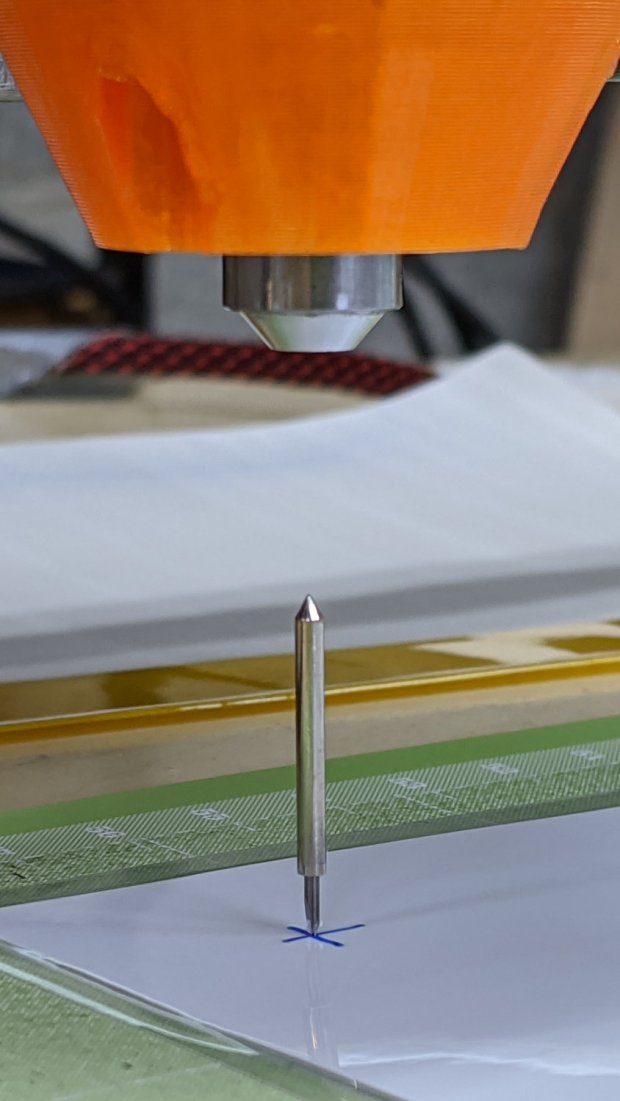
Yes, I engraved the hairline using a diamond drag tool on the CNC 3018, cut the cursor outline with a drag knife on the MPCNC, then milled the pivot hole on the Sherline. This seems way over the top, even to me, but that’s just how the tooling worked out right now.
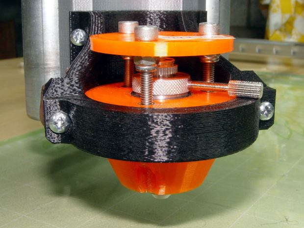
In actual practice, I’d probably mill a stack of cursors and pivot holes on the Sherline in one setup, then engrave the hairlines in a suitable fixture. I think I know enough to fit a spring-loaded diamond drag bit into the Sherline’s 10 mm ID spindle or, worst case, conjure a block for the Z-axis carrier in place of the entire spindle mount.
At least now I can remember what I did to make the hole.
This happened a few times before, because my fingers don’t fit neatly inside the drag knife holder to tighten the lock ring:
Drag Knife – LM12UU ground shaft – assembled
[Update: The lock ring keeps the holder at a fixed position inside the 12 mm shaft and doesn’t affect the blade directly. When the ring works loose, the threaded holder can rotate to expose more blade and, in this case, stab deeper into the target. ]
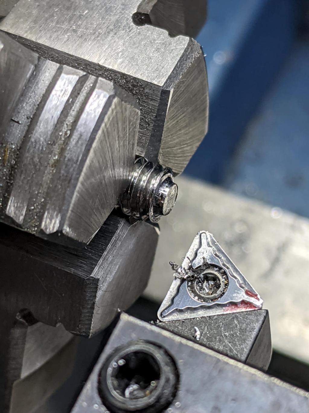
So I turned & knurled an aluminum ring, then tapped a 3×0.5 mm hole for a lock screw plucked from the Drawer o’ Random M3 Screws:
Drag Knife – lock screw – side
A view looking along the screw shows a bit more detail around the spring:
Drag Knife – lock screw – front
The general idea is to set the blade extension, then tighten the lock screw to hold it in place, without relying on the original brass lock ring, shown here while cutting a boss for the spring:
Drag Knife – turning spring recess
The lock screw’s knurled handle just barely kisses the NPCNC’s black tool holder ring, so my guesstimated measurements were a bit off. Clamping the knife holder one itsy higher in the tool holder solved the problem.
I cranked on 300 g of spring preload and, squashed like that, the spring’s rate is now 75 g/mm. Cutting at Z=-1 mm should suffice for laminated paper slide rule decks.
The original sizing doodle:
Drag Knife Holder – lock screw ring doodle
The short 18 mm section clears the inside of the LM12UU bearing, although it could be a millimeter shorter. The 19 mm section comes from the 3/4 inch aluminum rod I used, skim-cut to clean it up.
If I ever remake this thing, it needs a major re-think to get all the dimensions flying in formation again.