The 12 mm drag knife holder on the left slides nicely in an LM12UU bearing:
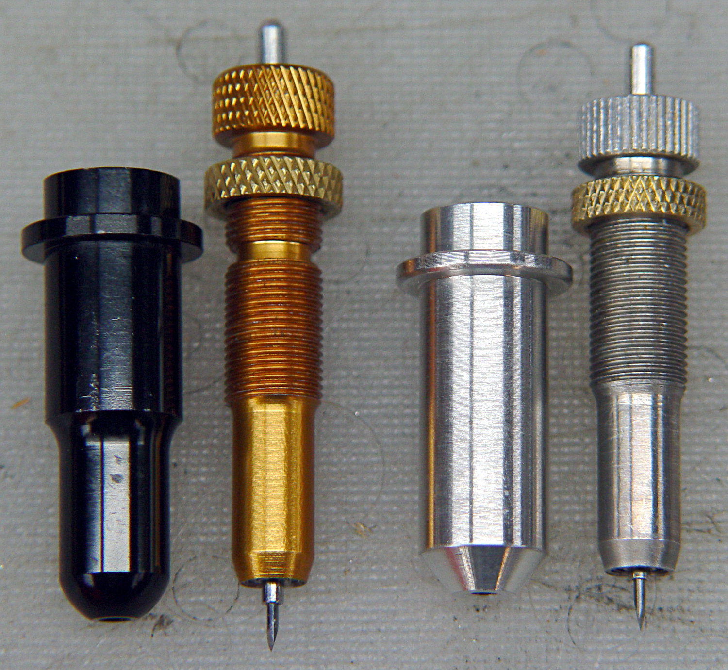
However, its aluminum body isn’t really intended as a bearing surface and it extends only halfway through the LM12UU, so I finally got around to modifying the 11.5 mm body on the right to fit into a section of 12 mm ground shaft:

The general idea is to turn the body down to 10 mm OD; the picture shows the first pass over the nose after turning the far end down and removing the flange in the process. Exact concentricity of both ends isn’t important (it gets epoxied into a 10 mm hole through the 12 mm ground shaft), but it came out rather pretty:

The ground shaft started as a pen holder:
I knocked off the ring and bored the interior to fit the 10 mm knife body. The large end of the existing bore came from a 25/64 inch = 9.92 mm drill, so it was just shy of 10.0 mm, and I drilled the small end upward from 0.33 inch = 8.4 mm.
The smallest trio of a new set of cheap carbide boring bars allegedly went into a 5/16 inch = 7.9 mm bore, but I had to file the bar body down and diamond-file more end relief into the carbide for clearance inside the drilled hole:

I blued the bit, kissed it against the drilled bore, filed off whatever wasn’t blued, and iterated until the carbide edge started cutting. Sissy cuts all the way, with no pix to show for all the flailing around.
Epoxying the turned-down drag knife body into the shaft: anticlimactic.
The solid model features a stylin’ tapered snout:

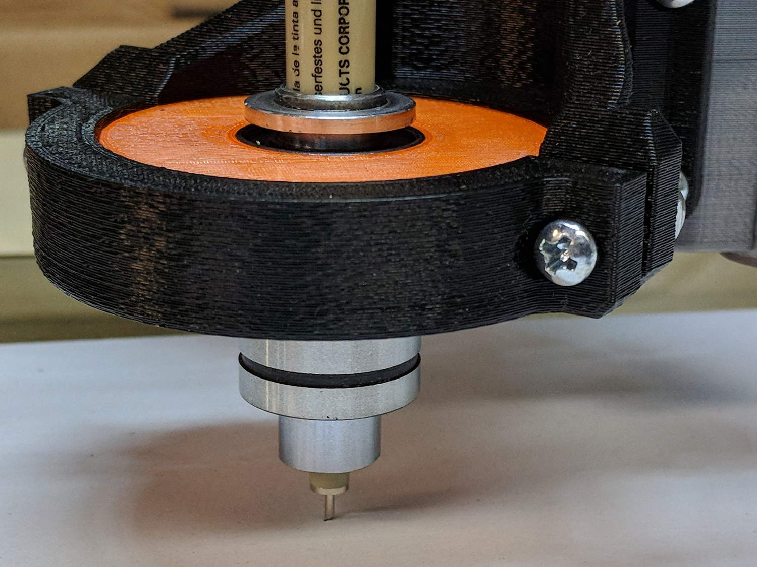
Which gets an LM12UU bearing rammed into place:

The steel block leaves the bearing flush with the plastic surface, rather than having it continue onward and indent itself into the wood; I can learn from my mistakes.
The new idea: a single spring pressing the knife holder downward, reacting against a fixed plastic plate:
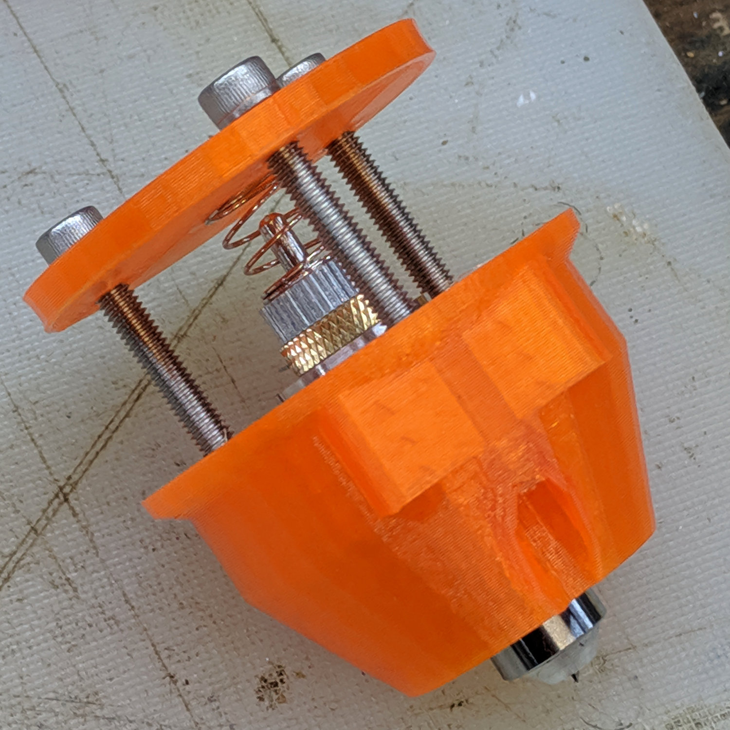
Unlike the previous design, the upper plate doesn’t move, so there’s no problem caused by sliding along the screw threads. I should run nylock nuts up against the plate to keep it in place, stiffen the structure, and provide some friction to keep the screws from loosening.
The top of the knife holder now has a boss anchoring the spring:

As you’d expect, the ground shaft slides wonderfully in the bearing, because that’s what it’s designed to do, and the knife has essentially zero stiction and friction at any point along the bearing, which is exactly what I wanted.
The spring, from the same assortment as all the others, has a 48 g/mm rate.
The OpenSCAD source code as a GitHub Gist:
| // Drag Knife Holder using LM12UU linear bearing | |
| // Ed Nisley KE4ZNU – 2019-04-26 | |
| // 2019-06-01 Taper the nose | |
| Layout = "Build"; // [Build, Show, Puck, Mount, Plate] | |
| /* [Extrusion] */ | |
| ThreadThick = 0.25; // [0.20, 0.25] | |
| ThreadWidth = 0.40; // [0.40] | |
| /* [Hidden] */ | |
| Protrusion = 0.1; // [0.01, 0.1] | |
| HoleWindage = 0.2; | |
| inch = 25.4; | |
| function IntegerMultiple(Size,Unit) = Unit * ceil(Size / Unit); | |
| ID = 0; | |
| OD = 1; | |
| LENGTH = 2; | |
| //- Adjust hole diameter to make the size come out right | |
| module PolyCyl(Dia,Height,ForceSides=0) { // based on nophead's polyholes | |
| Sides = (ForceSides != 0) ? ForceSides : (ceil(Dia) + 2); | |
| FixDia = Dia / cos(180/Sides); | |
| cylinder(r=(FixDia + HoleWindage)/2,h=Height,$fn=Sides); | |
| } | |
| //- Dimensions | |
| // Basic shape of DW660 snout fitting into the holder | |
| // Lip goes upward to lock into MPCNC mount | |
| Snout = [44.6,50.0,9.6]; // LENGTH = ID height | |
| Lip = 4.0; // height of lip at end of snout | |
| // Knife holder & suchlike | |
| KnifeBody = [12.0,18.0,2.0]; // body OD, flange OD, flange thickness | |
| Spring = [9.5,10.0,3*ThreadThick]; // compression spring loading knife blade | |
| PinAccess = 4.0; // hole to reach knife ejection pin | |
| WallThick = 4.0; // minimum thickness / width | |
| Screw = [4.0,8.5,25.0]; // thread ID, washer OD, length | |
| Insert = [4.0,6.0,10.0]; // brass insert | |
| Bearing = [12.0,21.0,30.0]; // linear bearing body | |
| Plate = [PinAccess,Snout[OD] – WallThick,WallThick]; // spring reaction plate | |
| echo(str("Plate: ",Plate)); | |
| SpringSeat = [0.56,7.2,2*ThreadThick]; // wire = ID, coil = OD, seat depth = length | |
| PuckOAL = max(Bearing[LENGTH],(Snout[LENGTH] + Lip)); // total height of DW660 fitting | |
| echo(str("PuckOAL: ",PuckOAL)); | |
| Key = [Snout[ID],25.7,(Snout[LENGTH] + Lip)]; // rectangular key | |
| NumScrews = 3; | |
| //ScrewBCD = 2.0*(Bearing[OD]/2 + Insert[OD]/2 + WallThick); | |
| ScrewBCD = (Snout[ID] + Bearing[OD])/2; | |
| NumSides = 9*4; // cylinder facets (multiple of 3 for lathe trimming) | |
| module DW660Puck() { | |
| translate([0,0,PuckOAL]) | |
| rotate([180,0,0]) { | |
| cylinder(d=Snout[OD],h=Lip/2,$fn=NumSides); | |
| translate([0,0,Lip/2]) | |
| cylinder(d1=Snout[OD],d2=Snout[ID],h=Lip/2,$fn=NumSides); | |
| cylinder(d=Snout[ID],h=(Snout[LENGTH] + Lip),$fn=NumSides); | |
| translate([0,0,(Snout[LENGTH] + Lip) – Protrusion]) | |
| cylinder(d1=Snout[ID],d2=2*WallThick + Bearing[OD],h=PuckOAL – (Snout[LENGTH] + Lip),$fn=NumSides); | |
| intersection() { | |
| translate([0,0,0*Lip + Key.z/2]) | |
| cube(Key,center=true); | |
| cylinder(d=Snout[OD],h=Lip + Key.z,$fn=NumSides); | |
| } | |
| } | |
| } | |
| module MountBase() { | |
| difference() { | |
| DW660Puck(); | |
| translate([0,0,-Protrusion]) // bearing | |
| PolyCyl(Bearing[OD],2*PuckOAL,NumSides); | |
| for (i=[0:NumScrews – 1]) // clamp screws | |
| rotate(i*360/NumScrews) | |
| translate([ScrewBCD/2,0,-Protrusion]) | |
| rotate(180/8) | |
| PolyCyl(Insert[OD],2*PuckOAL,8); | |
| } | |
| } | |
| module SpringPlate() { | |
| difference() { | |
| cylinder(d=Plate[OD],h=Plate[LENGTH],$fn=NumSides); | |
| translate([0,0,-Protrusion]) // ejection pin hole | |
| PolyCyl(PinAccess,2*Plate[LENGTH],NumSides); | |
| translate([0,0,Plate[LENGTH] – Spring[LENGTH]]) // spring retaining recess | |
| PolyCyl(Spring[OD],Spring[LENGTH] + Protrusion,NumSides); | |
| for (i=[0:NumScrews – 1]) // clamp screws | |
| rotate(i*360/NumScrews) | |
| translate([ScrewBCD/2,0,-Protrusion]) | |
| rotate(180/8) | |
| PolyCyl(Screw[ID],2*PuckOAL,8); | |
| if (false) | |
| for (i=[0:NumScrews – 1]) // coil positioning recess | |
| rotate(i*360/NumScrews) | |
| translate([ScrewBCD/2,0,-Protrusion]) | |
| rotate(180/8) | |
| PolyCyl(SpringSeat[OD],SpringSeat[LENGTH] + Protrusion,8); | |
| } | |
| } | |
| //—– | |
| // Build it | |
| if (Layout == "Puck") | |
| DW660Puck(); | |
| if (Layout == "Plate") | |
| SpringPlate(); | |
| if (Layout == "Mount") | |
| MountBase(); | |
| if (Layout == "Show") { | |
| MountBase(); | |
| translate([0,0,1.6*PuckOAL]) | |
| rotate([180,0,0]) | |
| SpringPlate(); | |
| } | |
| if (Layout == "Build") { | |
| translate([0,Snout[OD]/2,PuckOAL]) | |
| rotate([180,0,0]) | |
| MountBase(); | |
| translate([0,-Snout[OD]/2,0]) | |
| SpringPlate(); | |
| } |

Comments
7 responses to “MPCNC Drag Knife: Ground Shaft in LM12UU Bearing”
I’ve been looking forward to this iteration: it addresses the issues I (and presumably you) had thought of, and the payoff is that it didn’t just uncover new issues!
The anodized aluminum on the previous version just didn’t seem right. Now, to try it on reasonably stiff cardboard for quilting templates and vinyl for garden markers …
Nice work!
It’s significantly easier to show-n-tell this one! [grin]
[…] by the smooth running of the LM12UU drag knife mount, I chopped off another length of 12 mm […]
[…] LM12UU drag knife holder buries the blade ejector pin deep inside the […]
[…] the spring rates for the drag knife, diamond engraver, and collet pen holders by measuring the downforce every 0.5 mm (or […]