The Smell of Molten Projects in the Morning

Ed Nisley's Blog: Shop notes, electronics, firmware, machinery, 3D printing, laser cuttery, and curiosities. Contents: 100% human thinking, 0% AI slop.

Tag: Sherline

Sherline CNC mill

  • Fairing Arcs

    In CNC machining, at least the kind I do on my Sherline CNC mill, you can’t mill around acute inside corners: a round milling bit doesn’t fit into a straight-sided angle. You must add a fairing arc that smoothly connects the two sides; the catch is that “smooth” means it’s tangent to the sides. And EMC2 is really, really fussy about smooth, to the point where you can’t just wing it with a calculator and type in the numbers.

    Fairing arc doodles
    Fairing arc doodles

    There are nice analytic geometry methods for finding the intersection of two line segments, then laying in the arc that connects them, but this example weighs in at over two pages of G-Code. Mostly, what I need is an arc that connects a vertical or horizontal edge to an angled edge, so some simplification is in order.

    Herewith, the quick-and-dirty…

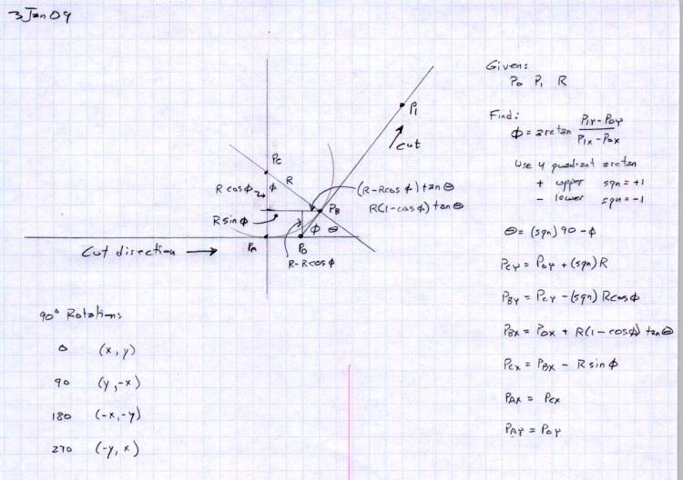
    The cutter enters from the left side, moving horizontally to the right, and will depart along the line toward P1, which might be the next corner of the part. The two material edges meet at P0, the vertex of the angle. The fairing arc is tangent to the two edges at PA and PB, centered at PC, and with a radius R.

    We know the coordinates of P0 and P1 and the arc radius. That radius must be larger than the cutter radius, as you can’t tuck a fat cutter into a narrow corner.

    The problem is to find PA, PB, and PC, so that we can write the G-code commands that travel along the sides & the arc.

    The first step is finding Φ (Phi), the angle between the outgoing edge and the X axis:

    Φ = arctan Δy/Δx = arctan (P1y – P0y) / (P1x – P0x)

    I’m pretty sure if you use a 4-quadrant arctan, as shown in the doodle, all the angles will work out perfectly on either side of the axis, but it’s easy enough to fake the signs to get the right answer in any specific case. If you wanted a general solution, you’d have a two-page subroutine, right?

    You’ll need the complement of that angle, hereinafter known as Theta:

    Θ = 90 – Φ

    Find the distances between various points using good old trig and right triangles:

    • CBx = R · sin Φ
    • CBy = R · cos Φ
    • P0PBy = R · (1 – cos Φ)
    • P0PBx = P0PBy · tan Θ

    Then the coordinates fall out thusly:

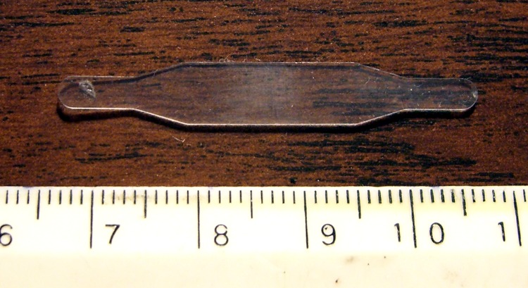
    Plastic Spring with Faired Corners
    Plastic Spring with Faired Corners
    • PCy = P0y + R
    • PBy = PCy – CBy
    • PBx = P0x + P0PBx
    • PCx = PBx – CBx
    • PAx = PCx
    • PAy = P0y

    Remember, you do not figure all this out with your calculator and plug the numbers into the G-code, not if you have any sense. If you have just a few corners, write the commands directly, otherwise gimmick up a little subroutine. Earlier versions of EMC2 used numbered parameters (#100), but now that you can have named parameters (#<_Fairing_Radius>), what’s holding you back?

    For example:

    #<_CBy>	= [#<_Fairing_Radius> * COS [#<_Phi>]]	(Y distance PC to PB)

    If your edge doesn’t come in from the left, then manual 90 degree rotations apply.

    0: (x,y) -> (x,y)
    90: (x,y) -> (y,-x)
    180: (x,y) -> (-x,-y)
    270: (x,y) -> (-y,x)

    If you’re using a CAD program to lay out your parts, all this is largely irrelevant. I hammer out the G-code for the simple 2-1/2-D parts I make by hand, so rounding off a few corners comes in handy.

    Because the lines & arc define the material edge contour, you can mill on either side of it and use cutter radius compensation to make the answer come out right. Works like a champ!

    For what it’s worth, the arc is tangent at PA and PB, making the line from PC to the corner (a.k.a. vertex) P0 the bisector of angle Φ. That’s not directly useful here, but keep it in mind when you solve similar problems.

    Update: As of mid-January, the newest trunk version of EMC2 can automagically insert fillets when cutter comp is turned on. That’ll be in the stable version in a while, after which I’ll need this math only for decorative fillets. That’s fine with me!

  • Sunglass Repair

    Making the fixture
    Making the fixture

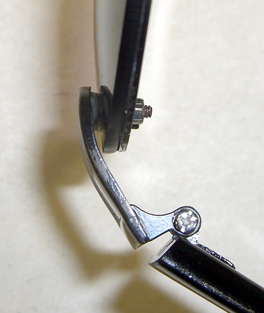
    One of the screws on Mary’s sunglasses came apart. Wonder of wonders, the nut fell off in the kitchen, made a click when it hit the floor, and we managed to collect all the pieces.

    The temples attach to the lens frame with two tiny screws apiece. The screw heads are slightly embedded in the temples, but you can see why this didn’t work nearly as well in practice as it did in the design studio.

    The trick is to align the screw properly so it fits through the lens and frame after the adhesive sets up. The holes are 6 mm on center and more-or-less 55 mils in diameter (obviously, they’re metric screws, but this is the US and we do the best we can with antique units).

    Clamping and curing
    Clamping and curing

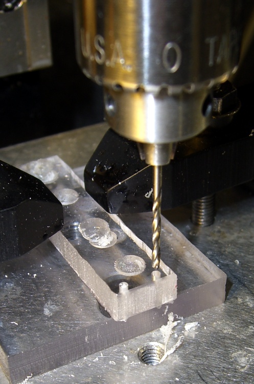
    That’s what CNC is all about: making it trivial to poke holes exactly 6 mm apart on center. I drilled two holes in some scrap acrylic sheet using Manual mode on my Sherline / EMC2 mill:

    g83 z-7 r1 q0.5 f100
    g0 x6
    g83 z-7 r1 q0.5 f100
    g0 z100

    I have it set to start up in metric units, which still seems to be legal here.

    cimg2858-sunglass-repair-success
    Success!

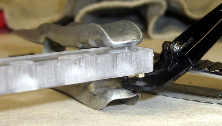
    Add a teeny dab of JB Weld, hold everything together overnight with a clothespin, and it’s all good in the morning.

    The trick is to check the leftover epoxy first to see if it’s fully cured before you move the actual piece.

    Memo to self: epoxy takes forever to cure at 55 F.

    Update: Pretty much as expected, that little dot of epoxy didn’t hold nearly as well as the original brazing. I tried a somewhat larger dot, but Mary was unhappy with the glasses anyway and we finally tossed ’em out.

    Of course I salvaged the screws & nuts & suchlike: you gotta have stuff!

  • Small Sherline Clamps

    Made six hold-down clamps for the Sherline mill, inspired by this much fancier project:

    http://www.sherline.com/tip5.htm

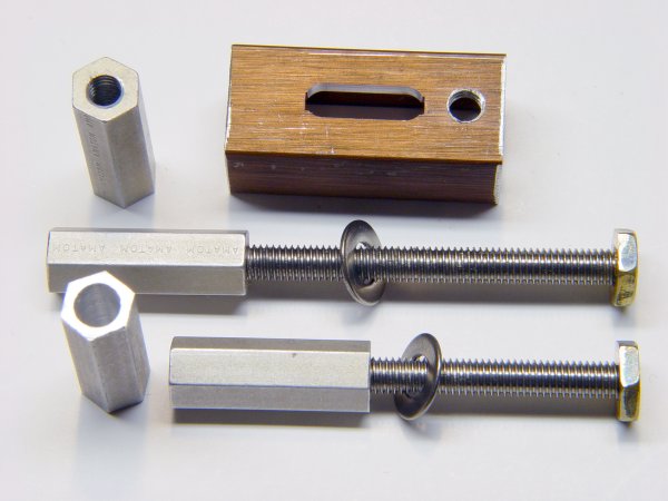
    Adapted Bookshelf Extrusion and Screws
    Adapted Bookshelf Extrusion and Screws

    He used steel clamps, brazed on little brass snippets, and used brass hex rod for the nuts. I hate machining steel, particularly in teeny pieces, and didn’t have any brass hex stock that small: improvisation was in order!

    So I sawed up an old aluminum bookshelf rail, CNC-ed the slot (more practice writing G-code), sawed the heads off some stainless 10-32 screws, and produced something that might work just as well.

    My stash has a lifetime supply of 10-24 brass nuts, so I jammed them on the end of the 10-32 screws in the back to act as pads against the mill table top. No finesse there…

    The T-slots aren’t quite deep enough for the nuts, though, so I milled 15 thou off each side of another six nuts and discovered, once again, that you can’t take an arbitrarily thin cut unless you have an arbitrarily sharp cutter… which, of course, I don’t. Made a plastic spacer to hold the nuts just high enough to nibble off the excess and just low enough to grip ’em in the mill vise. Did the whole thing without leaving embarrassing scars on the vise or ruining the cutter, much to my delight.

    Tapped the slenderized nuts 10-32 (how crude!) and applied green Loctite to the three goobered threads to lock the screws in place. The flats just clear the T-slots and the thickness is just barely OK, so I declared success.

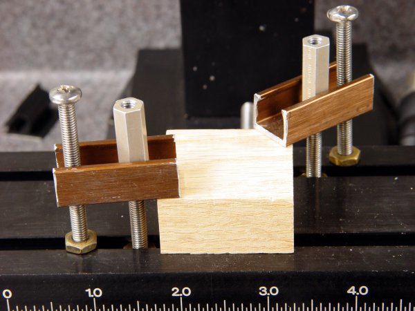
    Clamps In Action
    Clamps In Action

    The Good Idea in the original project lies in the long hex nuts. They’re drilled out about 3/4 of their length to clear the 10-32 screws, so you can just drop them on and spin a few times rather than tediously twisting them all the way down. My stash yielded some 2-inch aluminum standoffs tapped for 4-40 screws on each end; cut ’em in half, drilled out the raw end, drilled-and-tapped the existing holes to 10-32, and there they were.

    And, best of all, my fingers will smell like tapping lube for the rest of the month… ah, shop time!

    Update: You can cut a nice taper on the nose if you don’t like the relentless square aspect of those things or need a bit more clearance. They’re peeking into the sides of the bottom picture there, holding the sacrificial plate in place.