The Smell of Molten Projects in the Morning

Ed Nisley's Blog: Shop notes, electronics, firmware, machinery, 3D printing, laser cuttery, and curiosities. Contents: 100% human thinking, 0% AI slop.

Tag: Sherline

Sherline CNC mill

  • More Tommy Bar Handles

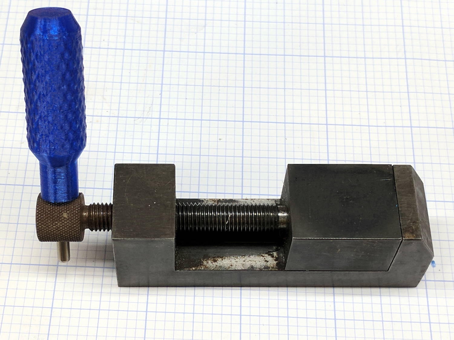
    Having used a nail for far too long, this is a definite step up for my machinist vises:

    Tommy Bar - machinist vise
    Tommy Bar – machinist vise

    The vise knob has a hole just barely passing a length of 3.4 mm = 9/64 inch mild steel rod from the Small Box o’ Cutoffs.

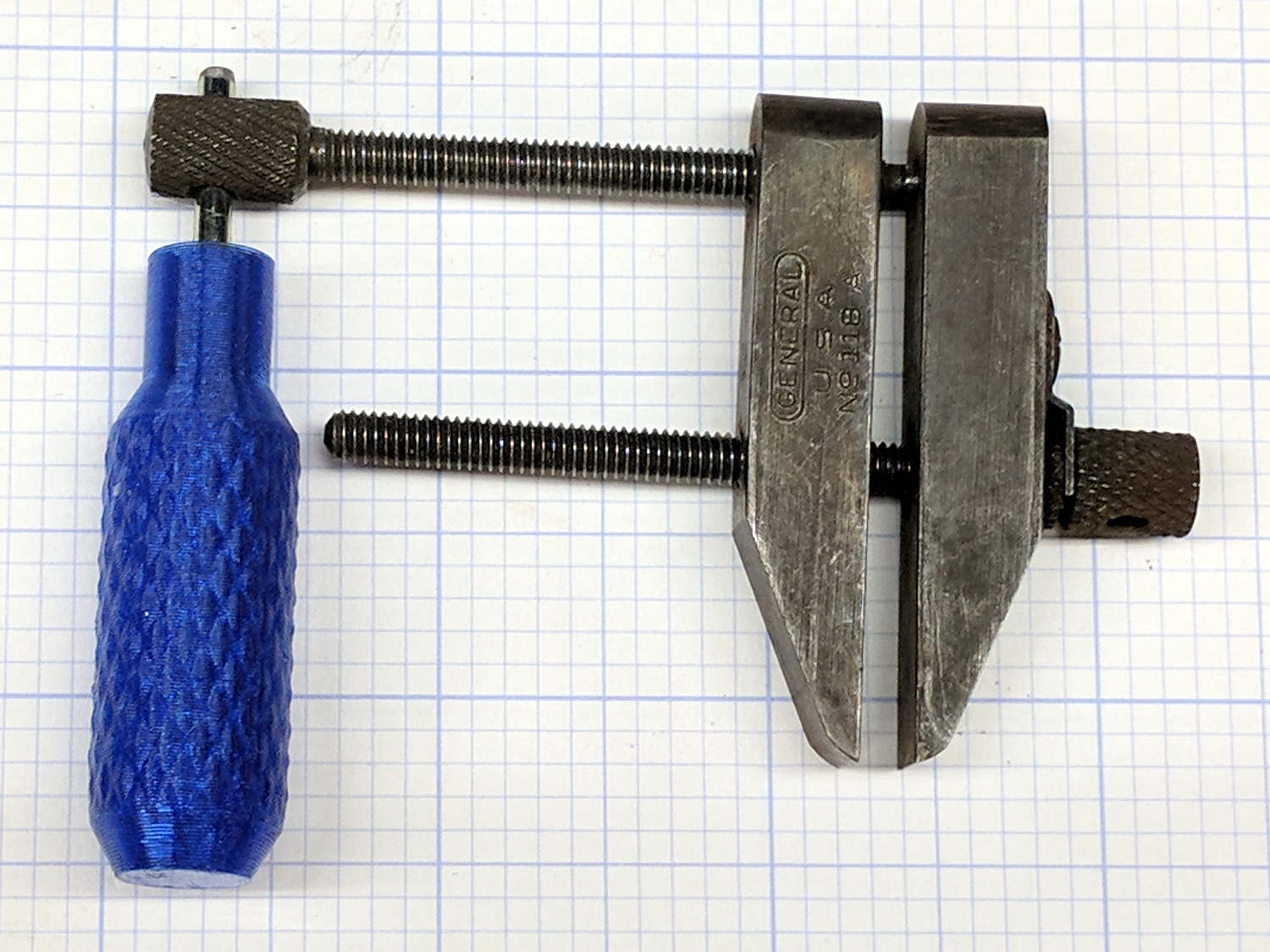
    While I was at it, I made a handle for the parallel jaw clamps:

    Tommy Bar - parallel jaw clamp
    Tommy Bar – parallel jaw clamp

    Those knobs pass a 3.0 mm = 1/8 inch rod, similarly sourced. Inexplicably, one clamp expected no more than a 7/64 inch rod; a brief introduction to Mr Drill Press persuaded it concerning the error of its ways.

    I should have made the handles distinctively different, because they’ll get mixed up in the box of vises & clamps. Next time, fer shure!

    The Tommy Bar handles use the same solid model as the Sherline Tommy Bars, with hole diameters as noted. Cyan PETG is definitely easier on the eye than red PLA, although it does fade into the background clutter around here.

  • Vacuum Tube Lights: Duodecar Rebuild

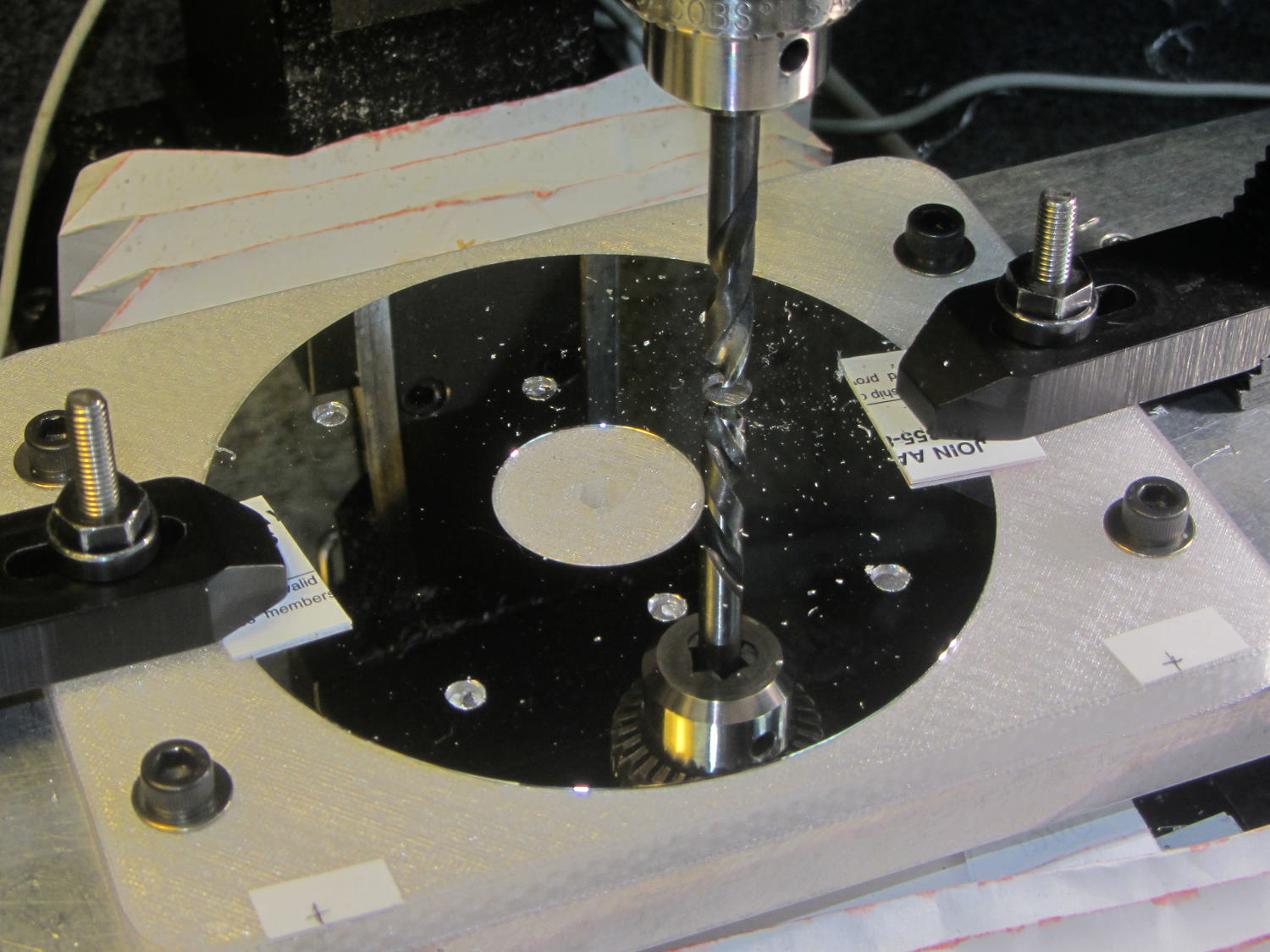
    You’ll recall the LED atop the 21HB5A tube failed, shortly after replacing the bottom LED and rewiring the ersatz plate lead, which led me to rebuild the whole thing with SK6812 RGBW LEDs. So I printed all the plastic parts again, because the duodecar tube socket’s pin circle can fit into a hard drive platter’s unmodified 25 mm hole, then drilled another platter to suit:

    Duodecar disk drilling
    Duodecar disk drilling

    The hole under the drill fits the 3.5 mm stereo socket for the ersatz plate lead, so it’s bigger than before.

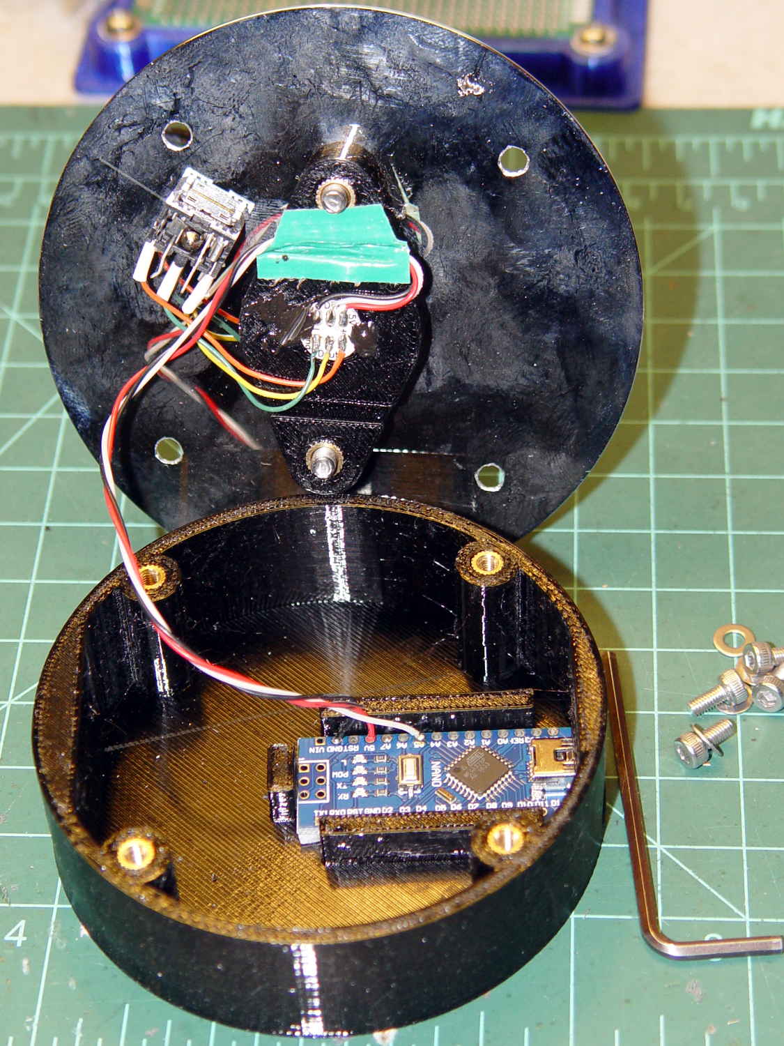
    I’ve switched from Arduino Pro Minis with a separate USB converter to Arduino Nanos with an on-board CH340 USB chip, because the fake FTDI chips on the converters are a continuing aggravation:

    21HB5A base - interior
    21HB5A base – interior

    Adding those wire slots to the sockets definitely helps tidy things up; the wires no longer need a crude cable tie anchoring them to the socket mounting screws.

    I wanted to drive the LEDs from the A7 pin, rather than the A3 pin I’d been using on the Pro Minis, to keep the wires closer together, but it turns out that A6 and A7 can’t become digital output pins. So I used A5, although I may come to regret the backward incompatibility.

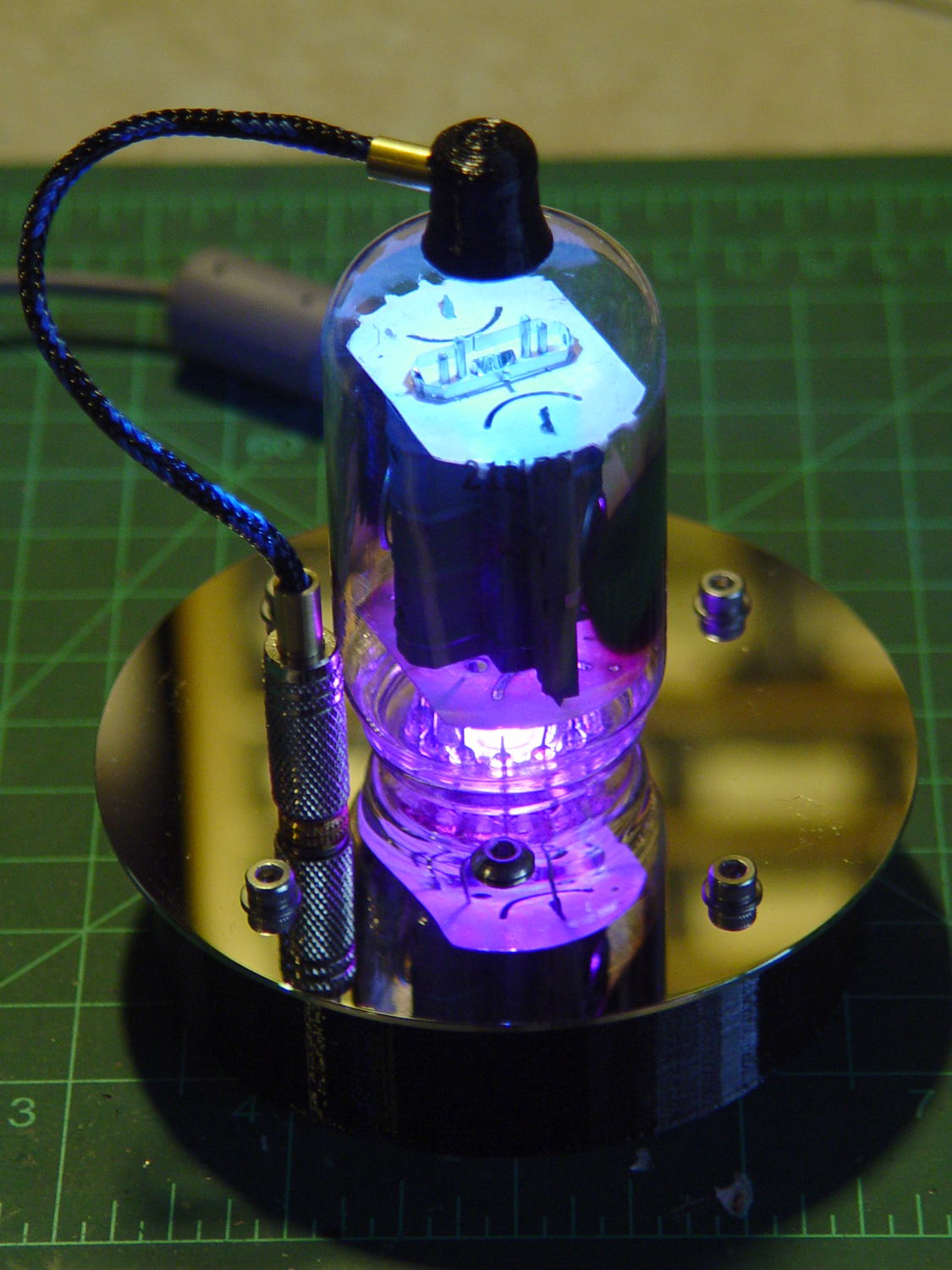
    In any event, the 21HB5A tube looks spiffy with its new LEDs in full effect:

    21HB5A with RBGBW LEDs - cyan violet phase
    21HB5A with RBGBW LEDs – cyan violet phase

    I dialed the white LED PWM down to 32, making the colors somewhat pastel, rather than washed-out.

    The Arduino source code as a GitHub Gist:

    // Neopixel mood lighting for vacuum tubes
    // Ed Nisley – KE4ANU – June 2016
    // September 2016 – Add Morse library and blinkiness
    // October 2016 – Set random colors at cycle end
    // March 2017 – RGBW SK6812 LEDs
    #include <Adafruit_NeoPixel.h>
    #include <morse.h>
    #include <Entropy.h>
    //———-
    // Pin assignments
    const byte PIN_NEO = A5; // DO – data out to first Neopixel
    const byte PIN_HEARTBEAT = 13; // DO – Arduino LED
    #define PIN_MORSE 12
    //———-
    // Constants
    // number of pixels
    #define PIXELS 2
    // index of the Morse output pixel and how fast it sends
    boolean Send_Morse = false;
    #define PIXEL_MORSE (PIXELS – 1)
    #define MORSE_WPM 10
    // lag between adjacent pixel, degrees of slowest period
    #define PIXELPHASE 45
    // update LEDs only this many ms apart (minus loop() overhead)
    #define UPDATEINTERVAL 50ul
    #define UPDATEMS (UPDATEINTERVAL – 1ul)
    // number of steps per cycle, before applying prime factors
    #define RESOLUTION 500
    //———-
    // Globals
    // instantiate the Neopixel buffer array
    Adafruit_NeoPixel strip = Adafruit_NeoPixel(PIXELS, PIN_NEO, NEO_GRBW + NEO_KHZ800);
    uint32_t FullWhite = strip.Color(255,255,255,255);
    uint32_t FullOff = strip.Color(0,0,0,0);
    uint32_t MorseColor;
    struct pixcolor_t {
    unsigned int Prime;
    unsigned int NumSteps;
    unsigned int Step;
    float StepSize;
    float Phase;
    byte MaxPWM;
    };
    unsigned int PlatterSteps;
    byte PrimeList[] = {3,5,7,13,19,29};
    // colors in each LED
    enum pixcolors {RED, GREEN, BLUE, WHITE, PIXELSIZE};
    struct pixcolor_t Pixels[PIXELSIZE]; // all the data for each pixel color intensity
    uint32_t UniColor;
    unsigned long MillisNow;
    unsigned long MillisThen;
    // Morse code
    char * MorseText = " cq cq cq de ke4znu";
    LEDMorseSender Morse(PIN_MORSE, (float)MORSE_WPM);
    uint8_t PrevMorse, ThisMorse;
    //– Figure PWM based on current state
    byte StepColor(byte Color, float Phi) {
    byte Value;
    Value = (Pixels[Color].MaxPWM / 2.0) * (1.0 + sin(Pixels[Color].Step * Pixels[Color].StepSize + Phi));
    // Value = (Value) ? Value : Pixels[Color].MaxPWM; // flash at dimmest points for debug
    return Value;
    }
    //– Select three unique primes for the color generator function
    // Then compute all the step parameters based on those values
    void SetColorGenerators(void) {
    Pixels[RED].Prime = PrimeList[random(sizeof(PrimeList))];
    do {
    Pixels[GREEN].Prime = PrimeList[random(sizeof(PrimeList))];
    } while (Pixels[RED].Prime == Pixels[GREEN].Prime);
    do {
    Pixels[BLUE].Prime = PrimeList[random(sizeof(PrimeList))];
    } while (Pixels[BLUE].Prime == Pixels[RED].Prime ||
    Pixels[BLUE].Prime == Pixels[GREEN].Prime);
    do {
    Pixels[WHITE].Prime = PrimeList[random(sizeof(PrimeList))];
    } while (Pixels[WHITE].Prime == Pixels[RED].Prime ||
    Pixels[WHITE].Prime == Pixels[GREEN].Prime ||
    Pixels[WHITE].Prime == Pixels[BLUE].Prime);
    printf("Primes: %d %d %d %d\r\n",Pixels[RED].Prime,Pixels[GREEN].Prime,Pixels[BLUE].Prime,Pixels[WHITE].Prime);
    Pixels[RED].MaxPWM = 255;
    Pixels[GREEN].MaxPWM = 255;
    Pixels[BLUE].MaxPWM = 255;
    Pixels[WHITE].MaxPWM = 32;
    unsigned int PhaseSteps = (unsigned int) ((PIXELPHASE / 360.0) *
    RESOLUTION * (unsigned int) max(max(max(Pixels[RED].Prime,Pixels[GREEN].Prime),Pixels[BLUE].Prime),Pixels[WHITE].Prime));
    printf("Pixel phase offset: %d deg = %d steps\r\n",(int)PIXELPHASE,PhaseSteps);
    for (byte c=0; c < PIXELSIZE; c++) {
    Pixels[c].NumSteps = RESOLUTION * Pixels[c].Prime; // steps per cycle
    Pixels[c].StepSize = TWO_PI / Pixels[c].NumSteps; // radians per step
    Pixels[c].Step = random(Pixels[c].NumSteps); // current step
    Pixels[c].Phase = PhaseSteps * Pixels[c].StepSize;; // phase in radians for this color
    printf(" c: %d Steps: %d Init: %d Phase: %d deg",c,Pixels[c].NumSteps,Pixels[c].Step,(int)(Pixels[c].Phase * 360.0 / TWO_PI));
    printf(" PWM: %d\r\n",Pixels[c].MaxPWM);
    }
    }
    //– Helper routine for printf()
    int s_putc(char c, FILE *t) {
    Serial.write(c);
    }
    //——————
    // Set the mood
    void setup() {
    pinMode(PIN_HEARTBEAT,OUTPUT);
    digitalWrite(PIN_HEARTBEAT,LOW); // show we arrived
    Serial.begin(57600);
    fdevopen(&s_putc,0); // set up serial output for printf()
    printf("Vacuum Tube Mood Light – RGBW\r\nEd Nisley – KE4ZNU – March 2017\r\n");
    Entropy.initialize(); // start up entropy collector
    // set up pixels
    strip.begin();
    strip.show();
    // lamp test: a brilliant white flash
    printf("Lamp test: flash white\r\n");
    for (byte i=0; i<5 ; i++) {
    for (int j=0; j < strip.numPixels(); j++) { // fill LEDs with white
    strip.setPixelColor(j,FullWhite);
    }
    strip.show();
    delay(500);
    for (int j=0; j < strip.numPixels(); j++) { // fill LEDs with black
    strip.setPixelColor(j,FullOff);
    }
    strip.show();
    delay(500);
    }
    // get an actual random number
    uint32_t rn = Entropy.random();
    printf("Random seed: %08lx\r\n",rn);
    randomSeed(rn);
    // set up the color generators
    SetColorGenerators();
    // set up Morse generator
    Morse.setup();
    Morse.setMessage(String(MorseText));
    MorseColor = strip.Color(255,random(32,64),random(16),0);
    PrevMorse = ThisMorse = digitalRead(PIN_MORSE);
    printf("Morse enabled: %d at %d wpm color: %08lx\n [%s]\r\n",Send_Morse,MORSE_WPM,MorseColor,MorseText);
    MillisNow = MillisThen = millis();
    }
    //——————
    // Run the mood
    void loop() {
    if (!Morse.continueSending()) {
    printf("Restarting Morse message\r\n");
    Morse.startSending();
    }
    ThisMorse = digitalRead(PIN_MORSE);
    MillisNow = millis();
    if (((MillisNow – MillisThen) >= UPDATEMS) || // time for color change?
    (PrevMorse != ThisMorse)) { // Morse output bit changed?
    digitalWrite(PIN_HEARTBEAT,HIGH);
    if (Send_Morse && ThisMorse) { // if Morse output high, overlay flash
    strip.setPixelColor(PIXEL_MORSE,MorseColor);
    }
    PrevMorse = ThisMorse;
    strip.show(); // send out precomputed colors
    boolean CycleRun = false; // check to see if all cycles have ended
    for (byte c=0; c < PIXELSIZE; c++) { // compute next increment for each color
    if (++Pixels[c].Step >= Pixels[c].NumSteps) {
    Pixels[c].Step = 0;
    printf("Cycle %d steps %d at %8ld delta %ld ms\r\n",c,Pixels[c].NumSteps,MillisNow,(MillisNow – MillisThen));
    }
    else {
    CycleRun = true; // this color is still cycling
    }
    }
    // If all cycles have completed, reset the color generators
    if (!CycleRun) {
    printf("All cycles ended: setting new color generator values\r\n");
    SetColorGenerators();
    }
    for (int i=0; i < strip.numPixels(); i++) { // for each pixel
    byte Value[PIXELSIZE];
    for (byte c=0; c < PIXELSIZE; c++) { // … for each color
    Value[c] = (Pixels[c].MaxPWM / 2.0) * (1.0 + sin(Pixels[c].Step * Pixels[c].StepSize – i*Pixels[c].Phase));
    }
    UniColor = strip.Color(Value[RED],Value[GREEN],Value[BLUE],Value[WHITE]);
    strip.setPixelColor(i,UniColor);
    }
    MillisThen = MillisNow;
    digitalWrite(PIN_HEARTBEAT,LOW);
    }
    }
    view raw TubeMorse.ino hosted with ❤ by GitHub
  • Check Your Zero

    A recent OpenSCAD mailing list discussion started with an observation that the dimensions of printed parts were wildly different from the numeric values used in the OpenSCAD program that created the STL. Various folks suggested possible errors, examined the source and STL files to no avail, and were generally baffled.

    Finally, a photo conclusively demonstrating the problem arrived:

    Caliper - digital vs. analog scale
    Caliper – digital vs. analog scale

    Note the difference between the digital readout and the analog scale printed on the body.

    Turns out it’s his first digital caliper: he simply didn’t realize you must close the jaws and press the ZERO button before making any measurements.

    We’ve all been that guy. Right?

    FWIW, our Larval Engineer can probably still hear me intoning “Check your zero” every time she picks up a caliper or turns on a multimeter. Perhaps she’ll think fondly of me, some day. [grin]

  • Bandsaw Worklight

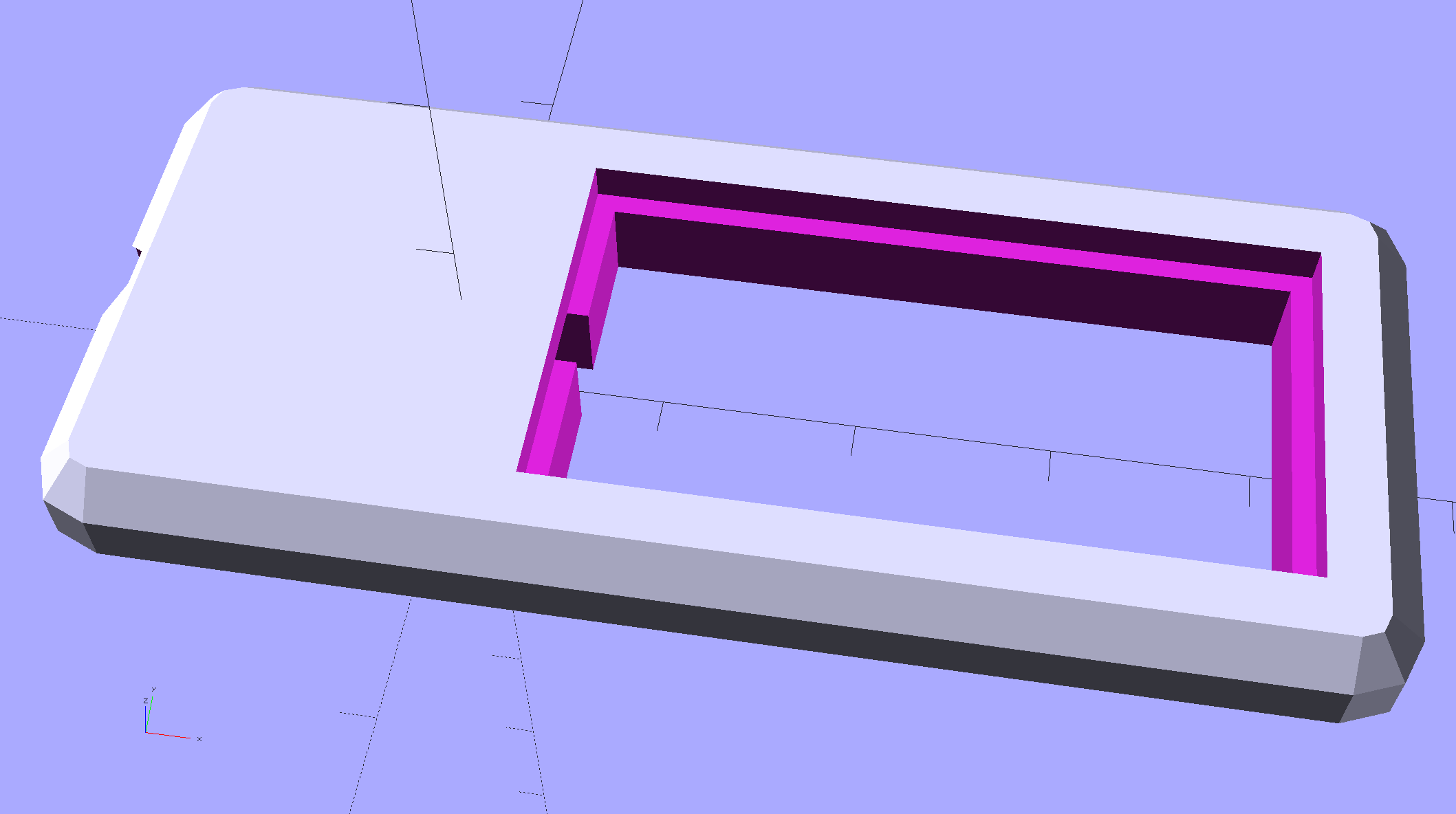
    Having hacked back the end of the USB gooseneck extension, a tweak of the COB LED heatsink mount for my desk lamp produces a smaller version for a 1.8 W LED:

    Chip On Board Heatsink Mount - Bandsaw Lamp - solid model
    Chip On Board Heatsink Mount – Bandsaw Lamp – solid model

    That fits half of a random heatsink, bandsawed just to the far side of the middle fin and milled flat.

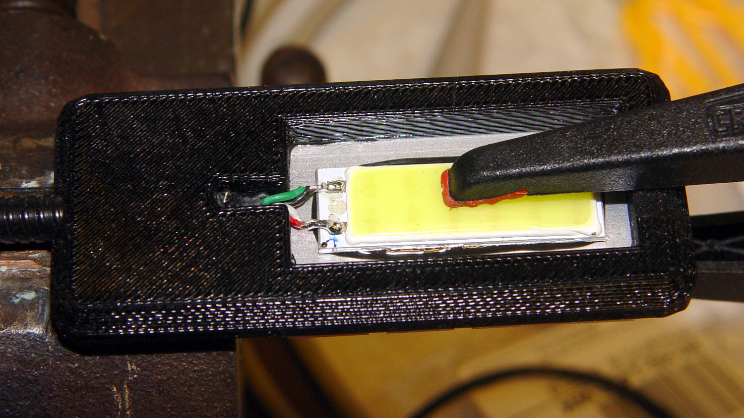
    Ream out the 5 mm hole with a #8 drill for a snug fit around the gooseneck, jam gooseneck in place, dab epoxy on the corners of the recess, mash the heatsink in place, solder wires to LED, smear epoxy on the aluminum backplate, clamp while curing:

    USB Gooseneck - LED assembly
    USB Gooseneck – LED assembly

    And it looks pretty good, if I do say so myself:

    USB Gooseneck - on bandsaw
    USB Gooseneck – on bandsaw

    The hook-n-loop tape holding the cable to the bandsaw gotta go, but should suffice until I conjure a better mount.

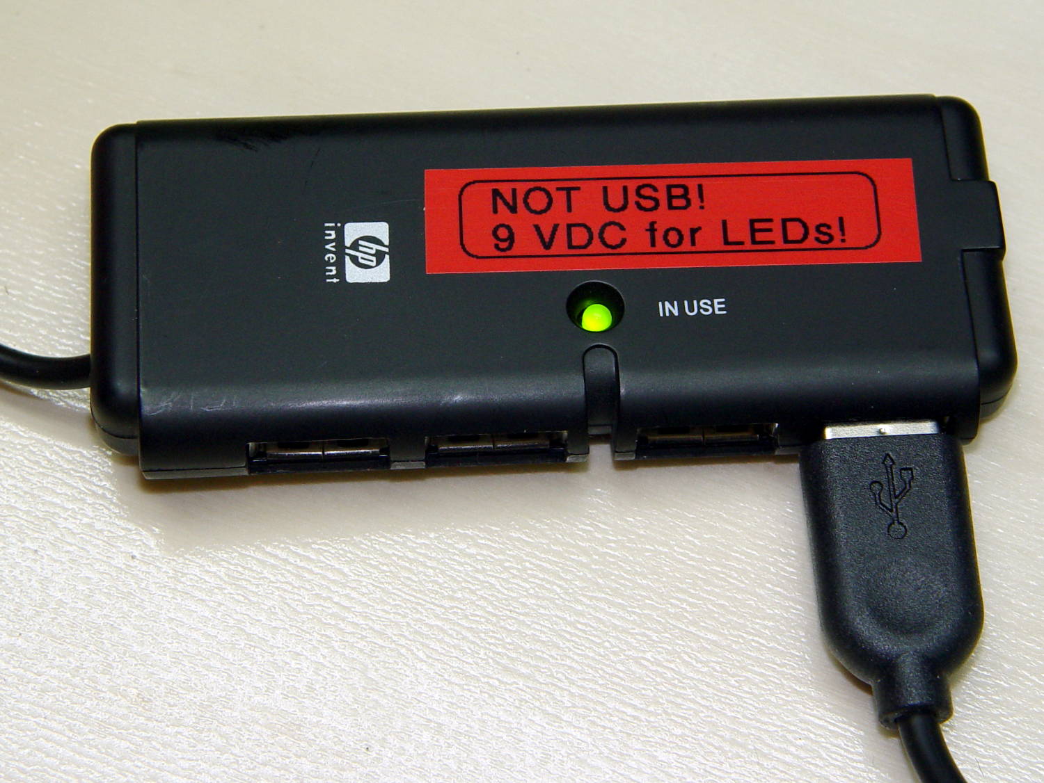
    The alert reader may wonder how a 9 V COB LED runs from a 5 V USB cable with nary a trace of a voltage booster to be seen. Well, that’s not really a USB cable any more; I paralleled the red+white and black+green wires for lower resistance, then hacked a 9 VDC power supply into an old USB hub:

    Hacked USB hub - PCB mods
    Hacked USB hub – PCB mods

    I ripped out the upstream USB plug, hotwired the 9 V supply where the 5 V USB wires used to be, soldered jumpers on the downstream sockets to short the outer two pin pairs together, razor-knifed the power leads going into the epoxy-blobbed USB controller, and declared victory:

    Hacked USB hub - in use
    Hacked USB hub – in use

    Admittedly, that “In Use” LED runs a bit brighter now.

    I have a few other tools on that bench in need of LED lights; when I build ’em, they can all plug into this hub. No reason to invent new connectors & cables & all that. It may need a power switch.

    Turns your stomach, eh?

    The OpenSCAD source code as a GitHub Gist:

    // Chip-on-board LED light heatsink mount for desk lamp
    // Ed Nisley KE4ZNU December 2015
    // February 2017 – rectangular COB, smaller heatsink
    Layout = "Show"; // Show Build
    //- Extrusion parameters must match reality!
    ThreadThick = 0.25;
    ThreadWidth = 0.40;
    HoleWindage = 0.2;
    Protrusion = 0.1; // make holes end cleanly
    inch = 25.4;
    function IntegerMultiple(Size,Unit) = Unit * ceil(Size / Unit);
    //———————-
    // Dimensions
    ID = 0; // for round things
    OD = 1;
    LENGTH = 2;
    Gooseneck = [3.0,5.0,15.0]; // anchor for end of gooseneck
    COB = [30.0,11.0,2.5]; // Chip-on-board LED module
    Heatsink = [37.1,19.2,10.0]; // overall
    HeatsinkBase = 2.0; // solid base below fins
    HSLip = 1.0; // width of lip under heatsink
    BaseMargin = 2*2*ThreadWidth;
    BaseRadius = 3*ThreadThick + Gooseneck[OD]/2; // defines slab thickness
    BaseSides = 2*4;
    Base = [(Gooseneck[LENGTH] + Gooseneck[OD] + Heatsink[0] + 2*BaseRadius + BaseMargin),
    (Heatsink[1] + 2*BaseRadius + 2*BaseMargin),
    2*BaseRadius];
    echo(str("Slab thickness: ",Base[2]));
    //———————-
    // Useful routines
    module PolyCyl(Dia,Height,ForceSides=0) { // based on nophead's polyholes
    Sides = (ForceSides != 0) ? ForceSides : (ceil(Dia) + 2);
    FixDia = Dia / cos(180/Sides);
    cylinder(r=(FixDia + HoleWindage)/2,
    h=Height,
    $fn=Sides);
    }
    //– Lamp heatsink mount
    module Lamp() {
    difference() {
    translate([(Base[0]/2 – BaseRadius – Gooseneck[LENGTH]),0,0])
    hull()
    for (i=[-1,1], j=[-1,1])
    translate([i*(Base[0]/2 – BaseRadius),j*(Base[1]/2 – BaseRadius),Base[2]/2])
    sphere(r=BaseRadius/cos(180/BaseSides),$fn=BaseSides);
    translate([(Heatsink[0]/2 + Gooseneck[OD]), // main heatsink recess
    0,
    (Base[2] + Heatsink[2]/2 – HeatsinkBase)])
    cube((Heatsink + [HoleWindage,HoleWindage,0.0]),center=true);
    translate([(Heatsink[0]/2 + Gooseneck[OD]),0,HeatsinkBase]) // lower lip to shade lamp module
    scale([1,1,2])
    cube(Heatsink – [2*HSLip,2*HSLip,0],center=true);
    translate([0,0,Base[2]/2]) // goooseneck insertion
    rotate([0,-90,0]) rotate(180/8)
    PolyCyl(Gooseneck[OD],Base[0],8);
    translate([0,0,Base[2]/2 + Gooseneck[ID]/2]) // wire exit
    rotate([180,0,0])
    PolyCyl(Gooseneck[ID],Base[2],6);
    translate([Gooseneck[OD],0,(Base[2] – HeatsinkBase – Protrusion)/2]) // wire slot
    rotate([180,0,0])
    cube([2*Gooseneck[OD],Gooseneck[ID],(Base[2] – HeatsinkBase + Protrusion)],center=true);
    }
    }
    //———————-
    // Build it
    if (Layout == "Show") {
    Lamp();
    }
    if (Layout == "Build") {
    }


  • Pot Lid Repair

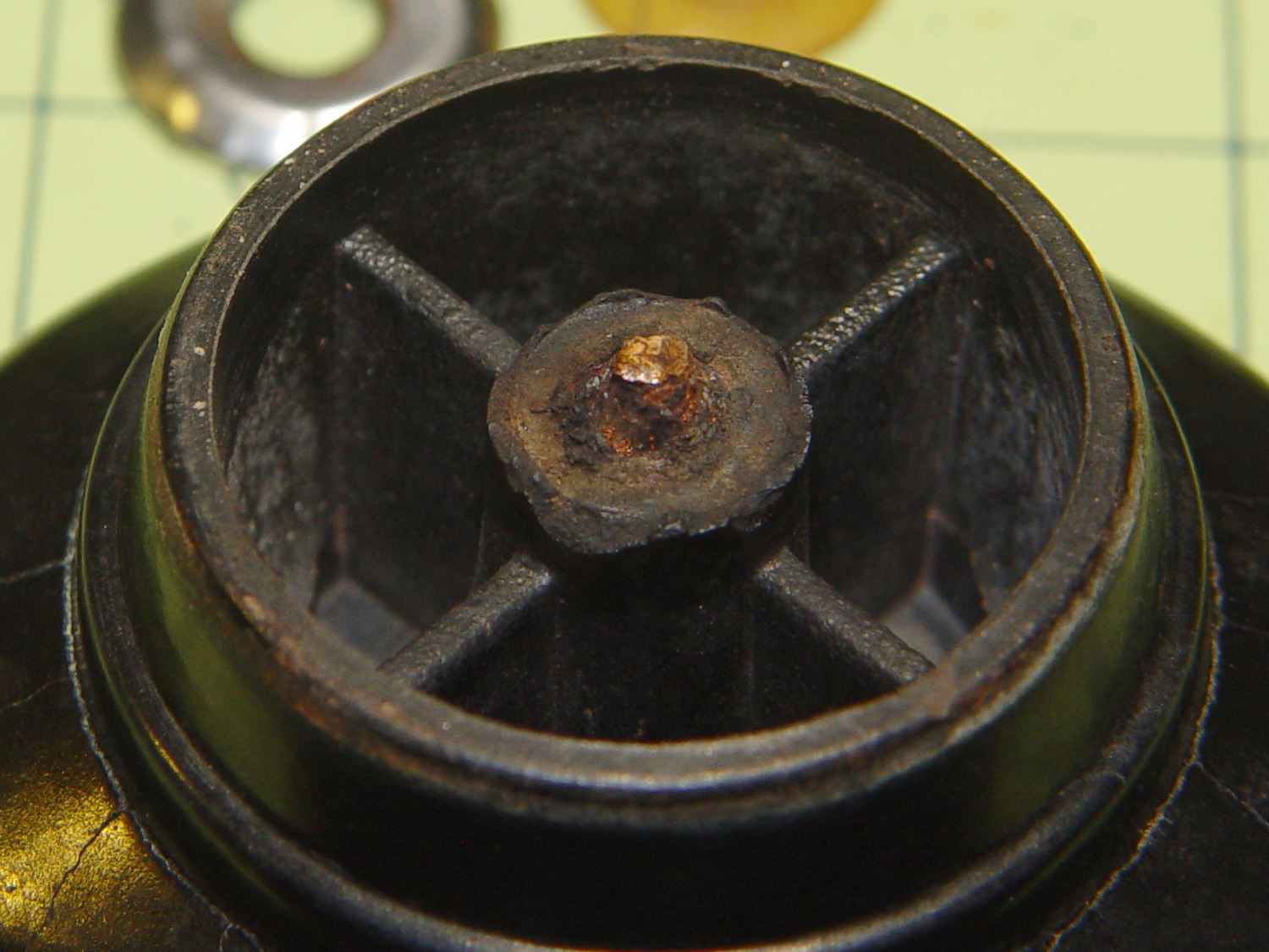
    For reasons not relevant here, we (temporarily) have a set of pots with glass lids. One of lids had a remarkable amount of crud between the glass and the trim ring under the knob, which turned out to be corrosion falling off the screw. Trying to remove the screw produced the expected result:

    CKC Pot Lid - broken screw in handle
    CKC Pot Lid – broken screw in handle

    For whatever reason, they used an ordinary, not stainless, steel screw:

    CKC Pot Lid - corroded screw
    CKC Pot Lid – corroded screw

    I figured I could mill the stub flat, drill out the remainder, install a new insert, and be done with it. The knob has a convex surface and, even though this looked stupid, I tried clamping it atop a wood pad:

    CKC Pot Lid - precarious clamping
    CKC Pot Lid – precarious clamping

    Two gentle cutter passes convinced me it was, in fact, a lethally stupid setup.

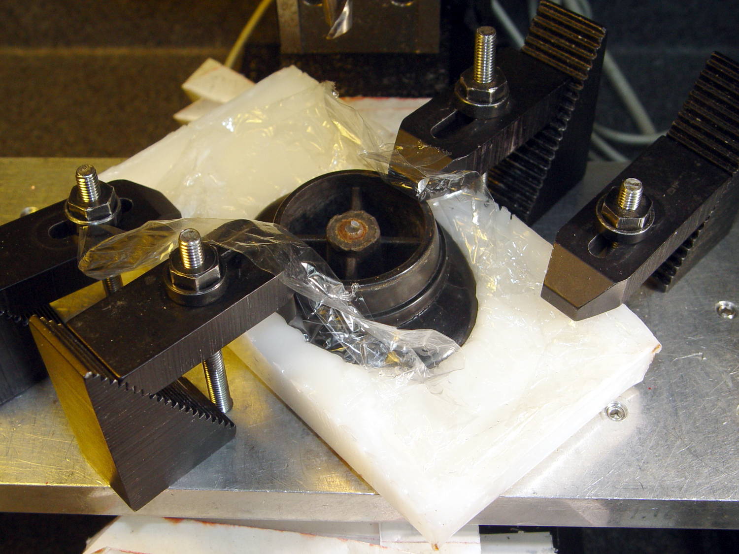
    Soooo, I poured some ShapeLock pellets into a defunct (and very small) loaf pan, melted them in near-boiling water, and pressed the knob into the middle, atop some stretchy film to prevent gluing the knob in place:

    CKC Pot Lid - ShapeLock bedding
    CKC Pot Lid – ShapeLock bedding

    That’s eyeballometrically level, which is good enough, and the knob sits mechanically locked into the room-temperature plastic slab. Clamping everything down again makes for a much more secure operation:

    CKC Pot Lid - clamped ShapeLock fixture
    CKC Pot Lid – clamped ShapeLock fixture

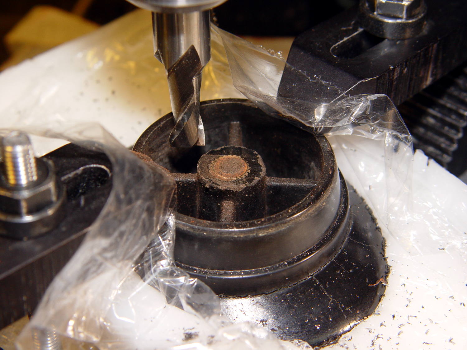
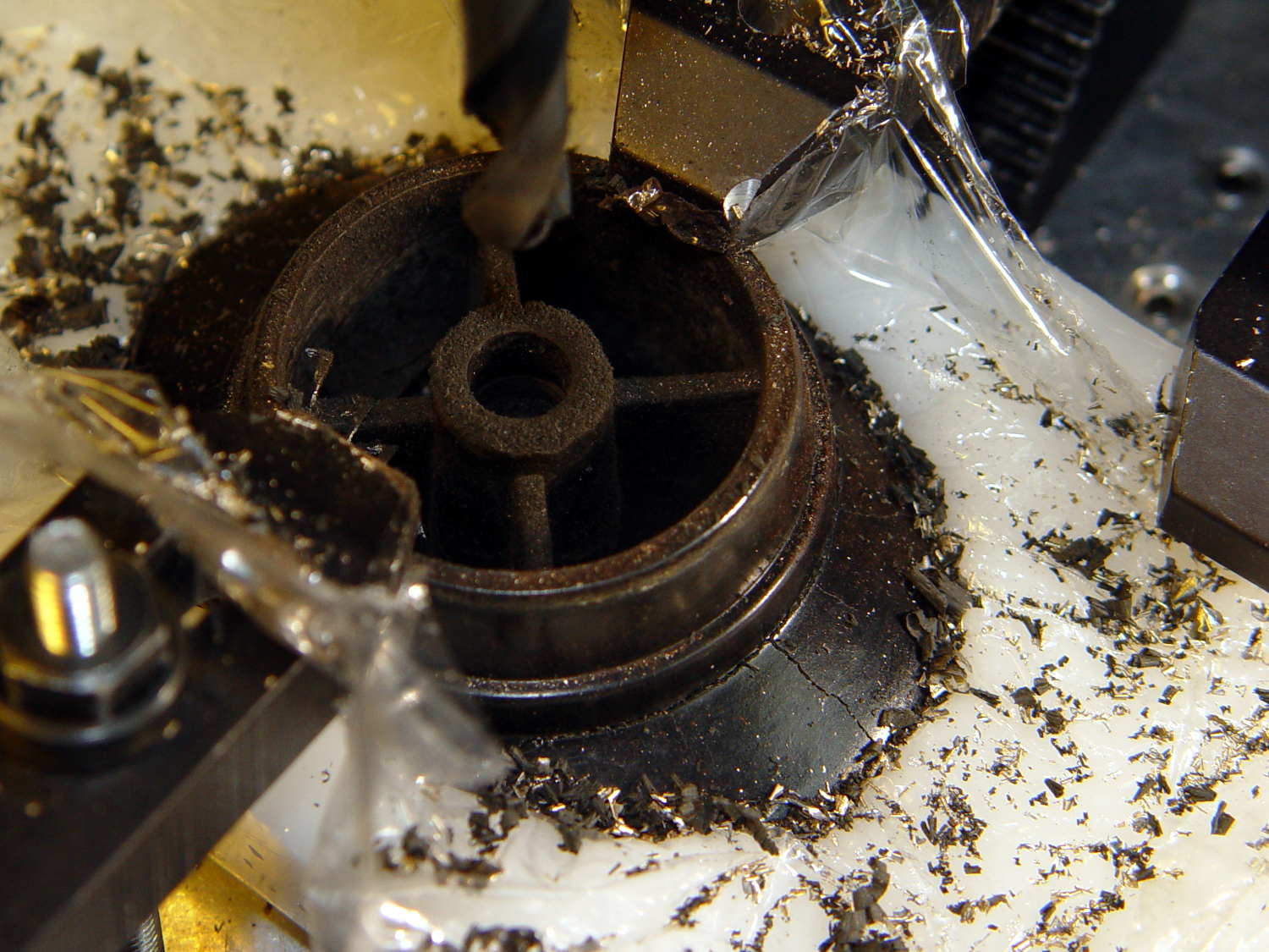
    A few minutes of manual milling exposes the original brass insert molded into the knob, with the steel screw firmly corroded in the middle:

    CKC Pot Lid - screw stub milled flat
    CKC Pot Lid – screw stub milled flat

    Center-drill, drill small-medium-large, and eventually the entire insert vanishes in  a maelstrom of chips and dust:

    CKC Pot Lid - OEM insert removed
    CKC Pot Lid – OEM insert removed

    Run a 10-32 stud into an insert, grab in drill chuck, dab JB Kwik around the knurls, press in place while everything’s still aligned in the Sherline, pause for curing, re-melt the ShapeLock, and the insert looks like it grew there:

    CKC Pot Lid - new insert installed
    CKC Pot Lid – new insert installed

    Wonder to tell, a 1 inch 10-32 screw fit perfectly through the pot lid into the knob, with a dab of low-strength Loctite securing it. Reassemble everything in reverse order, and it’s all good:

    CKC Pot Lid - repaired knob
    CKC Pot Lid – repaired knob

    Well, apart from those cracks. I decided I will not borrow trouble from the future: we’ll let those problems surface on their own and, if I’m still in the loop, I can fix them.

  • TCRT5000 Proximity Sensor Mount

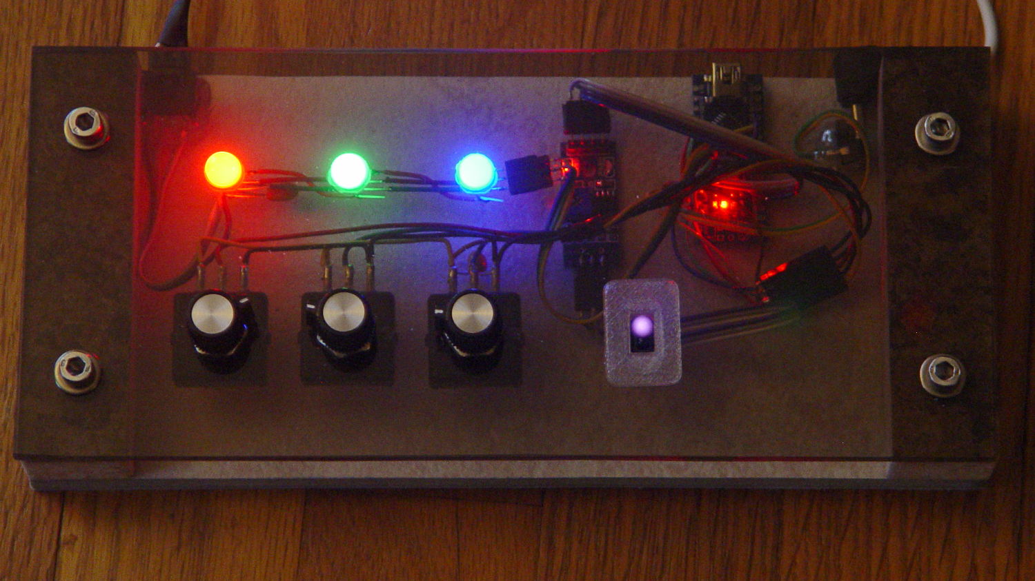
    Having a few TCRT5000 proximity sensors lying around, I used one for the Color Mixer so folks could just wave a finger to flip the LED colors, rather than pound relentlessly on the top plate:

    Color mixer - controls
    Color mixer – controls

    The stem fits into a slot made with a 3/8 inch end mill:

    Prox Sensor Bezel - Slic3r preview
    Prox Sensor Bezel – Slic3r preview

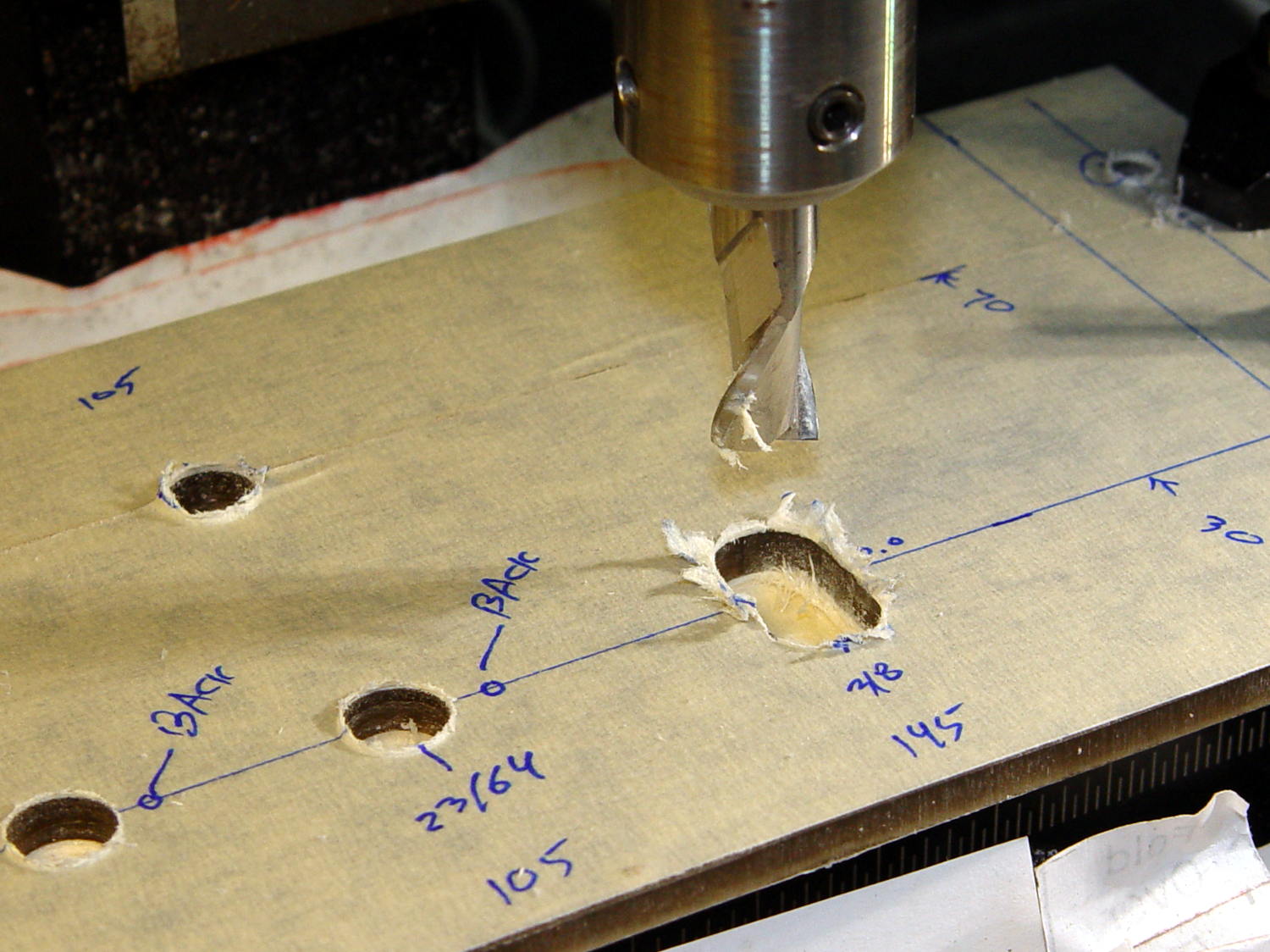
    You move the cutter by the length of the sensor (10.0 mm will work) to make the slot. In practical terms, drill a hole at the midpoint, insert the cutter, then move ±5.0 mm from the center:

    Prox sensor panel cut
    Prox sensor panel cut

    A bead of epoxy around the stem on the bottom of the panel should hold it in place forevermore.

    The rectangular inner hole came out a tight push fit for the TCRT5000 sensor, so I didn’t bother gluing it in place and, surprisingly, it survived the day unscathed!

    The OpenSCAD source code as a GitHub Gist:

    // TCRT5000 Proximity switch sensor mount
    // Ed Nisley KE4ZNU – October 2016
    Layout = "Build"; // Show Build
    //- Extrusion parameters must match reality!
    ThreadThick = 0.25;
    ThreadWidth = 0.40;
    HoleWindage = 0.2;
    Protrusion = 0.1; // make holes end cleanly
    inch = 25.4;
    function IntegerMultiple(Size,Unit) = Unit * ceil(Size / Unit);
    //———————-
    // Dimensions
    Sensor = [5.9,10.0,7.0];
    SensorHoleCutter = 3/8 * inch;
    echo(str("Cutter dia: ",SensorHoleCutter," mm"));
    echo(str("Cutter motion: ",Sensor[1]," mm"));
    PanelThick = 5.0;
    StemLength = PanelThick + 6*ThreadThick;
    FlangeThick = 3 * ThreadThick;
    //———————-
    // Flange model
    module ProxFlange() {
    difference() {
    union() {
    linear_extrude(height=FlangeThick)
    hull()
    for (i=[-1,1], j=[-1,1])
    translate([i*Sensor[0],j*Sensor[1]])
    circle(r=Sensor[0]/2,$fn=8*4);
    translate([0,0,-StemLength])
    linear_extrude(height=StemLength)
    hull()
    for (j=[-1,1])
    translate([0,j*Sensor[1]/2])
    circle(d=SensorHoleCutter,$fn=8*4);
    }
    translate([0,0,-Protrusion])
    cube(Sensor + [HoleWindage,HoleWindage,2*(PanelThick + Protrusion)],center=true);
    }
    }
    //———————-
    // Build it
    if (Layout == "Show")
    ProxFlange();
    if (Layout == "Build")
    translate([0,0,FlangeThick])
    rotate([180,0,0])
    ProxFlange();
  • Vacuum Tube LEDs: 6H6GT Dual Diode

    Having accumulated a set of octal tube base clamps, it’s now a matter of selecting the proper clamp for each tube:

    Octal tube base V-block clamps
    Octal tube base V-block clamps

    The process of shell-drilling the tube base, drilling the hard drive platter, printing a tube socket and case, wiring up the Arduino and base LED, then assembling the whole thing requires a bit of manual labor, assisted by some moderately exotic shop machinery.

    The getter flash atop this small 6H6GT dual diode tube rules out a cap and there’s not enough space for a side light:

    6H6GT - on platter
    6H6GT – on platter

    Fortunately, the base LED completely lights the internal glass:

    6H6GT - purple phase
    6H6GT – purple phase

    The slowly changing color would make a fine night light:

    6H6GT - cyan phase
    6H6GT – cyan phase

    It must be Art!