The Smell of Molten Projects in the Morning

Ed Nisley's Blog: Shop notes, electronics, firmware, machinery, 3D printing, laser cuttery, and curiosities. Contents: 100% human thinking, 0% AI slop.

Tag: Sewing

Fabric arts and machines

  • Juki TL-2010Q: COB LED Light Levels

    The COB LED module claims to run at 12 V and 6 W, so it expects to draw 500 mA. First pass measurements showed 500 mA happened at 11.6 V:

    Juki TL-2010Q COB LED - ballast resistor test
    Juki TL-2010Q COB LED – ballast resistor test

    The 12 VDC supply actually produced 12.1 V at 500 mA, so a 1 Ω 1/2 W resistor should produce the right current:

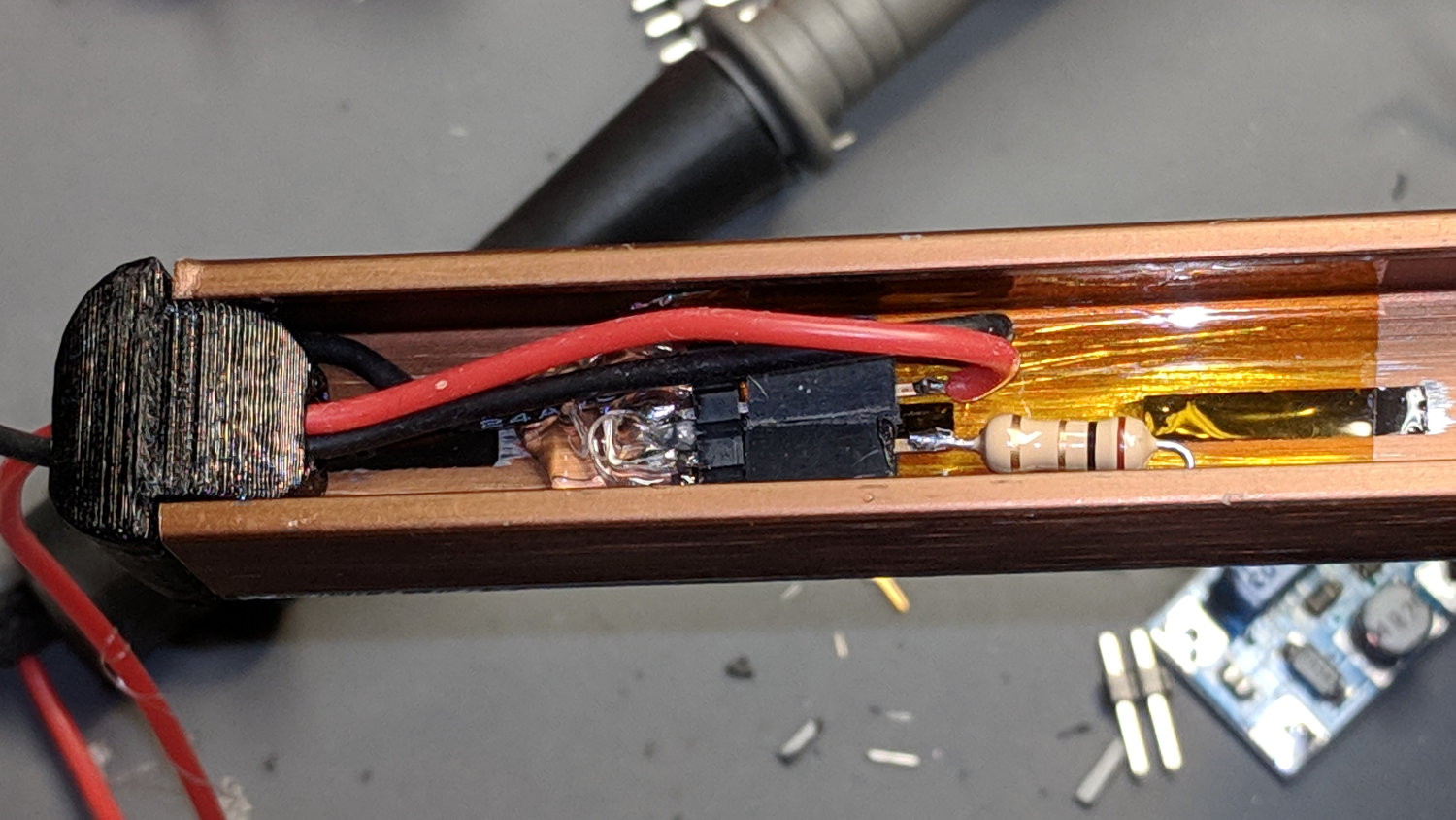
    Juki TL-2010Q COB LED - heatsink endcap - internal connections
    Juki TL-2010Q COB LED – heatsink endcap – internal connections

    Which it did, but the Customer Base judged 6 W to be far too much light. A 2.7 Ω resistor seemed too dim, so we settled on 2.2 Ω:

    Juki TL-2010Q COB LED - 2.2 ohm header
    Juki TL-2010Q COB LED – 2.2 ohm header

    For the record, a 2.2 Ω resistor drops 980 mV and dissipates 440 mW, probably too close to its 500 mW rating. The supply produces 12.2 VDC at 450 mA, so the LEDs run at 11.2 V and dissipate 5 W; the heatsink remains pleasantly warm to the touch.

    The hot melt glue anchoring the pin header won’t win any prizes, but it sticks like glue to the Kapton tape and, in any event, there’s not much to go wrong in there.

    A cardboard cover hides the ugly details:

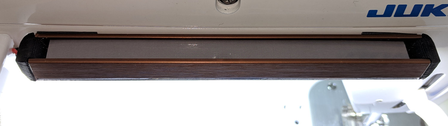
    Juki TL-2010Q COB LED - installed
    Juki TL-2010Q COB LED – installed

    And then It Just Works™:

    Juki TL-2010Q COB LED - installed - rear view
    Juki TL-2010Q COB LED – installed – rear view

    As evidenced by the glove fingertips, she does a lot of sewing and I’m glad I can shed some light on the subject …

  • Juki TL-2010Q: COB LED Power

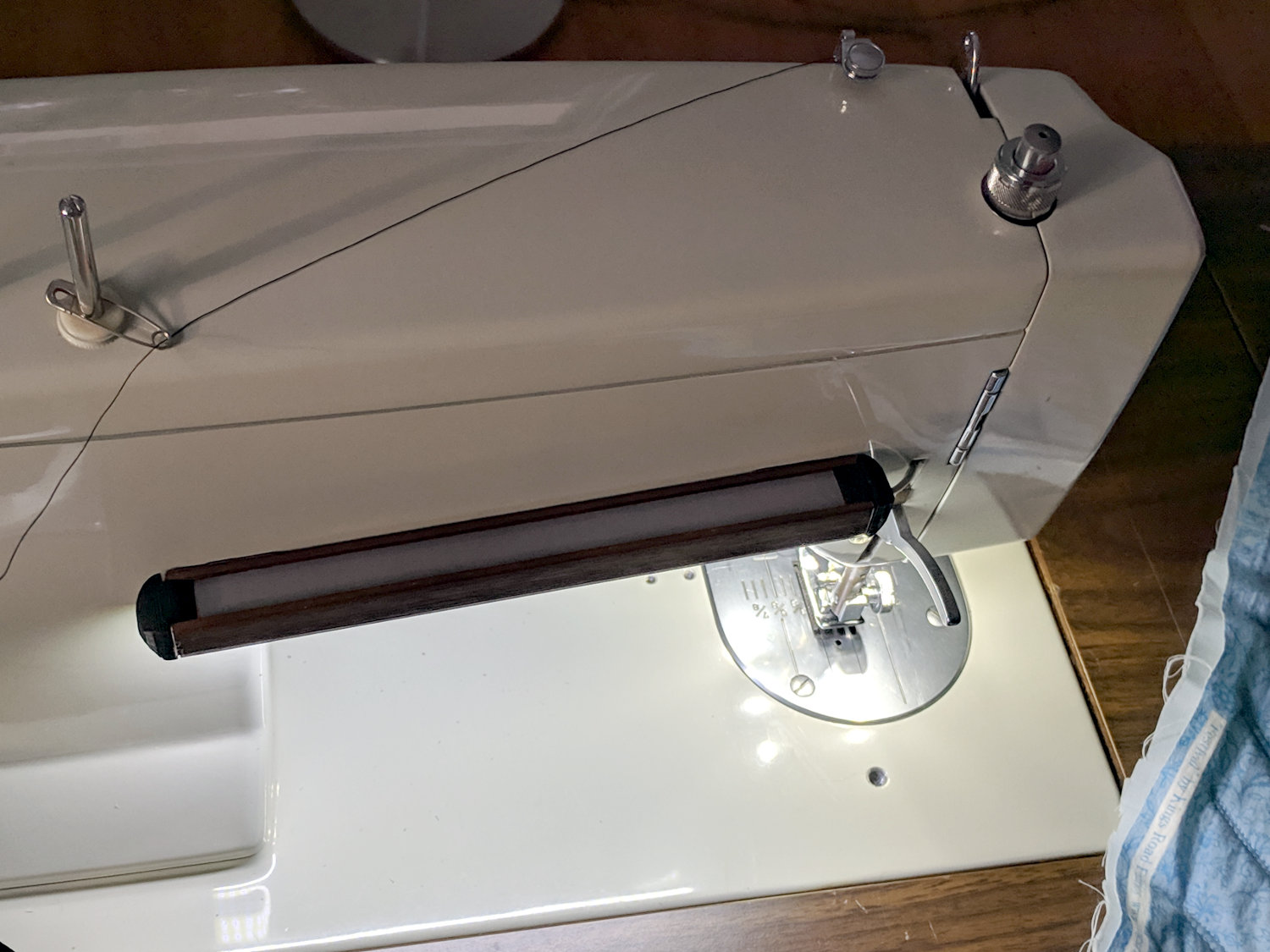
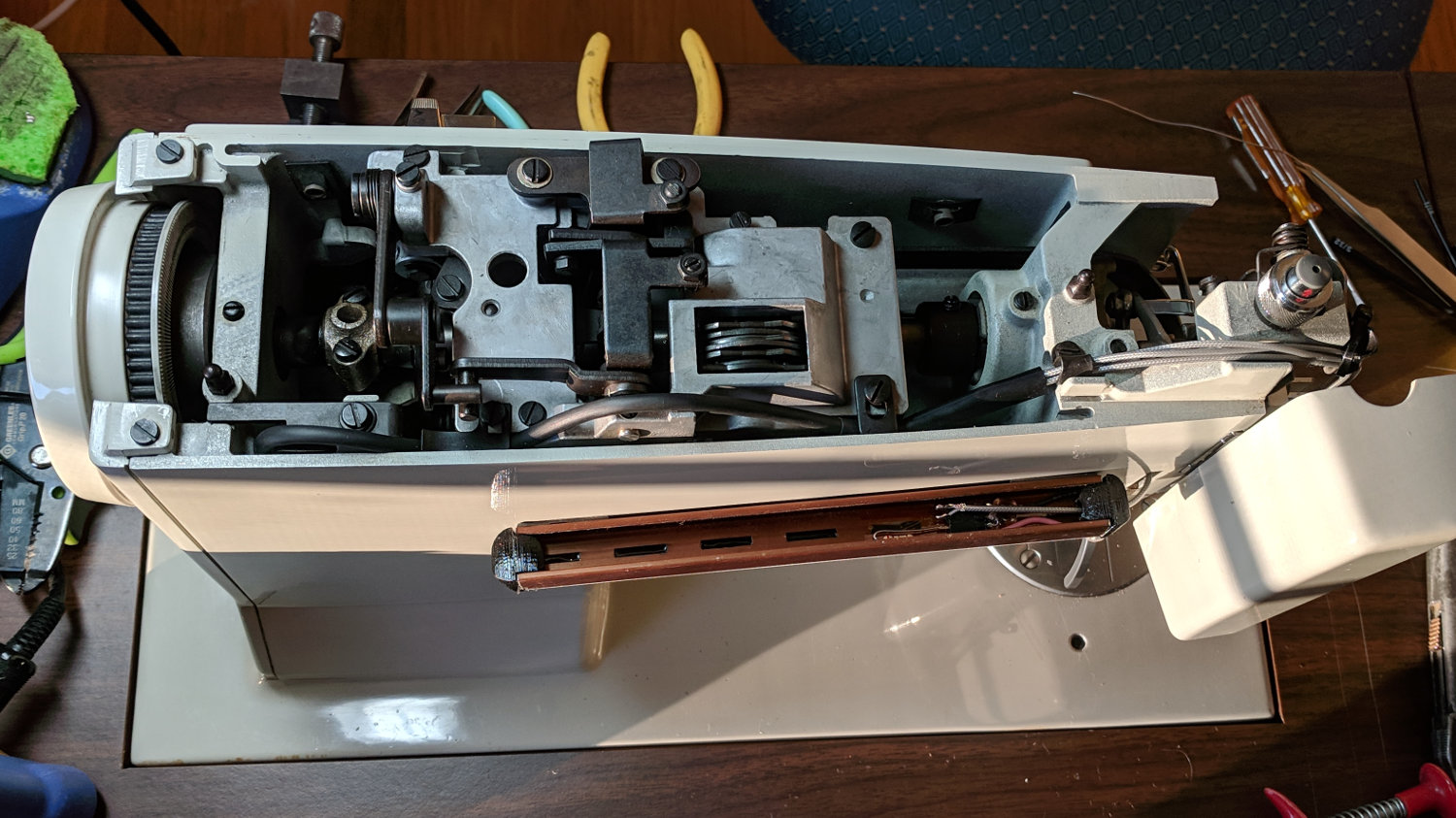
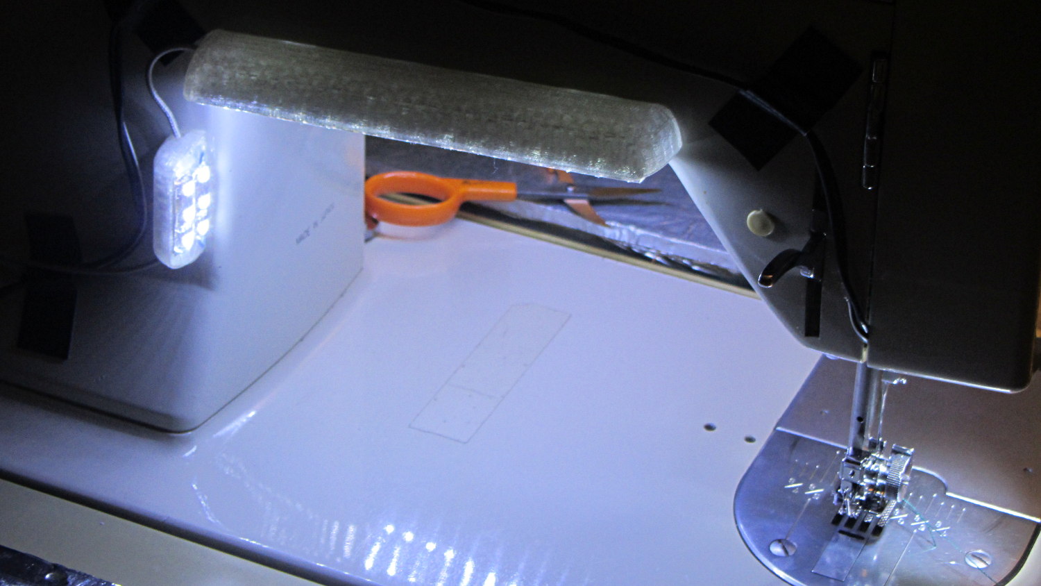
    The wires to my earlier LED lights on Mary’s Kenmore 158 produced one absolute requirement: the Juki TL-2010Q lights must not have any external wiring. Some experimentation showed putting the COB LED module across the rear of the arm, just over the opening, would spill enough light to the front:

    Juki TL-2010Q COB LED - installed - rear view
    Juki TL-2010Q COB LED – installed – rear view

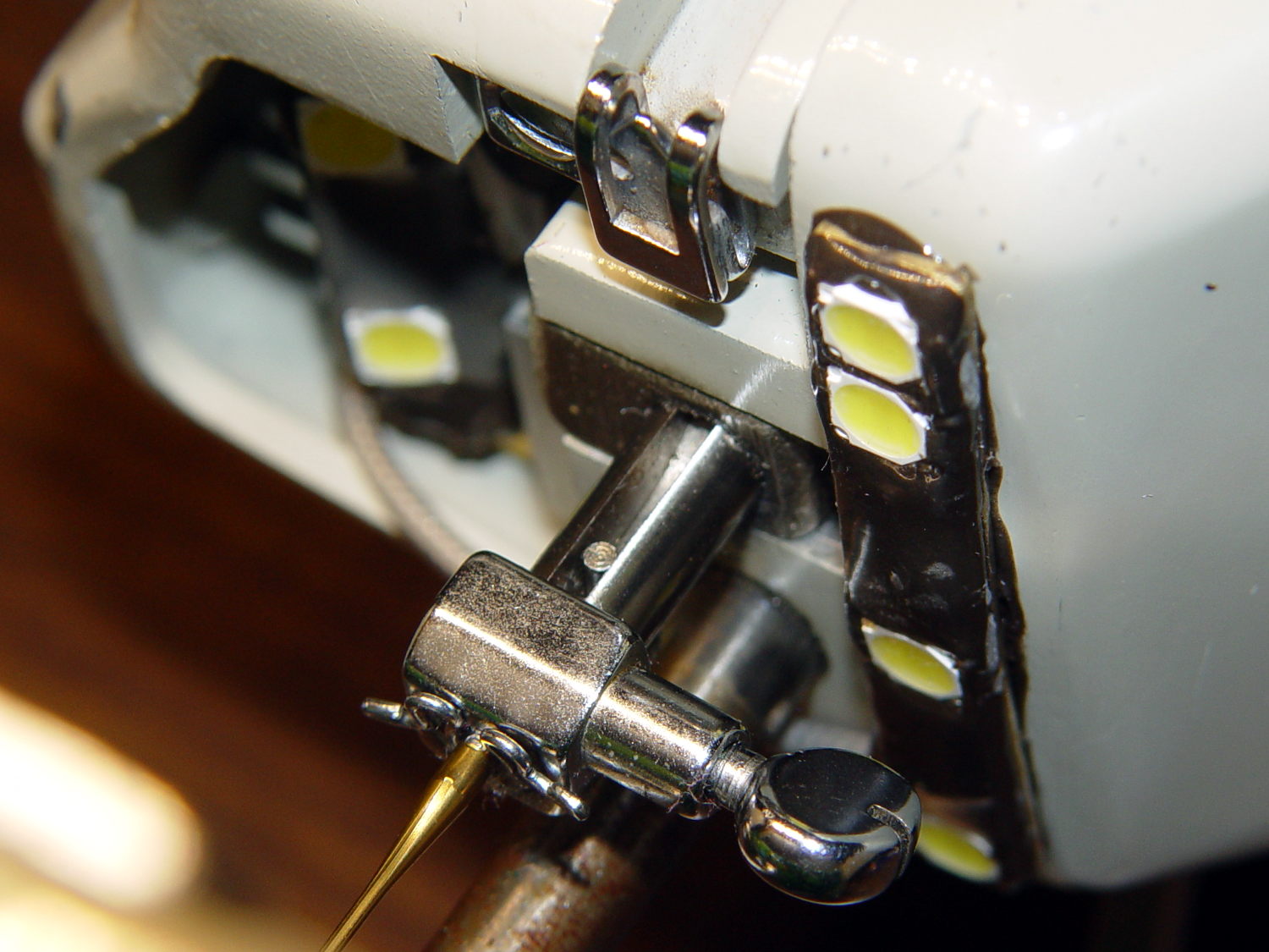
    Juki’s teeny OEM SMD LED in the endcap, just above the far side of the needle, casts a dim glow over her left hand. Although they deem it sufficient, I’ll fix that in the near future.

    The machine’s power supply and drive motor live inside a plastic cover on the rear of the machine, just to the left of where the LED lights will attach to the arm:

    Juki TL-2010Q COB LED - machine power supply
    Juki TL-2010Q COB LED – machine power supply

    For future reference, a detailed look at the PCB:

    Juki TL-2010Q COB LED - machine power supply PCB detail
    Juki TL-2010Q COB LED – machine power supply PCB detail

    The yellow-and-blue pair come from the AC power line switch. The brown-and-blue pair carry +120 VDC from the bridge rectifier (left of their connector) to the motor driver. The white-and-blue pair carry filtered 120 VAC from the PCB to the bulky transformer below the motor.

    I snipped the white-and-blue pair, added Y connections, and threaded the wires through the vent slots to the 12 VDC power supply:

    Juki TL-2010Q COB LED - 12 V supply wiring
    Juki TL-2010Q COB LED – 12 V supply wiring

    If I had to do it again, I’d cut the white-and-blue pair an inch further away from the transformer, so as to move the butt splice connectors around the corner of the frame, rather than across the back of the transformer frame. The flanged screw boss pretty well fills the space left of the transformer and made it difficult to arrange the new connectors.

    The 12 VDC 18 W LED supply attaches to the 120 VAC lines with 1/4 inch quick-disconnects, making it possible, if not easy, to completely remove the cover and LED power supply. You’d install dummy plugs in the vacant QD sockets to keep the AC out of harm’s way.

    There’s just enough space to the right of the PCB enclosure to route the LED wires around-and-down to meet the wire nuts. They’re not the most elegant connectors you’ve ever seen, but wire nuts are impossible to confuse with the QD connectors on the AC line.

    With that in hand, the power supply almost looks like it grew under the spool flange:

    Juki TL-2010Q COB LED - 12 V supply installed
    Juki TL-2010Q COB LED – 12 V supply installed

    In an ideal world, the label would be right-side-up, but ya can’t have everything. The wires had to be where they are, primarily to avoid snagging on fabric passing through the machine.

    The green-and-black PET braid covers the AC wires to make them a little less exposed, but it’s surely unnecessary. I gently singed the braid ends to prevent unraveling.

    The COB LED supply wires emerge through a slot filed in the cover:

    Juki TL-2010Q COB LED - power wires to endcap
    Juki TL-2010Q COB LED – power wires to endcap

    Next step: LED brightness tweakage.

  • Epoxy Joint: Test to Destruction

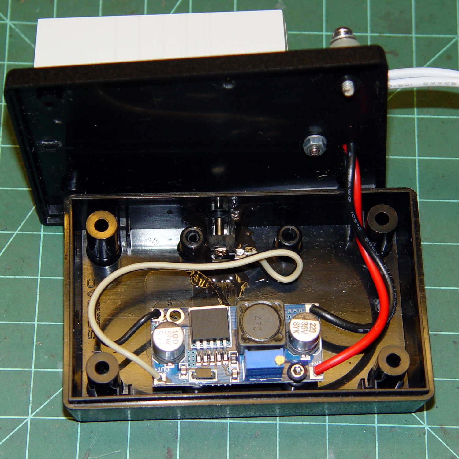
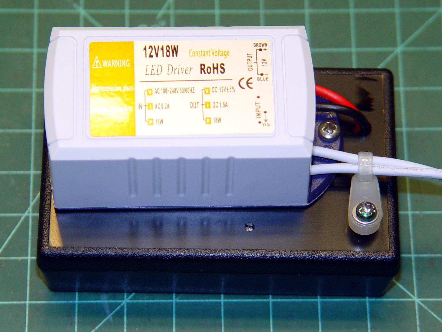
    Some years ago, I put the LED power supply for one of the Kenmore 158 machines atop a plastic project box with an adjustable boost supply inside:

    Needle LEDs power supply - exterior
    Needle LEDs power supply – exterior

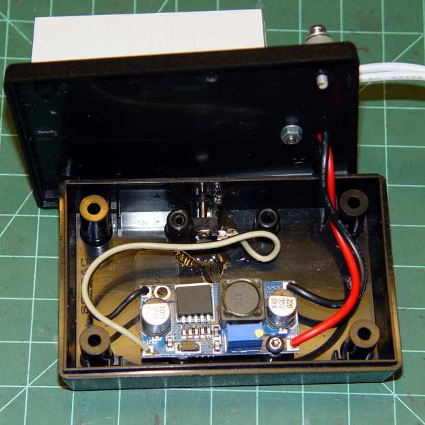
    The LEDs connected through a coaxial power jack on the far side of the box, held in place with a generous blob of epoxy:

    Needle LEDs power supply - interior
    Needle LEDs power supply – interior

    A closer look:

    Kenmore 158 COB LED - power supply jack
    Kenmore 158 COB LED – power supply jack

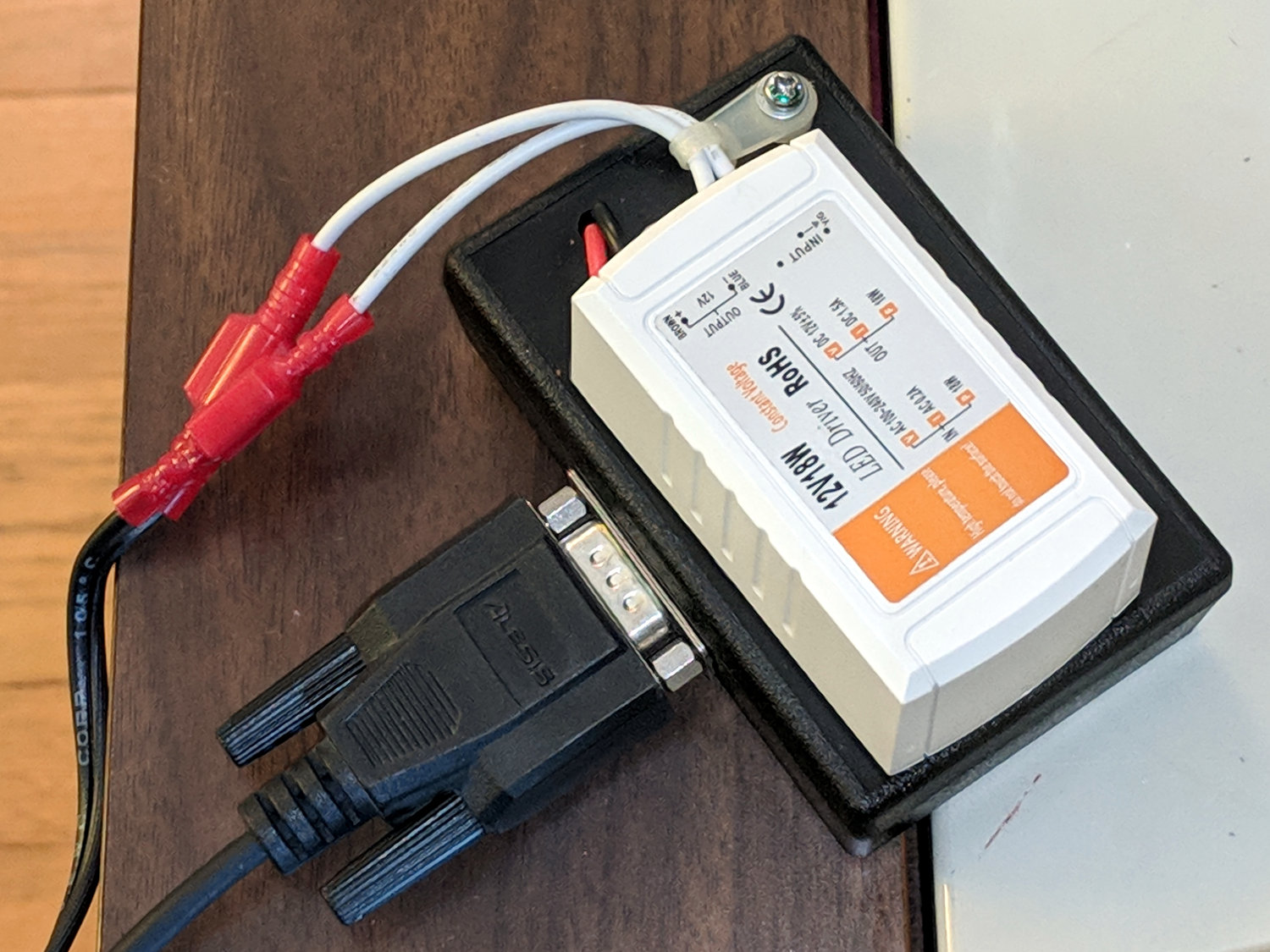
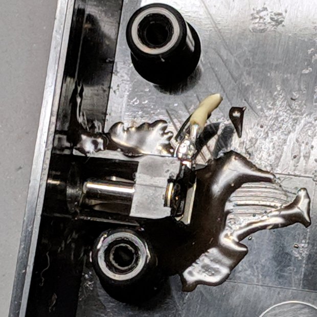
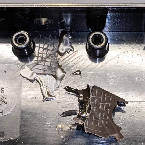
    I’m adding a light bar, similar to the one now going onto the Juki TL-2010Q, which needs a direct connection to the 12 VDC supply. Rather than add another coaxial jack, I ripped out the existing jack and installed a DE-9 connector (serial ports being a fading memory by now), giving me an opportunity to test the epoxy joint:

    Kenmore 158 COB LED - power supply jack - epoxy bond
    Kenmore 158 COB LED – power supply jack – epoxy bond

    Which required grabbing the connector with a pair of pliers and twisting / bending / abusing until it popped free. I don’t know how much grip the scored lines added to the joint, but the connector definitely didn’t give up without a fight; it wasn’t going to fall off on its own.

    To be fair, the epoxy had a better grip on the coaxial jack than on the plastic plate, perhaps because the bottom of the jack had all manner of nooks and pins intended for PCB mounting. Ya use what ya got, sez I.

    The new connector looks exactly like it should and, because it’s held in place by a pair of screws, should last forever, too:

    Kenmore 158 COB LED - power supply
    Kenmore 158 COB LED – power supply

    More about all that, later …

  • Juki TL-2010Q: COB LED Light Bar

    Mary needed more light under the arm of her Juki TL-2010Q sewing machine, so I proposed a 12 V 6 W COB LED module instead of the high-density LED strips I used on her Kenmore 158s:

    Kenmore 158 Sewing Machine - Cool white LEDs - rear no flash
    Kenmore 158 Sewing Machine – Cool white LEDs – rear no flash

    Because the COB LEDs dissipate 6W, far more power than I’m comfortable dumping into a 3D printed structure, I redefined a length of aluminum shelf bracket extrusion to be a heatsink and epoxied the module’s aluminum back plate thereto:

    Juki TL-2010Q COB LED - test lighting
    Juki TL-2010Q COB LED – test lighting

    Unlike the flexible LED strips, the COB LED modules have no internal ballast resistors and expect to run from a constant-current supply. Some preliminary testing showed we’d want less than the maximum possible light output, so a constant-voltage supply and a few ohms of ballast would suffice:

    Juki TL-2010Q COB LED - ballast resistor test
    Juki TL-2010Q COB LED – ballast resistor test

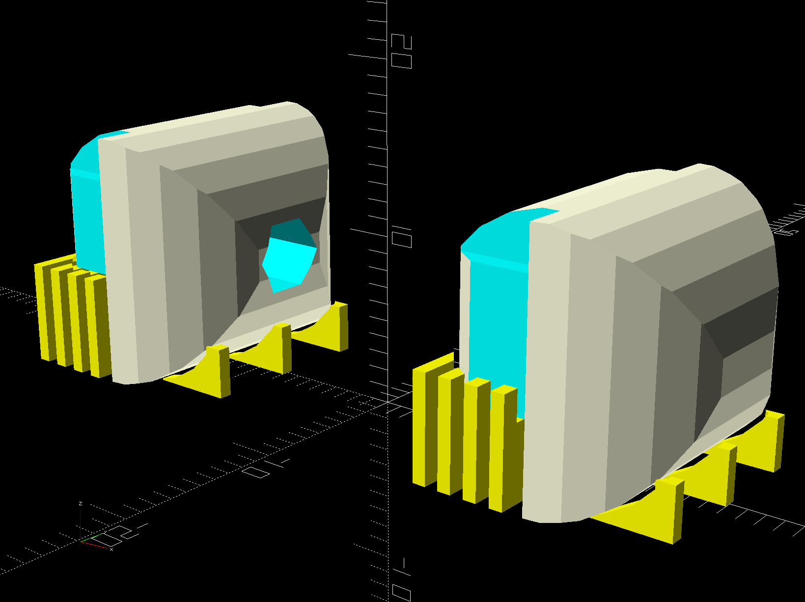
    With all that in hand, the heatsink extrusion cried out for smooth endcaps to control the wires and prevent snagging:

    TL-2010Q COB LED Light Bars - end caps - Show layout
    TL-2010Q COB LED Light Bars – end caps – Show layout

    The central hole in the left cap passes 24 AWG silicone wires from the power supply, with 28 AWG silicone wires snaking down through the L-shaped rectangular cutouts along the extrusion to the LED module’s solder pads.

    The model includes built-in support:

    TL-2010Q COB LED Light Bars - end caps - Build layout
    TL-2010Q COB LED Light Bars – end caps – Build layout

    Assuming the curved ends didn’t need support / anchors holding them down turned out to be completely incorrect:

    Juki TL-2010Q COB LED - curled endcaps
    Juki TL-2010Q COB LED – curled endcaps

    Fortunately, those delicate potato chips lived to tell the tale and, after a few design iterations, everything came out right:

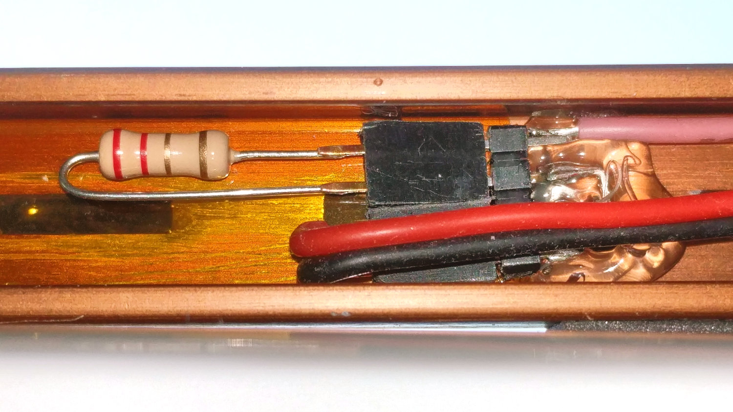
    Juki TL-2010Q COB LED - heatsink endcap - internal connections
    Juki TL-2010Q COB LED – heatsink endcap – internal connections

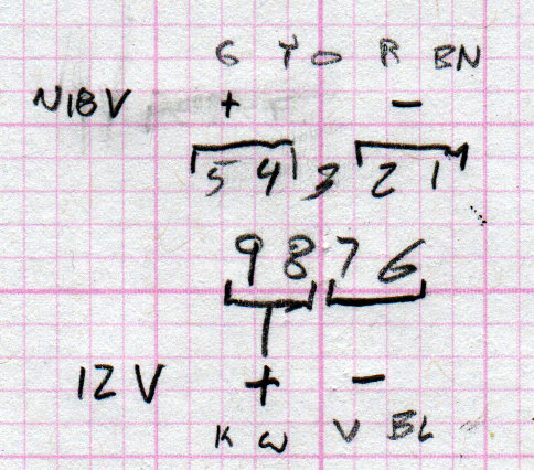
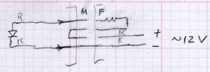
    The “connector”, such as it is, serves to make the light bar testable / removable and the ballast resistor tweakable, without going nuts over the details. The left side is an ordinary pin header strip held in place with hot melt glue atop the obligatory Kapton tape, because the heatsink doesn’t get hot enough to bother the glue. The right side is a pair of two-pin header sockets, also intended for PCB use. The incoming power connects to one set and the ballast resistor to the other, thusly:

    Juki TL-2010Q COB LED - light bar connector diagram
    Juki TL-2010Q COB LED – light bar connector diagram

    The diagram is flipped top-to-bottom from the picture, but you get the idea. Quick, easy, durable, and butt-ugly, I’d say.

    The next step was to mount it on the sewing machine and steal some power, but that’s a story for another day.

    The relevant dimensions for the aluminum extrusion:

    Aluminum shelf bracket extrusion - dimensions
    Aluminum shelf bracket extrusion – dimensions

    The OpenSCAD source code as a GitHub Gist:

    // Juki TL-2010Q Sewing Machine – COB LED Light Bars
    // Ed Nisley – KE4ZNU
    // 2019-01
    /* [Layout Options] */
    Layout = "Build"; // [Bracket,Endcap,Show,Build]
    Wiring = [1,0]; // left and right wire holes
    BuildSupport = true;
    /* [Extrusion Parameters] */
    ThreadWidth = 0.40;
    ThreadThick = 0.20;
    HoleWindage = 0.2;
    Protrusion = 0.1;
    //—–
    // Shelf bracket used as LED heatsink
    /* [Hidden] */
    LEDPlate = [15.0,2.4]; // 2D coords from end of LED
    BktOuter = [15.9,12.6 + LEDPlate.y]; // 2D coords as seen from end of extrusion
    BktWalls = [1.3,2.2 + LEDPlate.y]; // … extend base to cover LED
    BktCap = [2.5,3.0];
    BracketPoints = [
    [0,0],
    [BktOuter.x,0],
    [BktOuter.x,BktOuter.y],
    [(BktOuter.x – BktCap.x),BktOuter.y],
    [(BktOuter.x – BktCap.x),(BktOuter.y – BktCap.y)],
    [(BktOuter.x – BktWalls.x),(BktOuter.y – BktCap.y)],
    [(BktOuter.x – BktWalls.x),BktWalls.y],
    [BktWalls.x,BktWalls.y],
    [BktWalls.x,(BktOuter.y – BktCap.y)],
    [BktCap.x,(BktOuter.y – BktCap.y)],
    [BktCap.x,BktOuter.y],
    [0,BktOuter.y],
    [0,0]
    ];
    BracketPlugInsert = 10.0; // distance into bracket end
    WireOD = 1.6; // COB LED jumpers – 24 AWG silicone
    WireOC = BktOuter.x – 2*BktWalls.x – WireOD;
    echo(str("Wire OC: ",WireOC));
    CableOD = 4.0; // power entry cable
    CapSides = 2*3*4;
    //—–
    // Useful routines
    module PolyCyl(Dia,Height,ForceSides=0) { // based on nophead's polyholes
    Sides = (ForceSides != 0) ? ForceSides : (ceil(Dia) + 2);
    FixDia = Dia / cos(180/Sides);
    cylinder(r=(FixDia + HoleWindage)/2,
    h=Height,
    $fn=Sides);
    }
    //—–
    // Endcap with smooth rounding
    // Wires = true to punch holes for LED wires
    module Endcap(Wires = true) {
    // arc length to flatten inside of cap
    // not needed to build in normal orientation
    m = BktOuter.x/2 – sqrt(pow(BktOuter.x/2,2) – pow(BktOuter.x – 2*BktCap.x,2)/4);
    difference() {
    translate([0,0,BktOuter.y/2]) // basic endcap shape
    intersection() {
    cylinder(d=BktOuter.x,h=BktOuter.y,$fn=CapSides,center=true);
    rotate([90,0,0])
    rotate(180/CapSides)
    cylinder(d=BktOuter.y,h=BktOuter.x,$fn=CapSides,center=true);
    }
    translate([-BracketPlugInsert,0,0]) // extrusion + LED plate
    Bracket(BracketPlugInsert);
    if (false) // flatten inner end
    translate([-BktOuter.y + m,0,BktOuter.y/2])
    cube([BktOuter.y,BktOuter.x,BktOuter.y],center=true);
    if (Wires) {
    for (j=[-1,1]) // COB LED connections
    translate([WireOD – BktOuter.x/2,j*WireOC/2,(BktWalls.y + WireOD – Protrusion)/2])
    rotate([0,00,0])
    cube([BktOuter.x,WireOD + Protrusion,BktWalls.y + WireOD + Protrusion],center=true);
    translate([0,0,BktOuter.y/2]) // power entry / exit
    rotate([0,90,0])
    translate([0,0,-BktOuter.x])
    rotate(180/6)
    PolyCyl(CableOD,2*BktOuter.x,6);
    }
    }
    }
    // Totally ad-hoc support structures
    module Support(Wiring = false) {
    Spacing = 4*ThreadWidth;
    NumBars = floor((BktOuter.y/2) / Spacing);
    echo(str("Support bars: ",NumBars));
    color("Yellow") {
    render() difference() {
    union() {
    for (i=[1:NumBars]) // inside extrusion
    translate([-i*Spacing,0,(BktWalls.y + WireOD)/2])
    cube([2*ThreadWidth,BktOuter.x – 0*BktWalls.x,BktWalls.y + WireOD],center=true);
    if (true)
    for (j=[-1:1]) // reduce outside curve uplift
    translate([0.3*BktOuter.y,j*BktOuter.x/3,BktOuter.y/10])
    cube([BktOuter.y/3,2*ThreadWidth,BktOuter.y/5],center=true);
    }
    minkowski() { // all-around clearance
    Endcap(Wiring);
    cube(2.0*ThreadThick,center=true);
    }
    if (Wiring) {
    translate([0,0,BktOuter.y/2]) // remove rubble from wire bore
    rotate([0,90,0])
    translate([0,0,-BktOuter.x])
    rotate(180/6)
    PolyCyl(CableOD,2*BktOuter.x,6);
    }
    }
    if (false)
    translate([-(BktOuter.x/4 + ThreadWidth),0,ThreadThick/2]) // adhesion pad
    cube([BktOuter.x/2,BktOuter.x – BktWalls.x,ThreadThick],center=true);
    // translate([BktOuter.x/3,0,ThreadThick/2]) // adhesion pad
    // cube([0.3*BktOuter.x,0.7*BktOuter.x,ThreadThick],center=true);
    if (false)
    for (j = [-1:1]) // tie pad to bottom of cap
    translate([-(4*ThreadWidth)/2,j*(BktOuter.x – 2*ThreadWidth)/2,ThreadThick/2])
    cube([4*ThreadWidth,2*ThreadWidth,ThreadThick],center=true);
    }
    }
    //—–
    // Heatsink extrusion + LED plate
    // Centered on Y with Length extending in +X
    module Bracket(Length = 10)
    translate([0,-BktOuter.x/2,0])
    rotate([90,0,90])
    linear_extrude(height = Length,convexity=3)
    polygon(points=BracketPoints);
    //—–
    // Build things
    if (Layout == "Bracket")
    Bracket();
    if (Layout == "Endcap")
    Endcap();
    if (Layout == "Show") {
    translate([BktOuter.x,0,0])
    Endcap(Wiring[1]);
    translate([-BktOuter.x,0,0])
    rotate(180)
    Endcap(Wiring[0]);
    color("Yellow",0.35)
    translate([-BktOuter.x/2,0,0])
    Bracket(BktOuter.x);
    }
    if (Layout == "Build") {
    translate([BktOuter.y,0,0]) {
    Endcap(Wiring[0]);
    if (BuildSupport)
    Support(Wiring[0]);
    }
    translate([-BktOuter.y,0,0]) {
    Endcap(Wiring[1]);
    if (BuildSupport)
    Support(Wiring[1]);
    }
    }

  • Halogen Desk Lamp Conversion

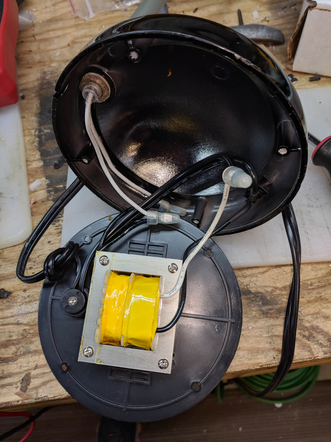
    As part of converting the halogen desk lamp to LEDs, I replaced the hulking iron transformer with a flatter counterweight:

    Halogen Desk Lamp - 12 V 20 W transformer
    Halogen Desk Lamp – 12 V 20 W transformer

    Under normal circumstances, you’d use something like steel or lead sheets, but Tiny Bandsaw™ can’t cut any appreciable thickness of steel and I gave away my entire lead stockpile, so I sawed disks from a pile of non-stick pancake griddles and drilled suitable mounting holes:

    Parallel clamps in action
    Parallel clamps in action

    Another disk (from a formal aluminum sheet!) goes into the lamp head, with a trio of 3W COB LEDs epoxied in place:

    Ex-Halogen Desk Lamp - 3x3W COB LED assembly
    Ex-Halogen Desk Lamp – 3x3W COB LED assembly

    The other side of the disk sports a heatsink harvested from a PC, also epoxied in place:

    Ex-halogen Desk Lamp - heatsink fitting
    Ex-halogen Desk Lamp – heatsink fitting

    Realizing the head required only a little filing to accommodate the heatsink sealed both their fates.

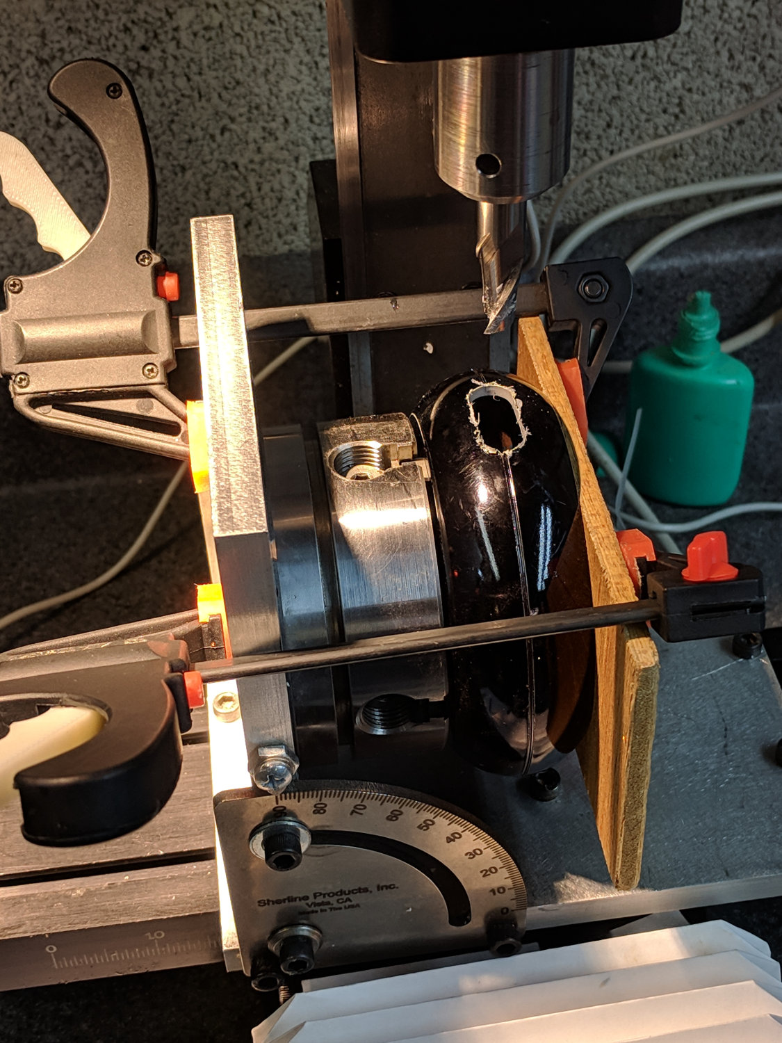
    A test firing showed the heatsink needed more airflow, which didn’t come as much of a surprise, so I milled slots in the lamp head:

    Ex-halogen Desk Lamp - vent slot milling
    Ex-halogen Desk Lamp – vent slot milling

    Deburring the holes, blackening the sides with a Sharpie, and tucking a bit of black window screen behind the opening made the vents look entirely professional.

    The small dome in the base originally cleared the transformer and now holds the entire 10 W LED driver, along with all the wiring, atop the counterweight sheets:

    Ex-halogen Desk Lamp - base wiring
    Ex-halogen Desk Lamp – base wiring

    A cork pad covers the base for a bit of non-skid action:

    Ex-halogen Desk Lamp - cork pad
    Ex-halogen Desk Lamp – cork pad

    I couldn’t convince myself filling in those sectors would improve anything, so I didn’t.

    And then It Just Worked:

    Ex-halogen Desk Lamp - in use
    Ex-halogen Desk Lamp – in use

    All without a trace of solid modeling or G-Code …

  • Kenmore Model 158 Pedal: Graphite Disk Refill

    The pedal on one of Mary’s Kenmore Model 158 sewing machines lost most of its speed control abilities, which past experience has shown indicates its carbon / graphite disks have deteriorated. Fortunately, I still have a supply of disks from the Crash Test Dummy machine and have gotten pretty good at dismantling the pedal housing.

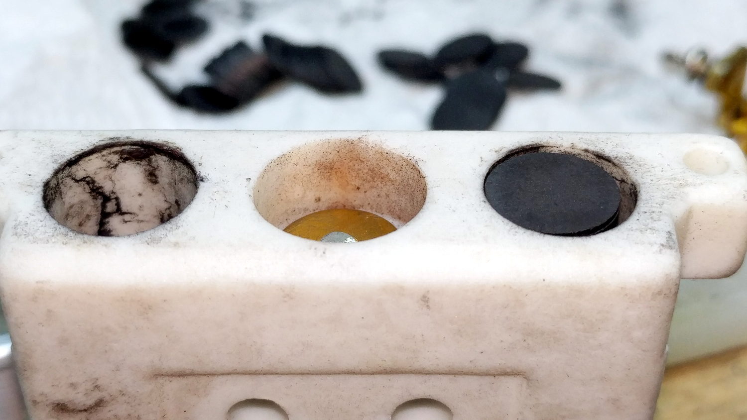
    While I had the pedal apart, I filed the brass contact plates smooth again:

    Kenmore 158 Pedal - graphite disk contact
    Kenmore 158 Pedal – graphite disk contact

    Most of the deterioration happens within half a dozen disks snuggled up against those contacts, a few more on the other end of the stack against the graphite button applying the pressure, and an occasional grimy disk in the middle of the stack.

    I filled both stacks flush to the top of the ceramic housing, then removed one disk from each to let the brass contacts slightly compress the stacks:

    Kenmore 158 Pedal - graphite disk refill
    Kenmore 158 Pedal – graphite disk refill

    A quick test showed the control range started a bit too fast, so I removed one more disk from the stacks, buttoned it up, and it’s all good again: a slow start with a good range.

  • Kenmore 158: First Needle LED Failure

    The first white LED fixture built to illuminate one of Mary’s Kenmore 158 sewing machines has been in regular use for the last four years:

    Kenmore 158 Sewing Machine - mixed LED lighting
    Kenmore 158 Sewing Machine – mixed LED lighting

    We never found a good time to rip-and-replace the “prototype” with brighter SMD LEDs and one of the LEDs finally gave up.

    They’re 10 mm white LEDs with five chips wired in parallel, which is obvious when you look into the remaining LED running at 1 mA:

    10 mm white LED - chips
    10 mm white LED – chips

    The center chip is just dimmer than the others, which means their QC doesn’t tightly control the forward voltage spec.

    The wire bonds on the anode terminal of the failed LED look a bit sketchy:

    10 mm white LED - wire bonds
    10 mm white LED – wire bonds

    Fortunately, I hadn’t removed the 120 VAC wiring for the original bulb and I have two OEM bulbs from other machines, so I just removed my LED gimcrackery, installed a good old incandescent bulb, and she’s back to sewing with a pleasantly warm machine.

    The fixture holding the LEDs broke apart as I extracted it, but it’ll never be used again:

    10 mm white LED - fixture
    10 mm white LED – fixture

    The LEDs are rated at 3.5 V and 200 mA (!), but were reasonably bright in series from a 6 V unregulated supply. Perhaps a power glitch killed the poor thing? We’ll never know.

    LEDs are reputed to have lifetimes in the multiple tens of thousands of hours, but I’ve seen plenty of failed automotive LEDs and fancy new LED streetlights out there, not to mention many dead and dying traffic signals. Seeing as how they’re in (presumably) well-engineered fixtures with good power supplies and are at most only a few years old, there shouldn’t be any failures yet.