The COB LED module claims to run at 12 V and 6 W, so it expects to draw 500 mA. First pass measurements showed 500 mA happened at 11.6 V:

The 12 VDC supply actually produced 12.1 V at 500 mA, so a 1 Ω 1/2 W resistor should produce the right current:
Which it did, but the Customer Base judged 6 W to be far too much light. A 2.7 Ω resistor seemed too dim, so we settled on 2.2 Ω:
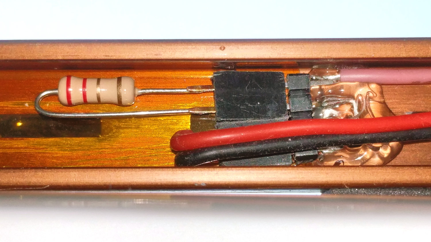
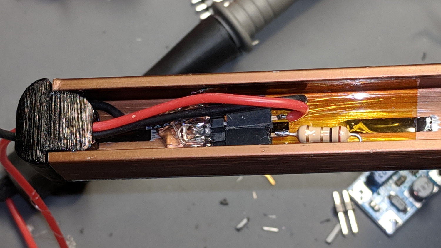
For the record, a 2.2 Ω resistor drops 980 mV and dissipates 440 mW, probably too close to its 500 mW rating. The supply produces 12.2 VDC at 450 mA, so the LEDs run at 11.2 V and dissipate 5 W; the heatsink remains pleasantly warm to the touch.
The hot melt glue anchoring the pin header won’t win any prizes, but it sticks like glue to the Kapton tape and, in any event, there’s not much to go wrong in there.
A cardboard cover hides the ugly details:
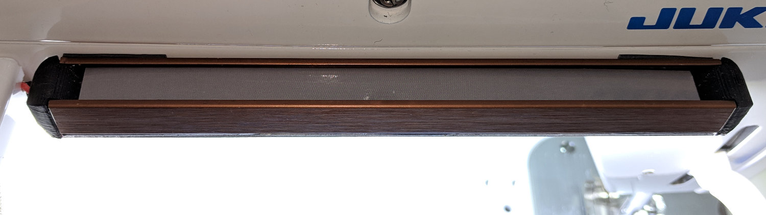
And then It Just Works™:

As evidenced by the glove fingertips, she does a lot of sewing and I’m glad I can shed some light on the subject …

Comments
13 responses to “Juki TL-2010Q: COB LED Light Levels”
Looking at your installation of the 2R2 resistor, I have occasionally added a blob (technical term!) of heat transfer paste between a resistor and the nearest heat sink to help thermal issues – not sure whether the thermal transfer helps or not but I do need to remember if I dismantle it to avoid extreme messiness!
Just a thought for discussion…
Simon
Suffice it to say: the Customer’s Requirements prohibit any substance that could possibly make its way onto the fabric under any circumstances. [grin]
Maybe replace the 2.2Ω resistor with two 1Ω in series to up the power dissipation abilities?
A sack of 1 W resistors just arrived from halfway around the planet and, when I pop the hood to install the new LED over the needle, I’ll Fix That Problem.
In truth, the resistor hasn’t gotten all brown & stinky, so I’m surely a worrywart.
Or replace the 2.2Ω resistor with four 2.2Ω resistors parallel and in series ;)
A sack of the cutest little 1/8 W resistors arrived a while ago, so just imagine what I could do with them!
My fridge broke down late one night so I chased down the problem to the CPU board, which had a burnt resistor and a cold solder joint on a relay pin. The joint was a quick fix, but I didn’t have a resistor of the appropriate value and wattage, so I built one out of eight smaller resistors. I ordered the correct (uprated) replacement, which I still have, but the array of smaller resistors has been in place for years and the fridge runs fine, so I’m just leaving them there until I have a reason to change them out.
I am running a 12V LED strip off a cheap little wal-wart preposterously labeled “12V 2000mA”. As I discovered, they meant to say “12V or 2A”, since under load voltage goes down to 11.something.
Which is nice: The brightness is now where I want it, and the LEDs might last longer. It’s not a bug, it’s a feature.
Perhaps “at most 12V, 2A, or smokeless” would be more reasonable? [sigh]
[…] complete control over the application, I’ll strip everything off the PCB and bond it to a heatsink of some sort. With 6 LEDs in […]
[…] more use and brightness tweaking, the COB light bars on the Juki TL-2010Q and Kenmore 158 now have 2.2 Ω ballast resistors setting the LED current to 370 mA and 300 mA, […]
[…] to wire the “5 W” COB LED to the 12 VDC supply grafted on the Juki TL-2010Q, through a suitable resistor around 18 Ω. Unfortunately, the next morning I managed to run 12 V directly to the LEDs, which […]
[…] combined illumination from the COB LED bar on the rear of the arm and the (renewed) COB LEDs over the needle does a pretty good job of lighting up the work […]