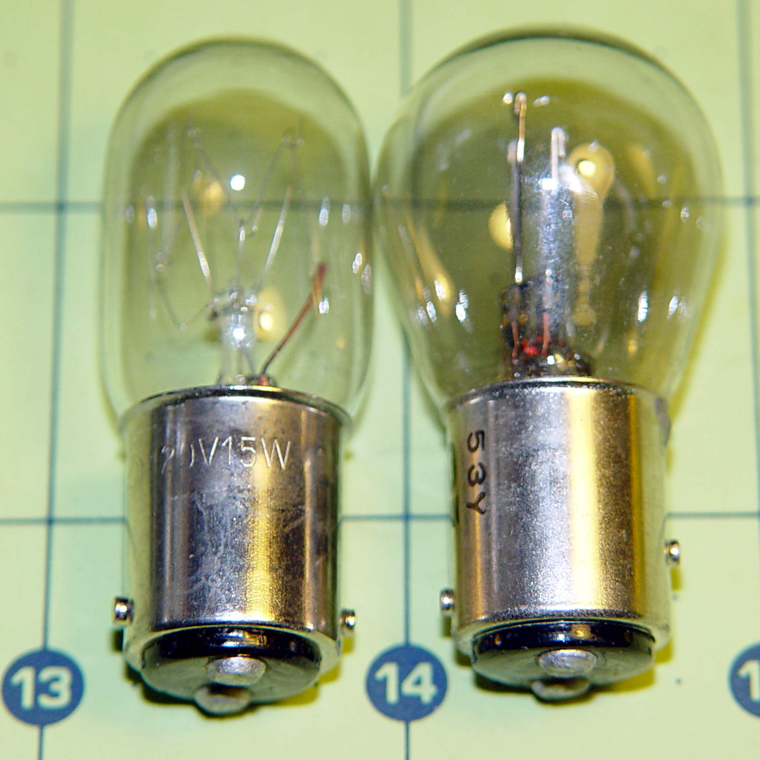
Mary wants more light directly around the needle of her Kenmore Model 158 sewing machine, as the existing light (a 120 V 15 W incandescent bulb tucked inside the end housing) casts more of a diffuse glow than a directed beam:
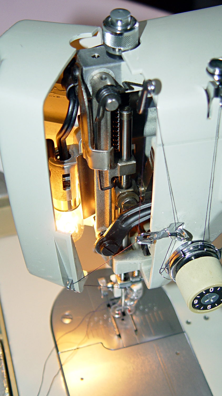
The end cap fits snugly around the bulb, but I thought a pair of 10 mm white LEDs, mounted side-by-side and aimed downward at the cover plate, would work. Of course, plugging a pair of white LEDs into a 120 VAC socket won’t work, but some judicious rewiring and a new 12 V DC wall wart will take care of that.
The bulb has a dual-contact bayonet base, with both pins isolated from the shell and connected to the non-polarized (!) line cord through the power switch. I didn’t know it was called a BA15d base, but now I do.
A 12 V automotive brake/taillight bulb (type 1157, I think) pulled from the Big Box o’ Bulbs has a slightly different pin arrangement that keys the filaments (which are not isolated from the shell) to the surrounding reflector:
So I conjured a mockup to see if it would fit, using 2-56 screws to mimic whatever hardware might be practical:

The solid model shows how it all fits together:

The two tiny ruby-red pins represent filament snippets in alignment holes, barely visible in real life:

I glued those pieces together, using a tiny machinist’s square as a jig to keep them perpendicular:

Some random 10 mm LEDs served for testing:

It actually fit pretty well, ignoring the fact that the LEDs point 90° from the intended direction (so I could see how the holes came out inside the pivot, honest), and lit up the area quite well, but it’s such a delicate affair that removing the entire socket and replacing it with a dedicated metal bracket / heatsink for two high-power SMD LEDs will be better.
The OpenSCAD source code:
// Adapter for LEDs in Sears sewing machine lamp socket
// Ed Nisley - KE4ZNU - January 2014

Layout = "Show";		// Build Show LEDTab LEDPlate ShellMount

//- Extrusion parameters must match reality!
//  Print with 2 shells and 3 solid layers

ThreadThick = 0.20;
ThreadWidth = 0.40;

HoleWindage = 0.2;			// extra clearance

Protrusion = 0.1;			// make holes end cleanly
Gap = 2.0;					// spacing between Show parts

AlignPinOD = 1.70;			// assembly alignment pins: filament dia

inch = 25.4;

//----------------------
// Dimensions

//-- LED mounting plate

LEDDia = 10.0;				// LED case OD
LEDFlangeOD = 10.7;

LEDPlateThick = 2.0;		// mounting plate thickness
LEDMargin = 2.0;

LEDSpaceOC = LEDDia + LEDMargin;		// LED center-to-center distance (single margin between!)

LEDTabLength = 15.0;		// base to screw hole center

LEDTabThick = 4.0;			// tab with hole for mounting screw
LEDTabScrewOD = 2.0;
LEDTabWidth = (3.0*2) + LEDTabScrewOD;

LEDMountHeight = 25.0;		// estimated mounting screw centerline to bottom of LEDs

//-- Lamp base adapter
//		hard inch dimensions!

ShellOD = 0.600 * inch;				// dia of metallic shell
ShellOAL = 0.66 * inch;				//  ... total length
ShellInsert = 7/16 * inch;			//  ... length engaging socket

ShellSides = 4*4;

BulbOD = 0.75 * inch;				// glass bulb
BulbLength = 1.14 * inch;

InsulOD = 0.485 * inch;				// insulating stub around contact pins
InsulThick = 0.070 * inch;			//  ... beyond end of shell

ContactOD = 2.0;					// contact holes through base (not heads)
ContactOC = 0.300 * inch;			//  ... center-to-center spacing

BayonetOD = 0.080 * inch;			// bayonet pin diameter
BayonetOffset = 0.125 * inch;		// from end of metal base

LampOAL = InsulThick + ShellOAL + BulbLength;
echo(str("Overall Length: ",LampOAL));

//-- Miscellany

//----------------------
// Useful routines

module PolyCyl(Dia,Height,ForceSides=0) {			// based on nophead's polyholes

  Sides = (ForceSides != 0) ? ForceSides : (ceil(Dia) + 2);

  FixDia = Dia / cos(180/Sides);

  cylinder(r=(FixDia + HoleWindage)/2,
           h=Height,
           $fn=Sides);
}

module ShowPegGrid(Space = 10.0,Size = 1.0) {

  Range = floor(50 / Space);

	for (x=[-Range:Range])
	  for (y=[-Range:Range])
		translate([x*Space,y*Space,Size/2])
		  %cube(Size,center=true);
}

//-- Tab for screw mounting LED holder
//		AddLength remains below Z=0 for good union

module LEDTab() {

	difference() {
		linear_extrude(height=LEDTabThick)
			hull() {
				circle(d=LEDTabWidth);
				translate([LEDTabLength/2,0,0])
					square([LEDTabLength,LEDTabWidth],center=true);
			}
		translate([0,0,-Protrusion])
			rotate(180/6)
				PolyCyl(LEDTabScrewOD,(LEDTabThick + 2*Protrusion),6);
		for (i=[-1,1])
			translate([LEDTabLength/2,i*LEDTabWidth/4,LEDTabThick/2])
				rotate([0,90,0]) rotate(180/4)
					PolyCyl(AlignPinOD,(LEDTabLength/2 + Protrusion),4);
	}
}

//-- Plate holding LEDs

module LEDPlate() {

	difference() {
		union() {
			linear_extrude(height=LEDPlateThick)
				hull() {
					for (i=[-1,1])
						translate([i*LEDSpaceOC/2,0,0])
							circle(d=(LEDDia + 2*LEDMargin));
					translate([0,(LEDFlangeOD/2 + LEDTabWidth/2),0])
						square([LEDTabThick,LEDTabWidth],center=true);
				}
		}
		for (i=[-1,1])
			translate([i*LEDSpaceOC/2,0,-Protrusion])
				rotate(180/12)
					PolyCyl(LEDDia,(LEDPlateThick + 2*Protrusion),12);
		for (i=[-1,1])
			translate([0,(i*LEDTabWidth/4 + LEDFlangeOD/2 + LEDTabWidth/2),3*ThreadThick]) rotate(180/4)
				PolyCyl(AlignPinOD,(LEDTabLength/2 + Protrusion),4);

	}
}

//-- Bulb shell mounting adapter

module ShellMount() {

	difference() {
		union() {
			cylinder(r1=InsulOD/2,r2=ShellOD/2,h=(InsulThick + Protrusion),$fn=ShellSides);
			translate([0,0,InsulThick])
				cylinder(r=ShellOD/2,h=(LampOAL - LEDMountHeight + LEDTabWidth/2),$fn=ShellSides);
		}

		translate([0,ShellOD,(InsulThick + BayonetOffset)])		// bayonet pin hole
			rotate([90,0,0]) rotate(180/4)
				PolyCyl(BayonetOD,2*ShellOD,4);

		translate([0,ShellOD,(InsulThick + LampOAL - LEDMountHeight)])		// LED mount screw hole
			rotate([90,0,0])
				PolyCyl(LEDTabScrewOD,2*BulbOD,6);

		translate([0,0,(InsulThick + ShellOAL + LampOAL/2)])		// slot for LEDTab mount
			cube([2*ShellOD,(LEDTabThick + 2*Protrusion),LampOAL],center=true);

		for (i=[-1,1])											// contact pin holes
			translate([i*ContactOC/2,0,-Protrusion])
				rotate(180/6)
					PolyCyl(ContactOD,2*LampOAL,6);
	}

}

//- Build it

ShowPegGrid();

if (Layout == "LEDTab")
	LEDTab();

if (Layout == "LEDPlate")
	LEDPlate();

if (Layout == "ShellMount")
	ShellMount();

if (Layout == "Show") {
	LEDPlate();
	translate([-LEDTabThick/2,(LEDFlangeOD/2 + LEDTabWidth/2),(LEDTabLength + LEDPlateThick + Gap)])
		rotate([0,90,0])
			LEDTab();
	for (i=[-1,1])
#	translate([0,(i*LEDTabWidth/4 + LEDFlangeOD/2 + LEDTabWidth/2),(LEDPlateThick + Gap/4)])
		rotate(180/4)
		cylinder(r=AlignPinOD/2,h=Gap/1,$fn=4);		// fake the pins

	translate([0,(LEDFlangeOD/2 + LEDTabWidth/2),(LampOAL - LEDTabWidth/2)])
		rotate([0,180,0]) rotate(90)
			ShellMount();
}

if (Layout == "Build") {
	translate([0,LEDDia,0])
		LEDPlate();

	translate([-10,-(LEDMargin + LEDTabWidth),0])
		rotate(-90)
			LEDTab();

	translate([10,-(LEDMargin + LEDTabWidth),0])
		ShellMount();
}
The original doodles for the bulb dimensions and adapter layout:


Comments
4 responses to “Sewing Machine Bulb: LED Replacement Doodle”
Actually the staggered bayonet pins in the automotive bulb aren’t for optical alignment, but so that the different filaments get connected to the proper circuits. If you manage to put it in backwards, you’ll get a bright parking light and a dim turn/brake light.
That bulb was a spare from the ’74 Turkey Valiant, so it’s been hiding for quite a while.
Whatever’s in the back end of the Sienna still lights up after 14 years…
[…] where the needle meets the fabric. I proposed LED strip lights on the machine arm, in addition to rebooting the end cap lamp into the current millennium, which […]
[…] trial fitting with the prototype showed that there’s no possible way to route the connections through the socket, no matter […]