The Smell of Molten Projects in the Morning

Ed Nisley's Blog: Shop notes, electronics, firmware, machinery, 3D printing, laser cuttery, and curiosities. Contents: 100% human thinking, 0% AI slop.

Tag: Sewing

Fabric arts and machines

  • Quilt Blocks: Scan and Montage

    Mary has been working on the Splendid Sampler project, with 56 completed blocks (*) stacked on her sewing table. We agreed that those blocks would make a nice background for our Christmas Letter, but the labor involved to photograph all the fabric squares and turn them into a page seemed daunting.

    Turned out it wasn’t all that hard, at least after we eliminated all the photography and hand-editing.

    The 6½x6½ inch blocks include a ¼ inch seam allowance on all sides and, Mary being fussy about such things, they’re all just about perfect. I taped a template around one block on the scanner glass:
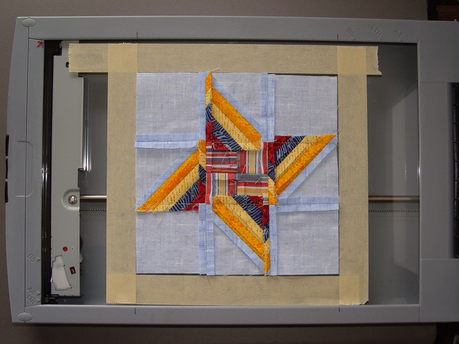
    Quilt block in scanner template
    Quilt block in scanner template

    Then set XSane to scan at 150 dpi and save sequentially numbered files, position a square scan area over the middle of the template, and turn off all the image enhancements to preserve a flat color balance.

    With “picture taking” reduced to laying each square face-down on the glass, closing the lid, and clicking Scan, the scanner’s throughput became the limiting factor. She scanned the blocks in the order of their release, while tinkering the auto-incremented file number across the (few) gaps in her collection, to produce 56 files with unimaginative auto-generated names along the lines of Block 19.jpg, thusly:
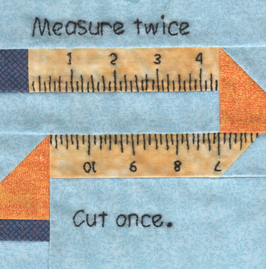
    Block 19
    Block 19

    The “square” images were 923×933 pixels, just slightly larger than the ideal finished size of 6 inch × 150 dpi = 900 pixel you’d expect, because we allowed a wee bit (call it 1/16 inch) on all sides to avoid cutting away the sharp points and, hey, I didn’t get the scan area exactly square.

    With the files in hand, turning them into a single page background image requires a single Imagemagick incantation:

    montage -verbose B*jpg -density 150 -geometry "171x173+0+0" -tile "7x" Page.jpg
    

    I figured the -geometry value to fill the 8 inch page width at 150 dpi, which is good enough for a subdued background image: 8 inch × 150 dpi / 7 images = 171 pixels. Imagemagick preserves the aspect ratio of the incoming images during the resize, so, because these images are slightly higher than they are wide, the height must be slightly larger to avoid thin white borders in the unused space. With all that figured, you get a 1197×1384 output image.

    Bumping the contrast makes the colors pop, even if they’re not quite photo-realistic:
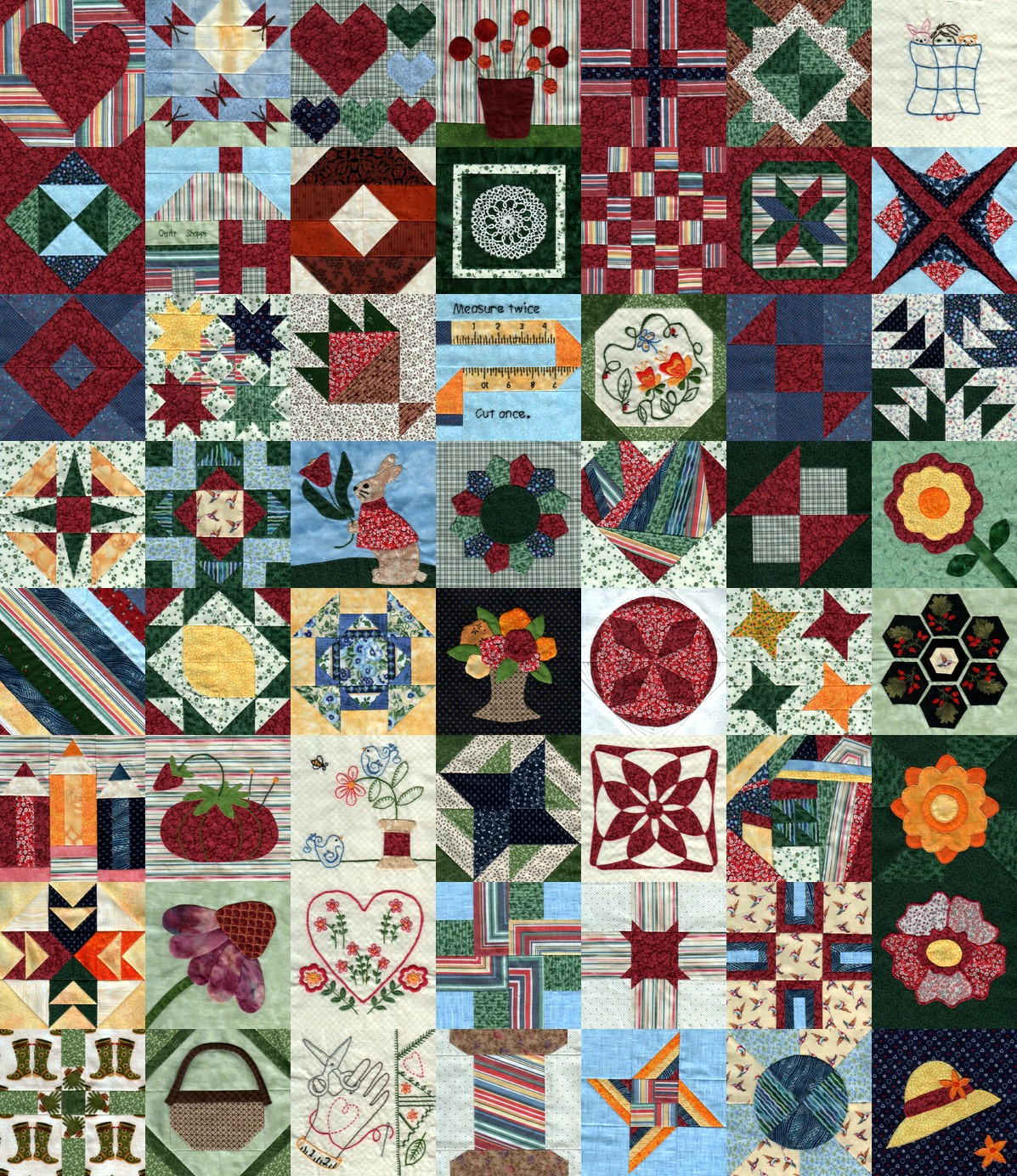
    Quilt block montage - contrast
    Quilt block montage – contrast

    I’ll lighten that image to make the Christmas Letter text (in the foreground, atop the “quilt”) readable, which is all in the nature of fine tuning.

    She has 40-odd blocks to go before she can piece them together and begin quilting, with a few other projects remaining to be finished:

    Mary quilting
    Mary quilting

    (*) She’s a bit behind the block schedule, having had a year of gardening, bicycling, and other quilting projects, plus whatever else happens around here. Not a problem, as we see it.

  • Wearable Electronics: Connections

    Although I’m not the type of guy who thinks twinkly LEDs will enhance his apparel, one of Mary’s quilting thread sources had a closeout deal on their “wearable electronics”, including a large cone of stainless steel thread / yarn:

    Stainless steel thread
    Stainless steel thread

    … CR2032 lithium cells & holders, plus assorted LEDs on small PCBs.

    The usual advice for connecting the thread seems to involve knotting it through the PCB holes, then sewing it to the backing fabric. Alas, I’m bad with knots and the stainless steel yarn isn’t all that cohesive:

    Emerald LED - Stainless steel thread - knotted
    Emerald LED – Stainless steel thread – knotted

    The holder has an even smaller hole, but Mary gave me a needle threader that helped:

    CR2032 - Stainless steel thread - knotted
    CR2032 – Stainless steel thread – knotted

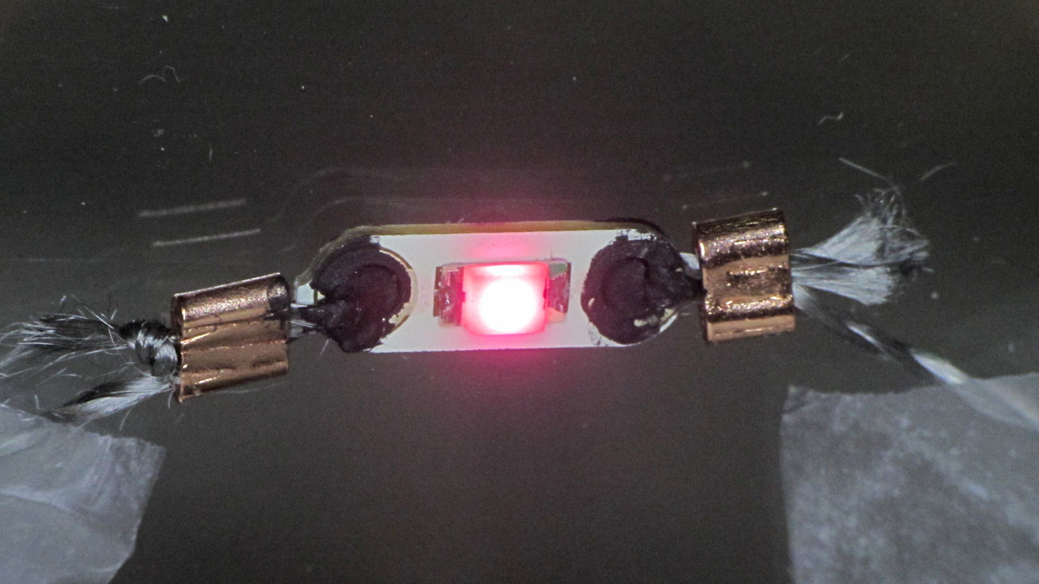
    Some advice found on The InterTubes suggests using copper crimp beads (perhaps with solder) to prevent the thread from completely unraveling and keep the thread loop tight around the PCB hole:

    Rose LED - Stainless steel thread - Crimp bead - Wire Glue
    Rose LED – Stainless steel thread – Crimp bead – Wire Glue

    Beadworkers use crimping pliers that leave a tidy dent; I mashed the beads with a needlenose pliers and called it good.

    The LEDs seem to be white LEDs with filters or, perhaps, blue / violet LEDs with different phosphors: their forward voltages look more blue than red or green. Everybody in this field depends on the minor miracle that lithium cell voltages match blue LED forward drops closely enough that you can get away without a ballast resistor.; the cell’s 20-ish Ω internal resistance doesn’t hurt in the least. An interesting white paper (SWRA349) from TI explores the effect of current on cell capacity and how to size a parallel capacitor that reduces the peak battery current.

    The black gunk is Wire Glue, which costs about five bucks for a lifetime supply in a small jar (or nigh onto 15 bucks via Amazon Prime) and is basically carbon powder in a water-based binder. Apply a dab to the connection and the water evaporates to leave the carbon + binder behind.

    That works better on joints that don’t move, which is precisely what you don’t have in a wearable electronic situation. You can see the crumbling Wire Glue after the trip back from a Squidwrench meeting:

    CR2032 - Stainless steel thread - Crimp bead - Wire Glue
    CR2032 – Stainless steel thread – Crimp bead – Wire Glue

    I also picked up a Permatext Rear Window Defogger repair kit (09117, if you’re looking) that seems to be a staggeringly expensive way to get a tenacious high-current conductive adhesive. More on that later.

    The yarn runs 3.5 Ω/ft, much lower than Adafruit’s three-ply yarn (10 Ω /ft), and suggests itself for flexible connections, EMI gaskets, and suchlike.

    Those LEDs are taped to the kitchen window, where they cast a cool light over the table, with the battery holders sitting on the sash. I’d just replaced some data logger CR2032 cells, so they’re running from nearly dead lithium batteries.

    For future reference: 2.77 V and falling, pushing less than 2 mA through the LEDs.

  • Pencil Guides for Ruler Quilting

    Mary has been doing Ruler Quilting and wanted a pencil guide (similar to the machine’s ruler foot) to let her sketch layouts before committing stitches to fabric. The general idea is to offset the pencil by 1/4 inch from the edge of the ruler:

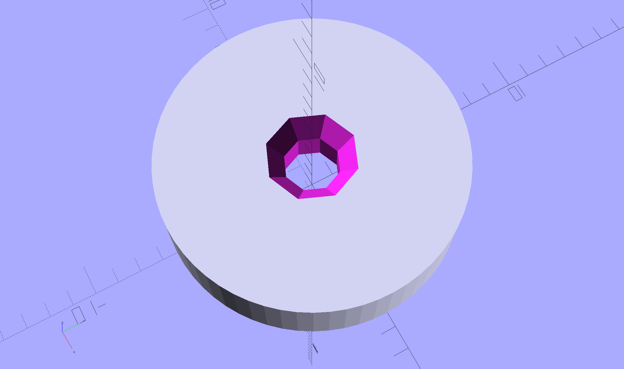
    Ruler Adapter - solid model
    Ruler Adapter – solid model

    That was easy.

    Print three to provide a bit of cooling time and let her pass ’em around at her next quilting bee:

    Ruler Adapter - Slic3r preview
    Ruler Adapter – Slic3r preview

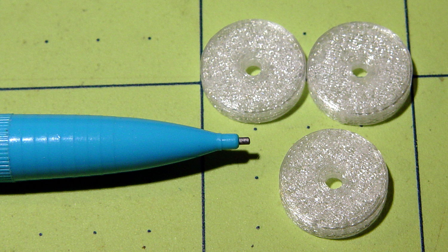
    Her favorite doodling pencil shoves a 0.9 mm lead through a 2 mm ferrule, so ream the center hole with a #44 drill (86 mil = 2.1 mm) to suit:

    Ruler quilting pencil guides
    Ruler quilting pencil guides

    The outer perimeters have 64 facets, an unusually high number for my models, so they’re nice & smooth on the ruler. Even though I didn’t build them sequentially, they had zero perimeter zits and the OD came out 0.500 inch on the dot.

    The chamfers guide the pencil point into the hole and provide a bit of relief for the pencil’s snout.

    If I had a laser cutter, I could make special rulers for her, too …

    The OpenSCAD source code as a GitHub Gist:

    // Quilting Ruler Adapters
    // Ed Nisley KE4ZNU October 2016
    //- Extrusion parameters must match reality!
    ThreadThick = 0.25;
    ThreadWidth = 0.40;
    HoleWindage = 0.2;
    Protrusion = 0.1; // make holes end cleanly
    inch = 25.4;
    function IntegerMultiple(Size,Unit) = Unit * ceil(Size / Unit);
    //———-
    // Dimensions
    ID = 0;
    OD = 1;
    LENGTH = 2;
    Offset = 0.25 * inch;
    Template = [2.0,2*Offset,3.0];
    NumSides = 16*4;
    HoleSides = 8;
    //———————-
    // Useful routines
    module PolyCyl(Dia,Height,ForceSides=0) { // based on nophead's polyholes
    Sides = (ForceSides != 0) ? ForceSides : (ceil(Dia) + 2);
    FixDia = Dia / cos(180/Sides);
    cylinder(d=(FixDia + HoleWindage),h=Height,$fn=Sides);
    }
    //———-
    // Build it
    difference() {
    cylinder(d=Template[OD],h=Template[LENGTH],$fn=NumSides);
    translate([0,0,-Template[LENGTH]])
    PolyCyl(Template[ID],3*Template[LENGTH],HoleSides);
    translate([0,0,-Protrusion])
    cylinder(d1=2*Template[ID],d2=Template[ID],h=Template[LENGTH]/3 + Protrusion,$fn=HoleSides);
    translate([0,0,Template[LENGTH] + Protrusion])
    mirror([0,0,1])
    cylinder(d1=2*Template[ID],d2=Template[ID],h=Template[LENGTH]/3 + Protrusion,$fn=HoleSides);
    }
  • Kenmore Model 158: Needle Lights, Now With Moah LEDs

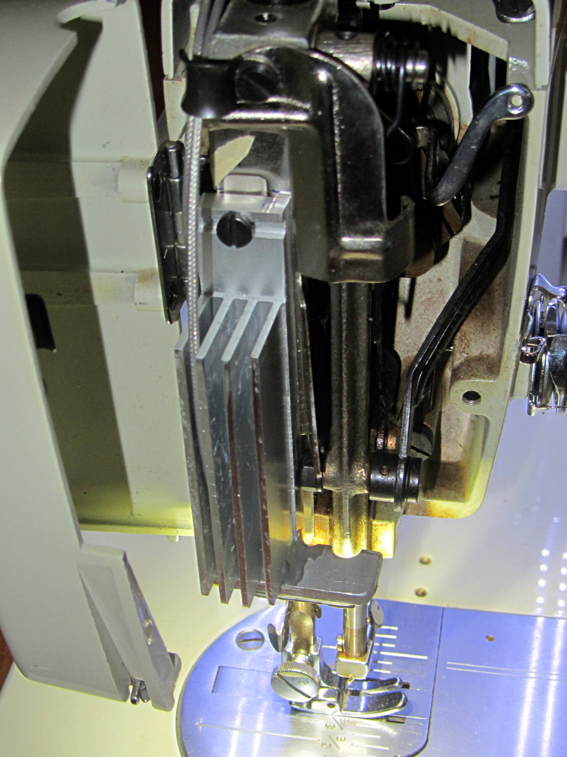
    The first pass at retrofitting SMD LEDs to light the needle area in Mary’s Model 158 sewing machine worked well enough:

    Kenmore 158 Needle Light - heatsink
    Kenmore 158 Needle Light – heatsink

    However, she wanted more light on the right side of the needle, so now she has it:

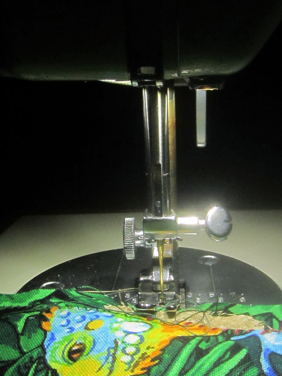
    Needle LEDs - front
    Needle LEDs – front

    That’s without any LEDs along the front and back of the arm, hence the dark pool beyond the sewing machine’s base.

    Those are the same 5050 warm white LEDs I used on the other side:

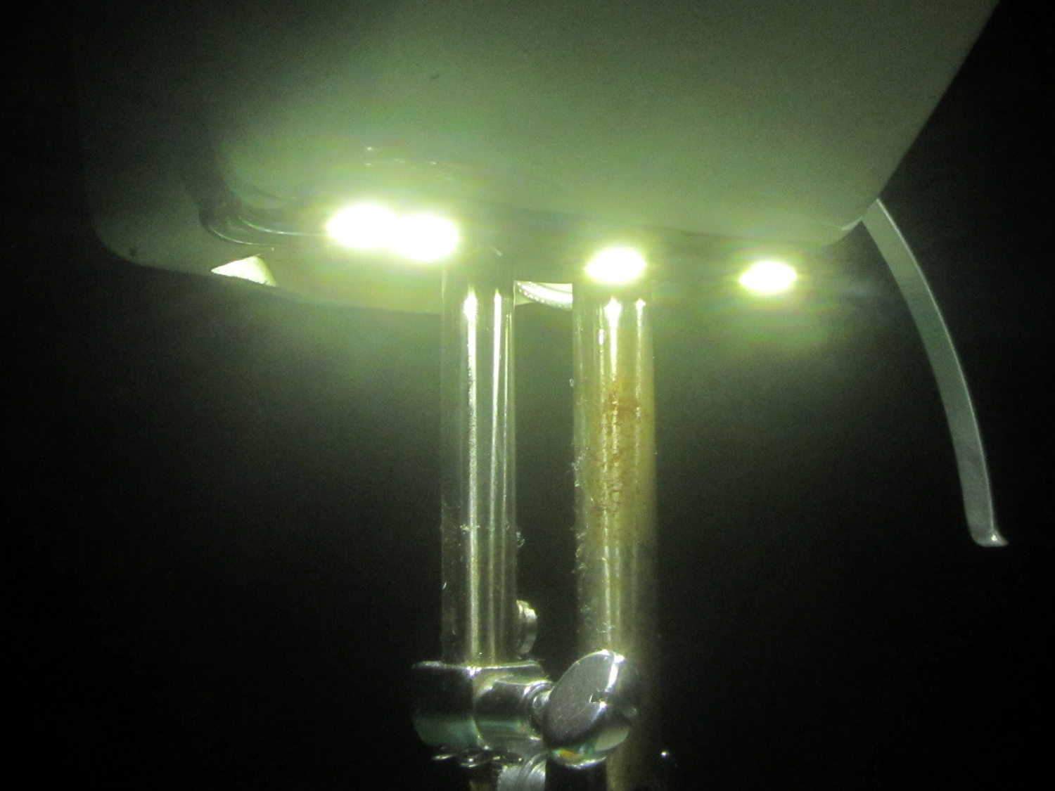
    Needle LEDs - lower right
    Needle LEDs – lower right

    Seen without the glare:

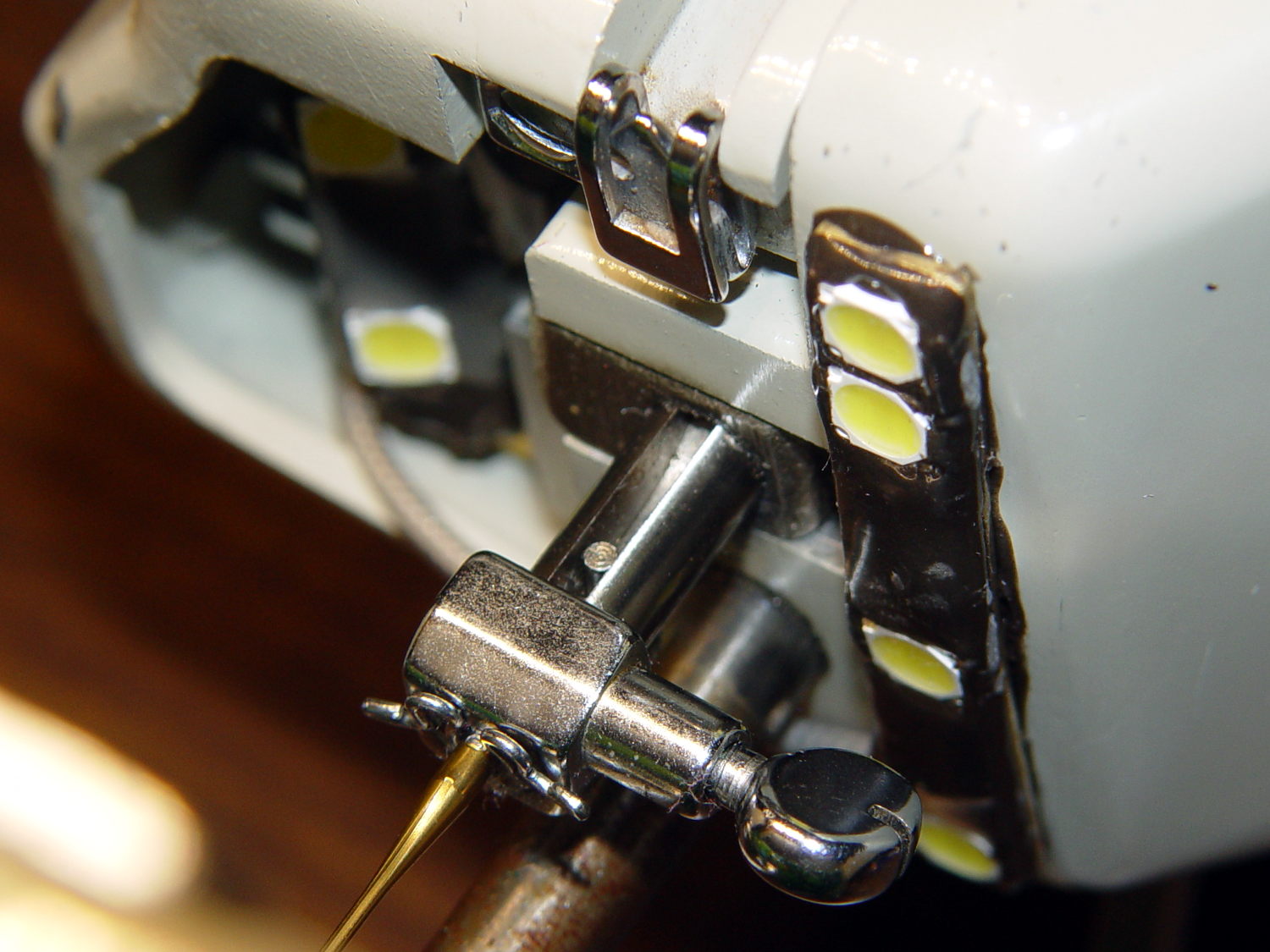
    Needle LEDs - bottom
    Needle LEDs – bottom

    They’re mounted on a 32 mil brass strip from the shimstock stash, carefully hand-bent and twisted to match the curvature of the arm, and held in place with JB Kwik steel-filled epoxy for good heat conduction to the aluminum arm. One can argue with the epoxy oozing out from under the brass, but it’s invisible from above.

    No construction photos, alas, because I made this in a white-hot frenzy one afternoon and managed to not take any pix during the entire session. Call it working in the flow, OK?

    All four SMD LEDs sit in epoxy blobs that isolate them from the brass strip, with 26 AWG solid wire “bus bars” soldered to the top of their terminals and a length of that lovely PTFE-insulated miniature coax leading off into the endcap. More epoxy encloses all the wiring & connections to provide a surprisingly smooth surface that shouldn’t snag the fabric.

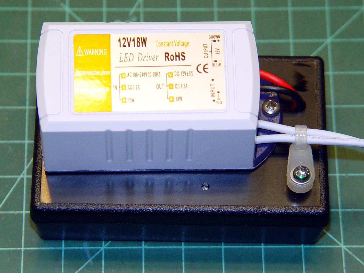
    The power supply uses an 18 W 120 VAC to 12 VDC brick intended for small LED installations:

    Needle LEDs power supply - exterior
    Needle LEDs power supply – exterior

    The AC comes from the same zip cord that formerly supplied the original 15 W incandescent bulb in the endcap, so the new lights behave the same way: push the power button to turn on the machine and the LEDs pop on just like they should. I put quick-disconnect terminals in the AC line to make it removable, although those need some sort of insulated plug to cover the exposed blades inside their housing.

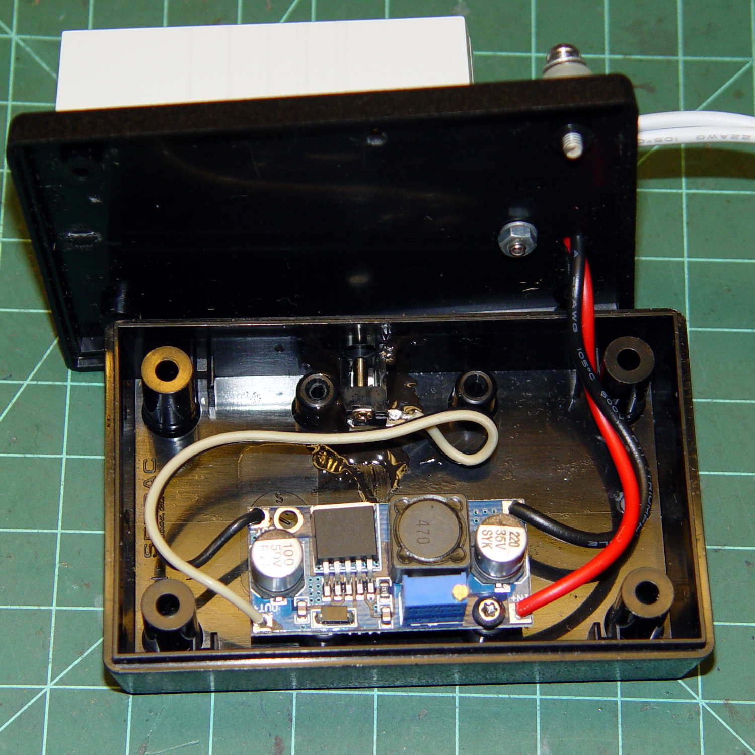
    Inside the black box, a small boost supply steps the voltage up to just under the nominal operating level of 21 VDC:

    Needle LEDs power supply - interior
    Needle LEDs power supply – interior

    You can just see the adjusting screw hole in front of the AC brick in the overall view.

    The DC output exits in the middle of the far side, through a coax jack epoxied to the base.

    As before, all six LEDs run in parallel at (for now) 18.5 VDC and maybe 50 mA each, for a total of 300 mA, and seem fearsomely bright even at that. We can now tune for best light as needed.

    This is a major major major improvement over the previous tangle of wires stuck on the outside of the machine, with all the wiring internal to the arm and the power supply out of sight under the sewing table.

    After an hour, the arm above the four LEDs runs 13 °C above ambient and the endcap over the two LED heatsink is 6 °C over ambient. The AC supply runs at 104 °C and its plastic case offers no provision for heatsinking. All in all, things are warm and not hazardous.

    I haven’t retrofit this machine with LED strips along the front & back of the arm, as those may not be needed with the intense needle lighting; the NisLite desk lamp may suffice for area illumination.

  • Kenmore Model 158 Power Switch: Laying-on-of-hands Repair

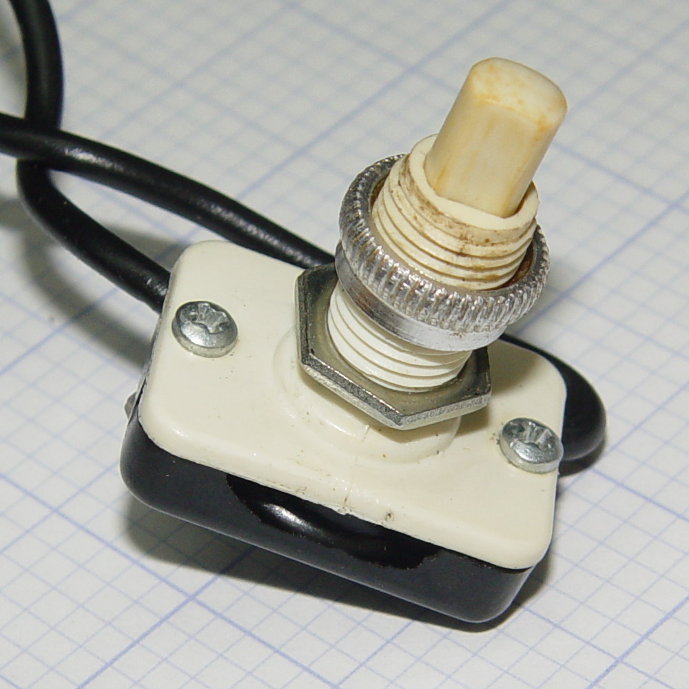
    The power switch on Mary’s “embroidery” Kenmore Model 158 sewing machine became exceedingly stiff, to the extent she said it was painful to push. Buying a shiny new switch seemed iffy, because a cursory search through the usual reputable electronic suppliers suggested there’s no way to specify how stiff the button might be, nor how that might feel in actual practice.

    The switch harvested from the pulse-drive machine felt somewhat less stiff, so I decided to (try to) loosen it up and, if that worked, swap it for the stubborn one.

    A pair of rivets hold the two halves of the switch together, obviously intended as a permanent solution. A carbide burr in the Dremel tool dealt with them easily enough:

    Model 158 Power Switch - grinding rivets
    Model 158 Power Switch – grinding rivets

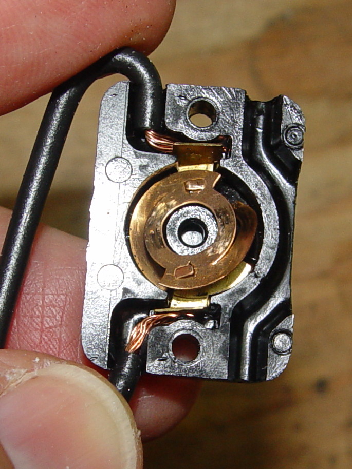
    Inside, the actuator drives a rotating brass contact:

    Model 158 Power Switch - rotor
    Model 158 Power Switch – rotor

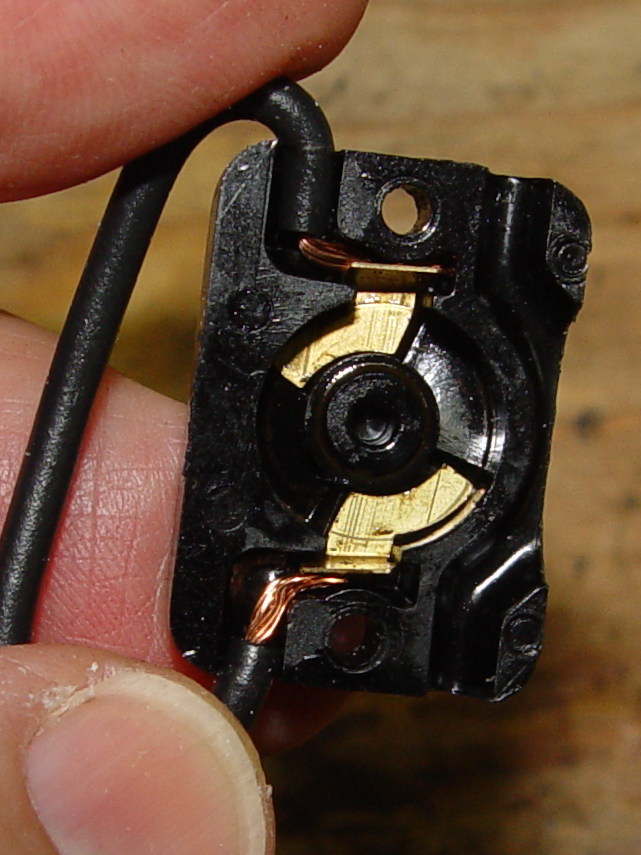
    Two stationary brass contacts are spot-welded to the wires:

    Model 158 Power Switch - contacts
    Model 158 Power Switch – contacts

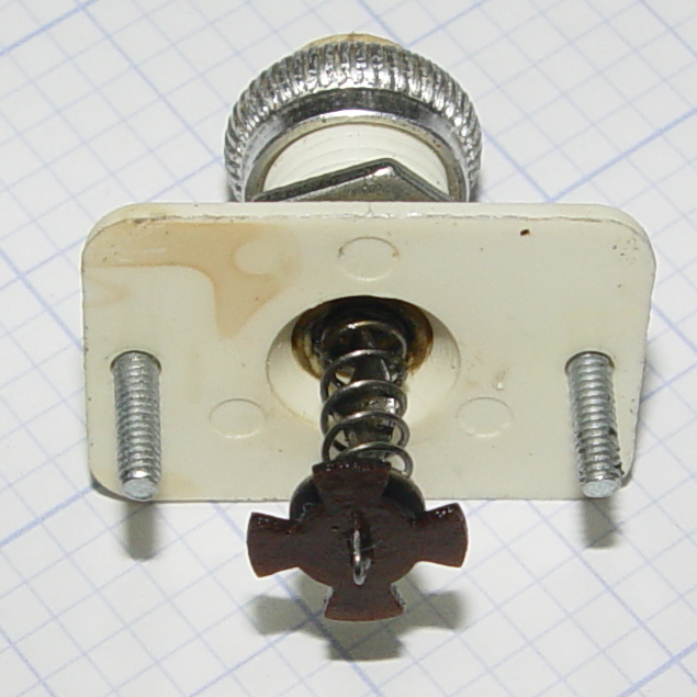
    The actuator under the button consists of a helix-twisted steel rod, a rather stiff spring, and a four-vaned phenolic blade that engages those two little flaps on the rotor. The rivet holes exactly fit plain old 1-72 screws:

    Model 158 Power Switch - actuator stem
    Model 158 Power Switch – actuator stem

    Not seeing anything obviously fix-able inside, I wiped the excess oil off and reassembled it in reverse order:

    Model 158 Power Switch - reassembled
    Model 158 Power Switch – reassembled

    Astonishingly, that bit of attention loosened it up: the button now presses easily!

    I swapped it with the too-stiff switch and declared victory…

  • Kenmore 158.17032: Mystery Spring

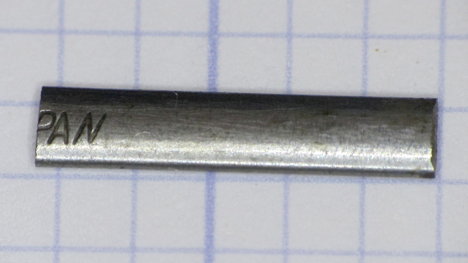
    This steel strip emerged from inside the arm of the Kenmore 158.17032 sewing machine that we’ve been reconditioning for one of Mary’s friends:

    Kenmore 158.17032 - mystery spring
    Kenmore 158.17032 – mystery spring

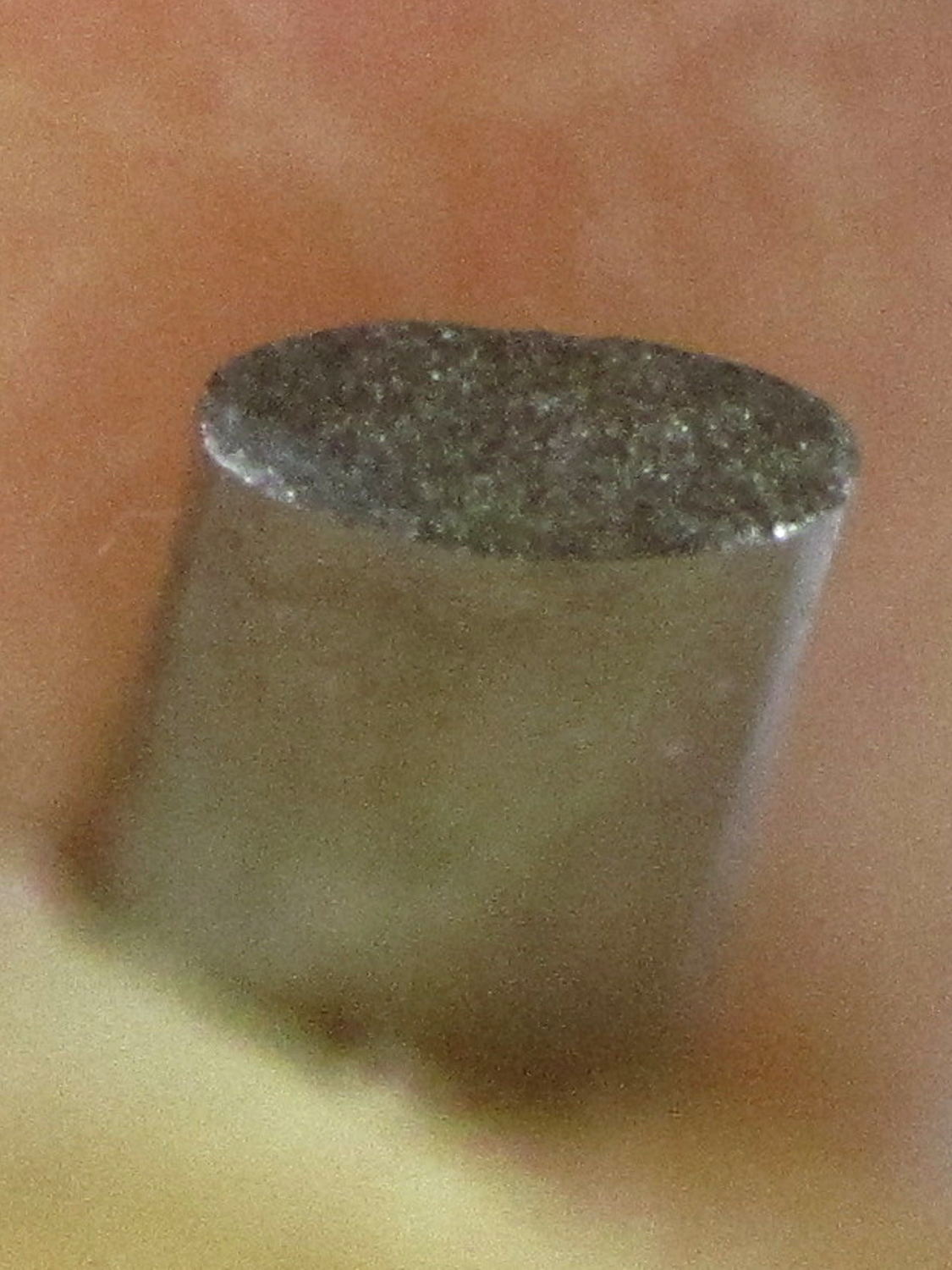
    The ends show the granular fracture of hard steel:

    Kenmore 158.17032 - mystery spring - end view
    Kenmore 158.17032 – mystery spring – end view

    It’s 13.3 mm long, 1.0 mm thick, tapers slightly from 2.8 mm on the end that once said “Japan” to 2.76 mm on the other, and that’s all we know about it.

    The sewing machine seems to work well enough without it (after some clean-and-lube action) and we haven’t found where the piece came from, but circumstantial evidence suggests it’s part of a spring somewhere inside the arm. It’s in a little bag with all the other random sewing machine parts I’ve collected along the way; perhaps some day we’ll know more and I can fabricate a replacement.

  • Kenmore 158.17032 Handwheel Clutch Disassembly

    One of Mary’s friends asked us to take a look at her Kenmore 158.17032 sewing machine that suffered from a Showstopper Problem: the handwheel turned the main shaft, but the motor pulley spun freely. You could rev the motor to maximum speed without budging the shaft, which suggested something was wrong with the clutch joining the handwheel and the belt pulley to the main shaft. This being a slightly newer model than the others in our stable, I was mildly surprised to find a completely different clutch mechanism between the drive belt and the main shaft.

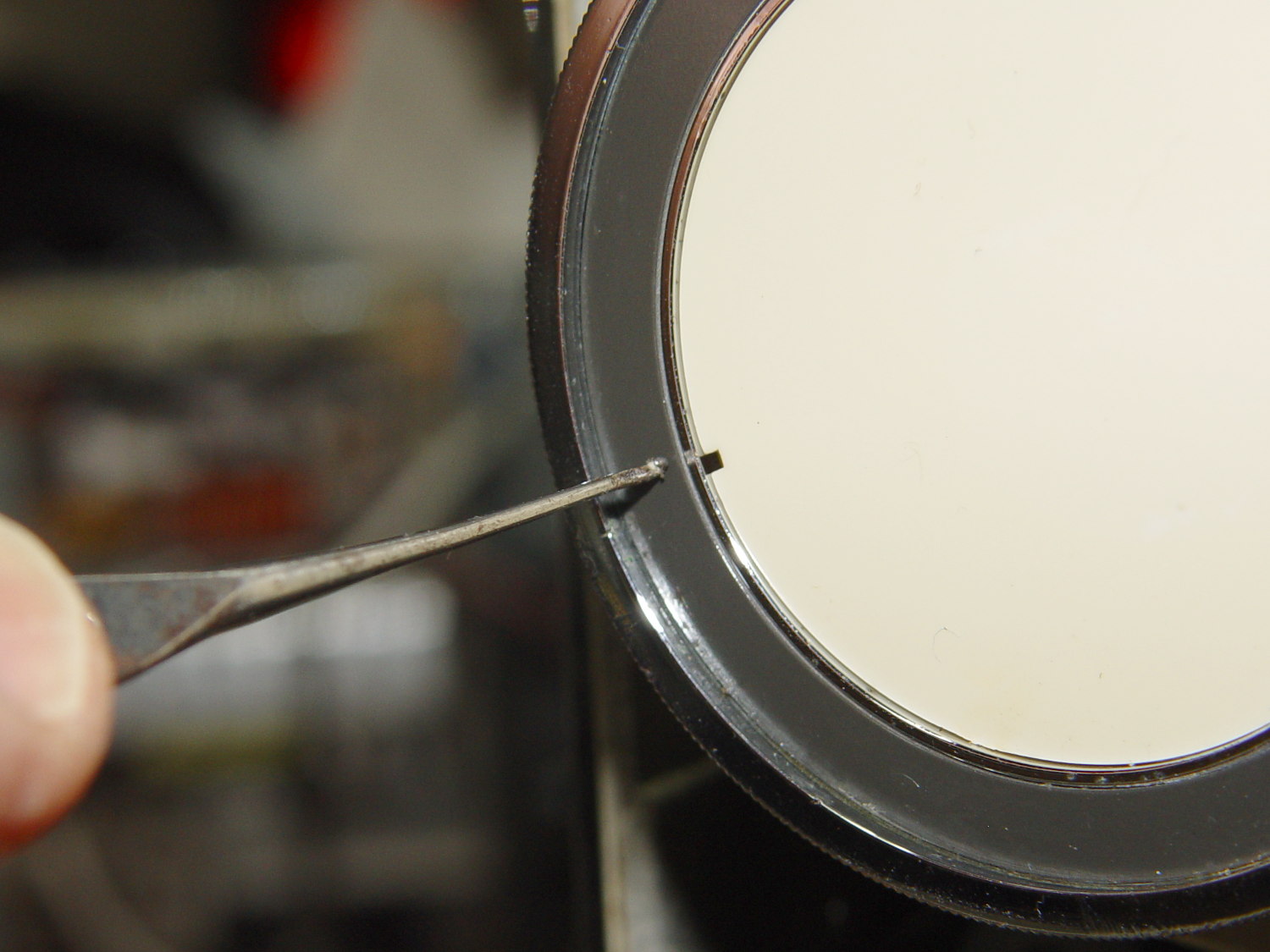
    The plastic cover plate in the handwheel yielded to an old crochet hook:

    Kenmore 158.17032 - Handwheel cap removal
    Kenmore 158.17032 – Handwheel cap removal

    Stick the hook into the tiny notch, engage hook with cover, pull outward, and it’ll fall into your other hand.

    That exposes a simple screw holding the chromed plastic handwheel in place on the motor shaft. After taking the pulley and clutch off the Hard Way, I discovered the Right Way, which is hereby documented for The Next Time Around. In order to show what’s needed, I’ll start in the middle and work outward.

    Pull the handwheel off and remove the machine’s end cover.

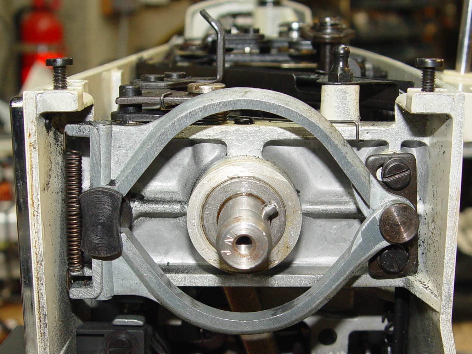
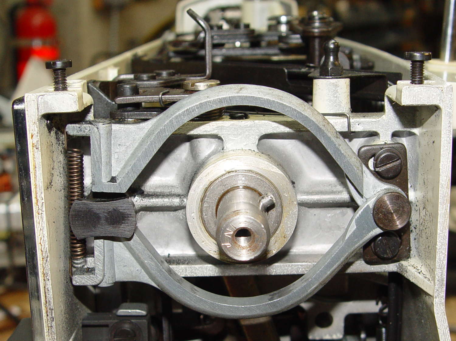
    With the clutch assembly removed (which you can’t do yet), you can see a pair of pot metal bands that act as a brake when the bobbin winder snaps off a full bobbin. They look like this in the normal running position:

    Kenmore 158.17032 - Clutch trip lever - normal position
    Kenmore 158.17032 – Clutch trip lever – normal position

    The black bow-tie at 9 o’clock is vertical, holding the brake bands apart and clearing the tab on the clutch asembly (which you haven’t seen yet).

    They look like this when the bobbin winder has just snapped:

    Kenmore 158.17032 - Clutch trip lever - bobbin wind position
    Kenmore 158.17032 – Clutch trip lever – bobbin wind position

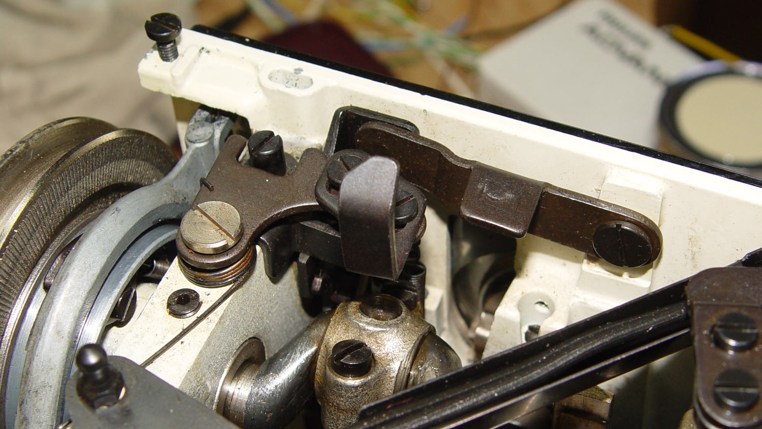
    The Bobbin Winder Reset Button atop the machine (which our machines don’t have and this one does) presses on the tab sticking out toward you on the horizontal bar pivoting on the front of the machine:

    Kenmore 158.17032 - Bobbin winder reset lever
    Kenmore 158.17032 – Bobbin winder reset lever

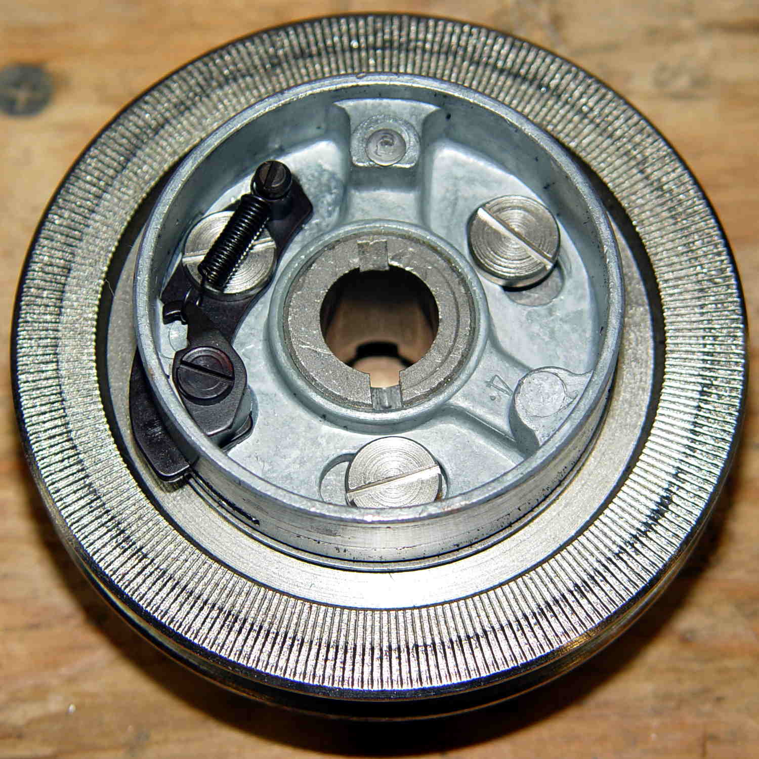
    In that position, the button is up, the bobbin is ready to load, the brake bands are off, and you can gently tap the clutch assembly off the main crankshaft:

    Kenmore 158.17032 - Handwheel clutch assembly
    Kenmore 158.17032 – Handwheel clutch assembly

    The inner hub rotates very slightly with respect to the belt drive pulley (which has the grooves that drive the bobbin winder tire). That didn’t quite work on this machine, due to the usual lack of lubrication / mechanical wear / what-have-you.

    The innermost part (with the notches for the pin visible at 2 o’clock on the main shaft) rotates with the handwheel. The belt pulley rotates with the motor belt. The clutch lets you turn the handwheel with the motor stopped. Normal rotation is clockwise in this view; on the machine, you turn the top of the wheel toward you.

    Carefully remove the spring that retracts the clutch lever, remove both black screws, remove the big flat head screw, and slide the black lever out to the side.

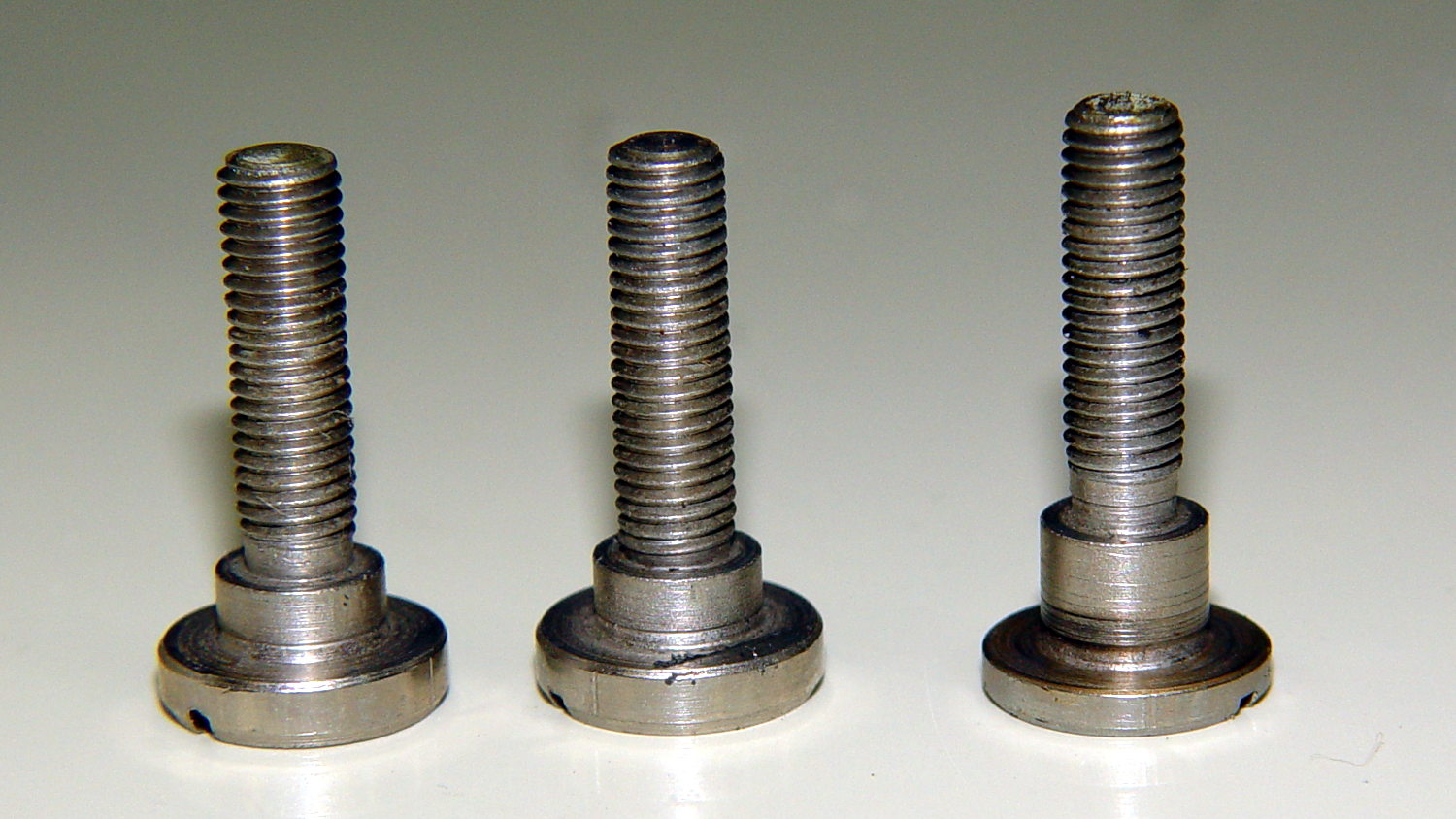
    Unscrew the two remaining flat-head screws holding the hub / lever in place. The one with the longer shoulder goes into the lever:

    Kenmore 158.17032 - Handwheel clutch screws
    Kenmore 158.17032 – Handwheel clutch screws

    Removing the hub reveals the pin that engages the clutch mechanism visible through the slot at 6 o’clock in the handwheel:

    Kenmore 158.17032 - Handwheel clutch dog
    Kenmore 158.17032 – Handwheel clutch dog

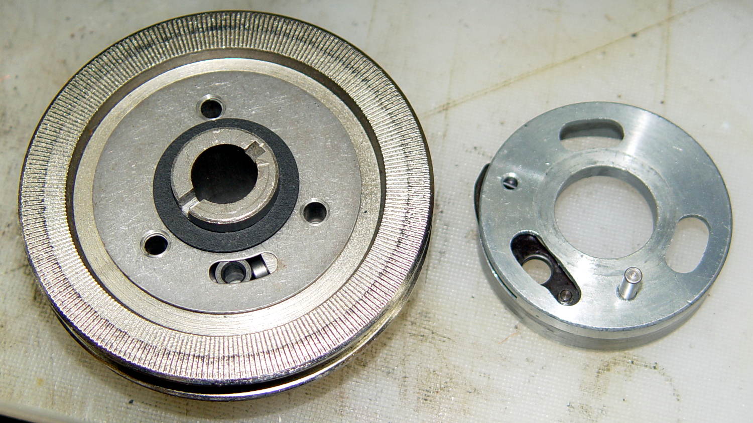
    Remove the fiber washer and the steel cover plate to expose the clutch mechanism:

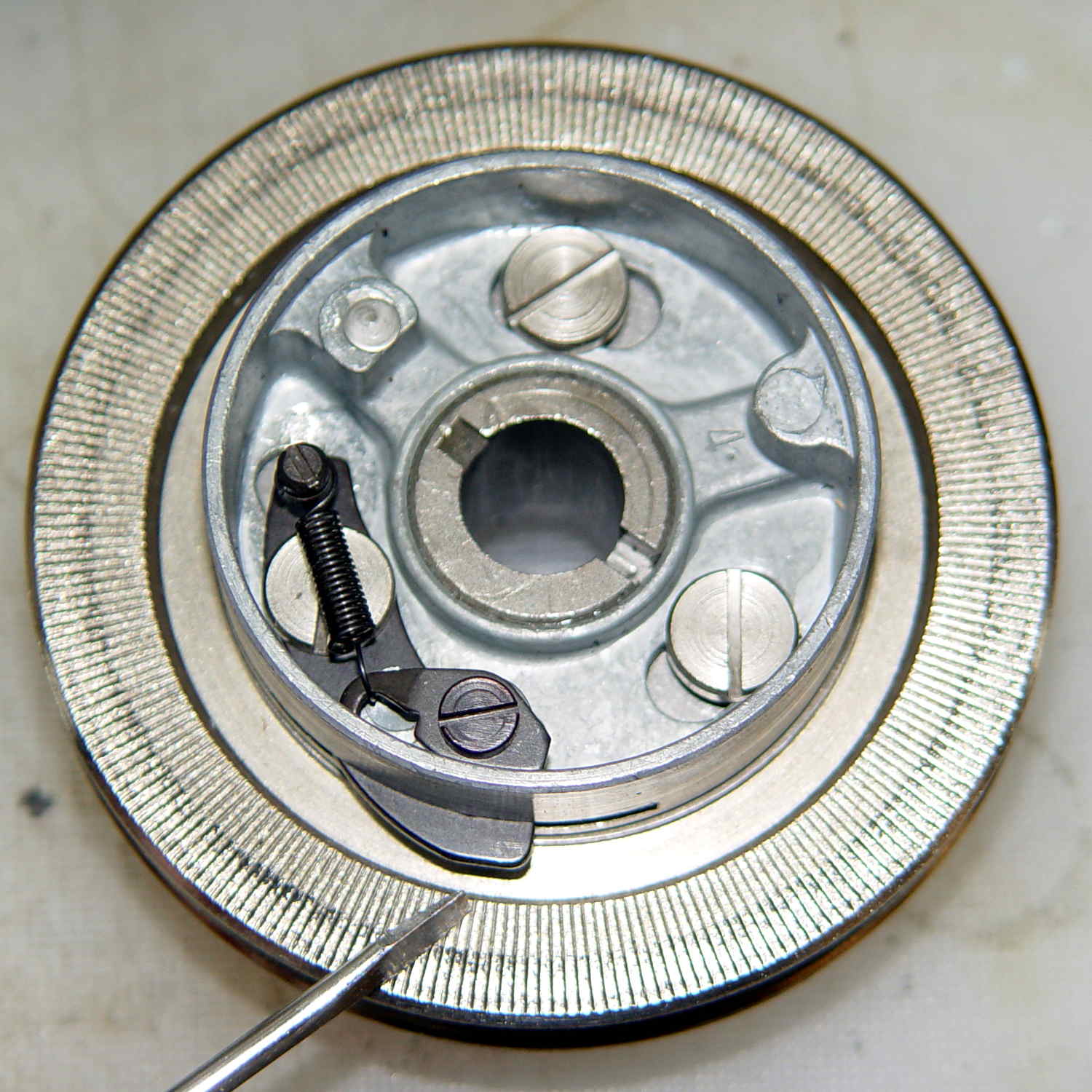
    Kenmore 158.17032 - Handwheel clutch - detail
    Kenmore 158.17032 – Handwheel clutch – detail

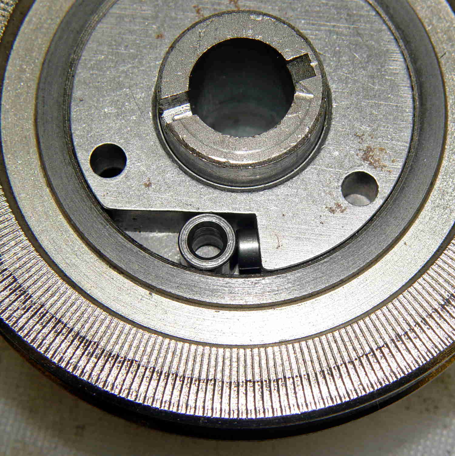
    The pin pressing against the hollow cylinder (which is the actual clutch!) has a powerful spring:

    Kenmore 158.17032 - Handwheel clutch interior
    Kenmore 158.17032 – Handwheel clutch interior

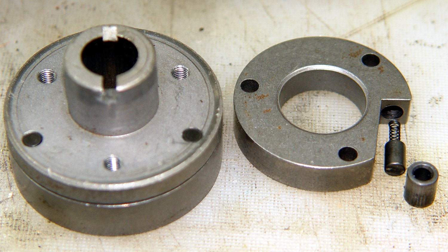
    If you hold the cylinder in place, you can rotate the clutch body enough to unload the spring just enough to let you ease the cylinder out and gently release the spring. Good luck!

    With all the parts on the bench, clean everything, lube only the parts that need it (like the spring-loaded pin, but not the clutch cylinder), put everything back together, and it should Just Work.

    The screwdriver points out the tab engaging the black bow-tie doodad:

    Kenmore 158.17032 - Handwheel clutch tab
    Kenmore 158.17032 – Handwheel clutch tab

    The object of the games is to make the tab pivot smoothly around the large flat-head screw under the spring as you press the part that sticks out, so the clutch will be either completely disengaged or firmly engaged.

    When you get it working smoothly, release the brake bands, slide the clutch assembly back on the shaft, reinstall the cover, install the handwheel, install the screw, pop the plastic hub back in, and you’re done!

    Update:

    Even though I write this stuff down to help me remember what I did, sometimes other folks find it useful:

    Just read your article about Kenmore 158.17032 Handwheel clutch and was able to repair a machine because of you. I so appreciate that you take the time to post such things. I would not have taken the thing apart had I not found your article and I just wanted to say THANKS. I browsed some of your other projects also. Wow.

    Thanks Again,
    Donnie

    … and …

    I have spent weeks searching for how to fix the Kenmore 158.1703 clutch ( a very weird one) for a friend of mine. I was pointed to your post by the Vintage Kenmore sewing machine groups.io.
    I jumped up and down with joy to read and see the photos.
    Yes! I can fix this and get it back to her. THANK YOU! I will try later today with your post printed out.
    Thank you!
    Linda

    More small victories in the struggle against entropy!

    The Kenmore Vintage Sewing Machine group may come in handy.