Ed Nisley's Blog: Shop notes, electronics, firmware, machinery, 3D printing, laser cuttery, and curiosities. Contents: 100% human thinking, 0% AI slop.
One of Mary’s quilting group arrived with a machine in dire need of cleaning and oiling. These screws hold the throat plate in place:
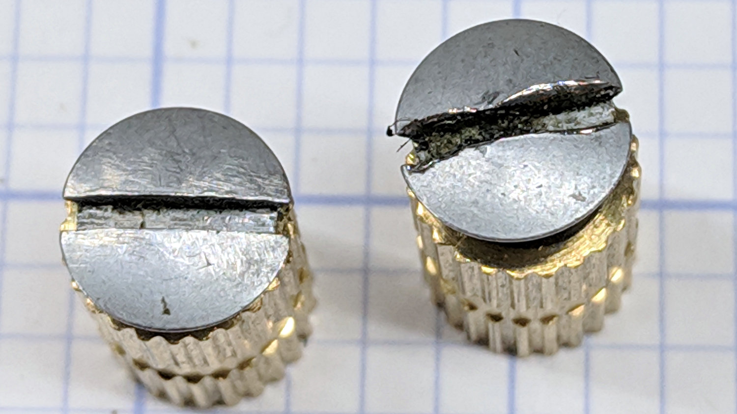
Kenmore screws – goobered
They’re standing in a pair of threaded brass inserts (found in the benchtop litter) to show off their tops.
The left screw came out easily, although a few licks with a fine file eased the slot corners.
The one on the right, however, was firmly jammed in place, with the crappy little Kenmore sewing machine screwdriver causing the goobering. I deployed my Brownell’s Gunsmith Screwdriver Bits, applied slightly less force than would ordinarily call for an overnight penetrating oil session, got the screw out, and cleaned it up:
Kenmore screws – smoothed
A dot of oil on the threads should keep it happy for the foreseeable future.
That’s a staged shot with a quilt square from the top of the pile. You’d (well, Mary’d) sew along the lines, not across a finished square.
The remaining deep shadows under the foot require an LED with an imaging lens on a gooseneck; precise piecing requires feeding fabric into the needle with alignment exactly where those shadows fall.
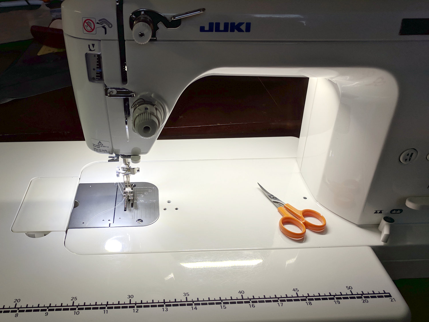
The light levels look harsh and shadowy on the bare base:
Juki TL-2010Q Needle LEDs – front
The shadow extending leftward from the needle comes from the arm’s shadow of the rear LED bar. The hotspot specular reflections of both LED arrays aren’t quite as glaring in real life, but a matte surface finish would be better.
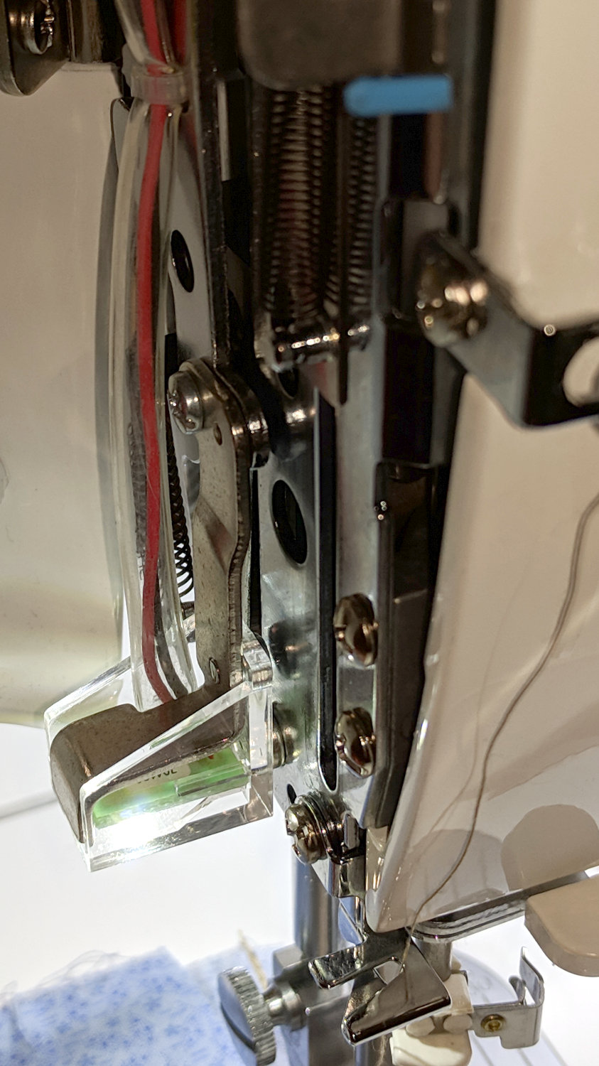
The needle LEDs sit on the bottom of the heatsink inside the endcap:
Juki TL-2010Q Needle LEDs – installed
The COB LED PCB has a weird pink tint, perhaps due to the silicone filter passing all the yellow and blue light downward, with red light reflected into the PCB.
After one iteration, I settled on a 20 Ω 1 W ballast resistor:
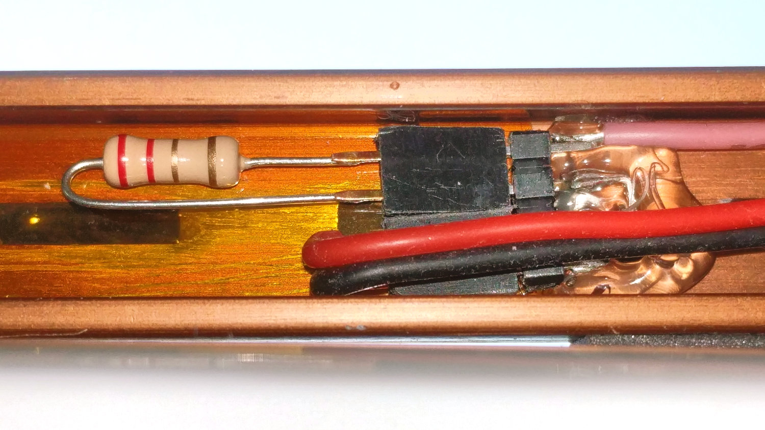
Juki TL-2010Q Needle LEDs – ballast resistor
It drops 3.6 V to provide 180 mA of needle LED current and dissipates 640 mW, with the LEDs burning about 1.5 W to raise the heatsink just above room temperature. The extrusion on the rear arm is pleasantly warm and the resistors seem happy enough.
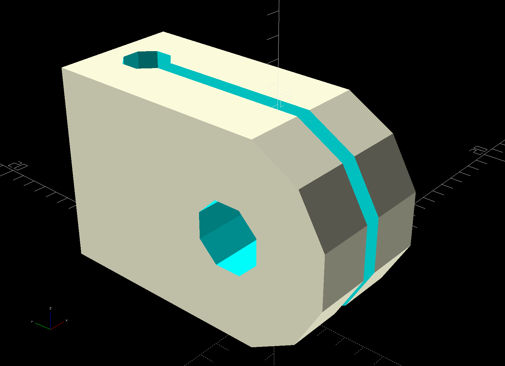
Ream out the holes with suitable drills, clean out the slot using Tiny Bandsaw™, and it’s all good.
In retrospect, the slot isn’t worth the effort, because it doesn’t open wide enough to admit the cable and doesn’t provide any clamping force; a simple block with two holes would do as well. If the heatsink didn’t already have a 3 mm screw in play, I’d use an adhesive-backed clip from the early Kenmore LEDs.
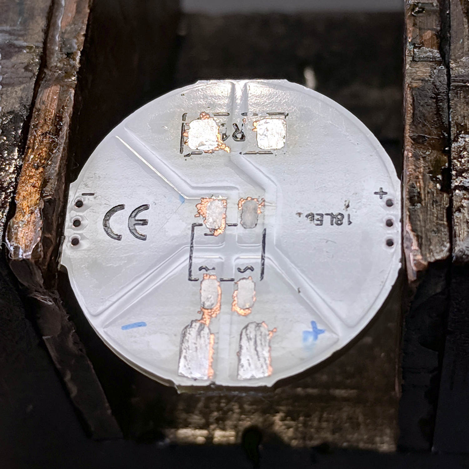
Stripping the components from the back of a “5 W” COB LED gets it ready for action:
G4 COB LED PCB – stripped
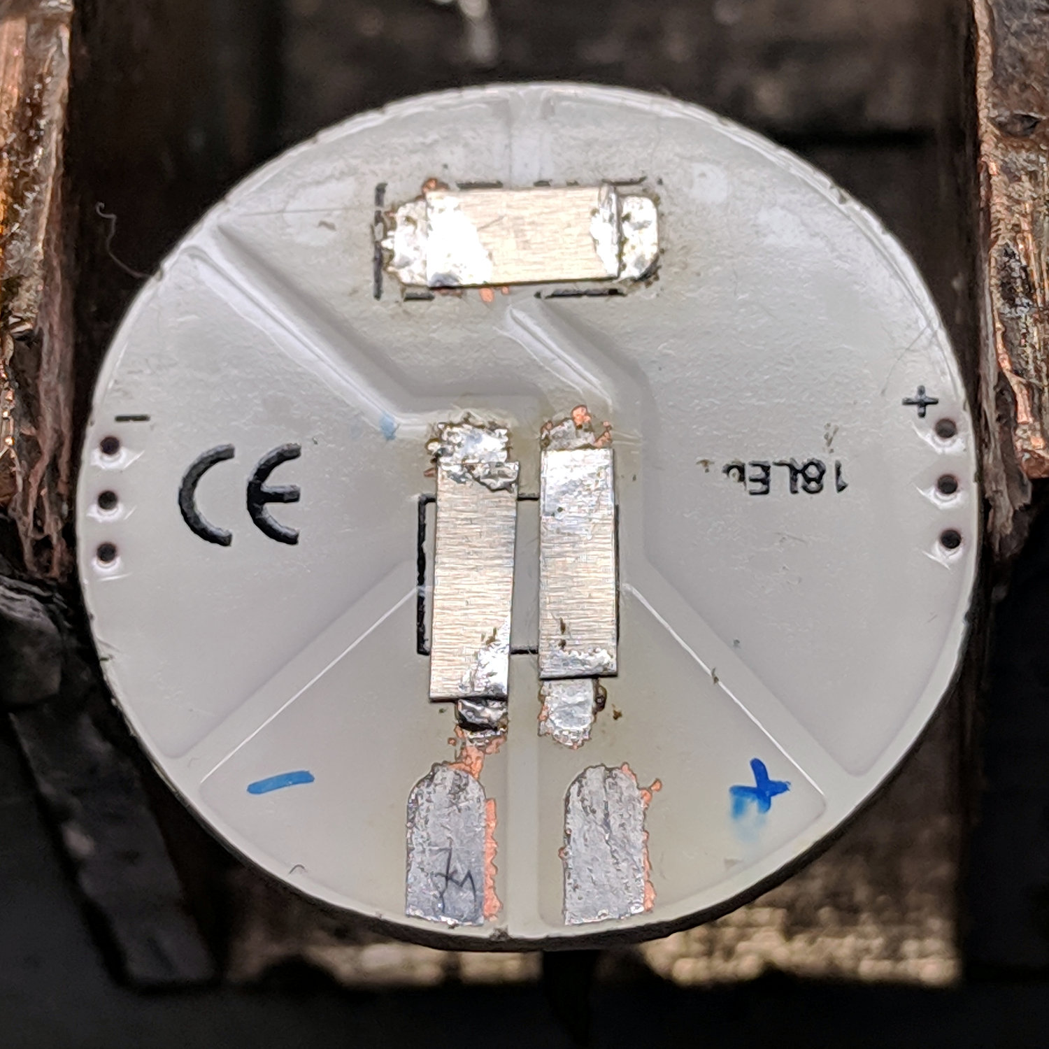
Jumpering the pads with nickel strips harvested from various NiMH and lithium cells restores the original contact pads to service:
Juki TL-2010Q Needle LEDs – COB LED jumpers
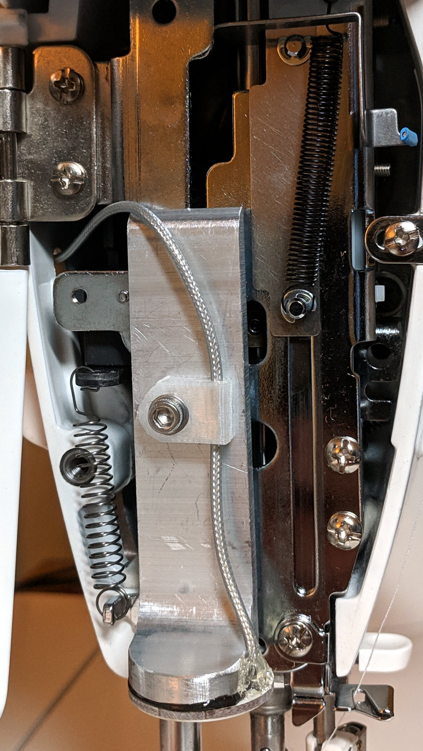
A bit of bandsaw artistry produced a replacement for the OEM LED bracket:
Juki TL-2010Q Needle LEDs – trial installation
The epxoy bonding the LED to the heatsink happens a few paragraphs ahead in this story, but the view justifies it. The 2 mm hole just to the right of the 3 mm SHCS aligns the heatsink to a pin in the machine’s frame, ensuring it doesn’t twist around under vibration.
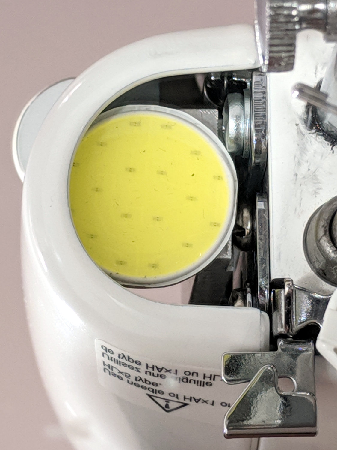
The view from below (in a mirror on the machine’s bed) shows the COB LED just barely fits in the opening:
Juki TL-2010Q Needle LEDs – trial fit
I screwed the bare heatsink into the Juki, applied double-stick tape to the COB LED, aligned LED with opening, and stuck it in place. Back in the shop, I traced around the LED to figure out what part of the heatsink needed removing, introduced it to Mr Disk Sander, and contoured it to match the LED.
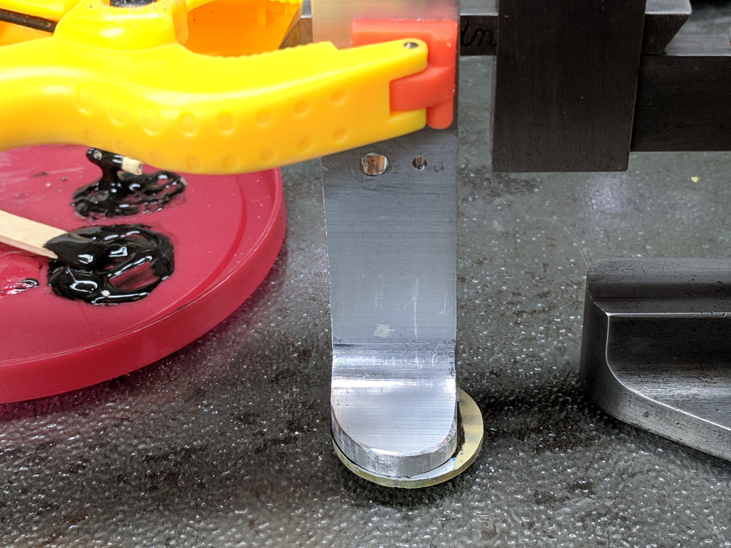
Clean everything with denatured alcohol, put the heatsink on a glass plate, and clamp it to the height gauge:
Juki TL-2010Q Needle LEDs – heatsink alignment
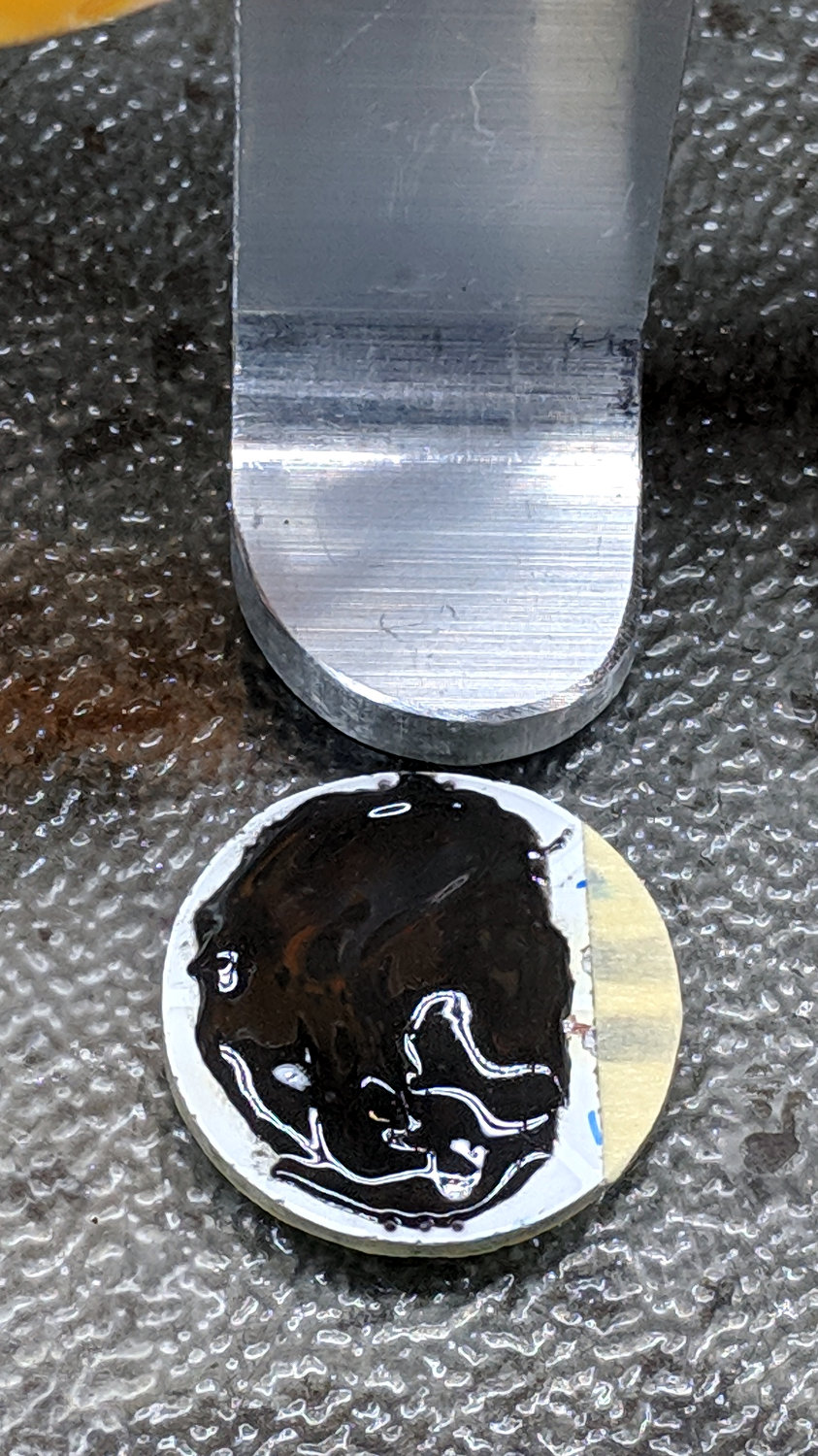
Butter up the LED PCB with JB Kwik epoxy, having previously masked the contact pads (with masking tape!) to prevent oopsies:
Juki TL-2010Q Needle LEDs – epoxy on COB LED
Raise the height gauge, align LED & heatsink, lower height gauge to squish epoxy into an even layer, raise slightly to ensure the aluminum heatsink doesn’t short the nickel strips, and fast forward a few hours:
Juki TL-2010Q Needle LEDs – heatsink curing
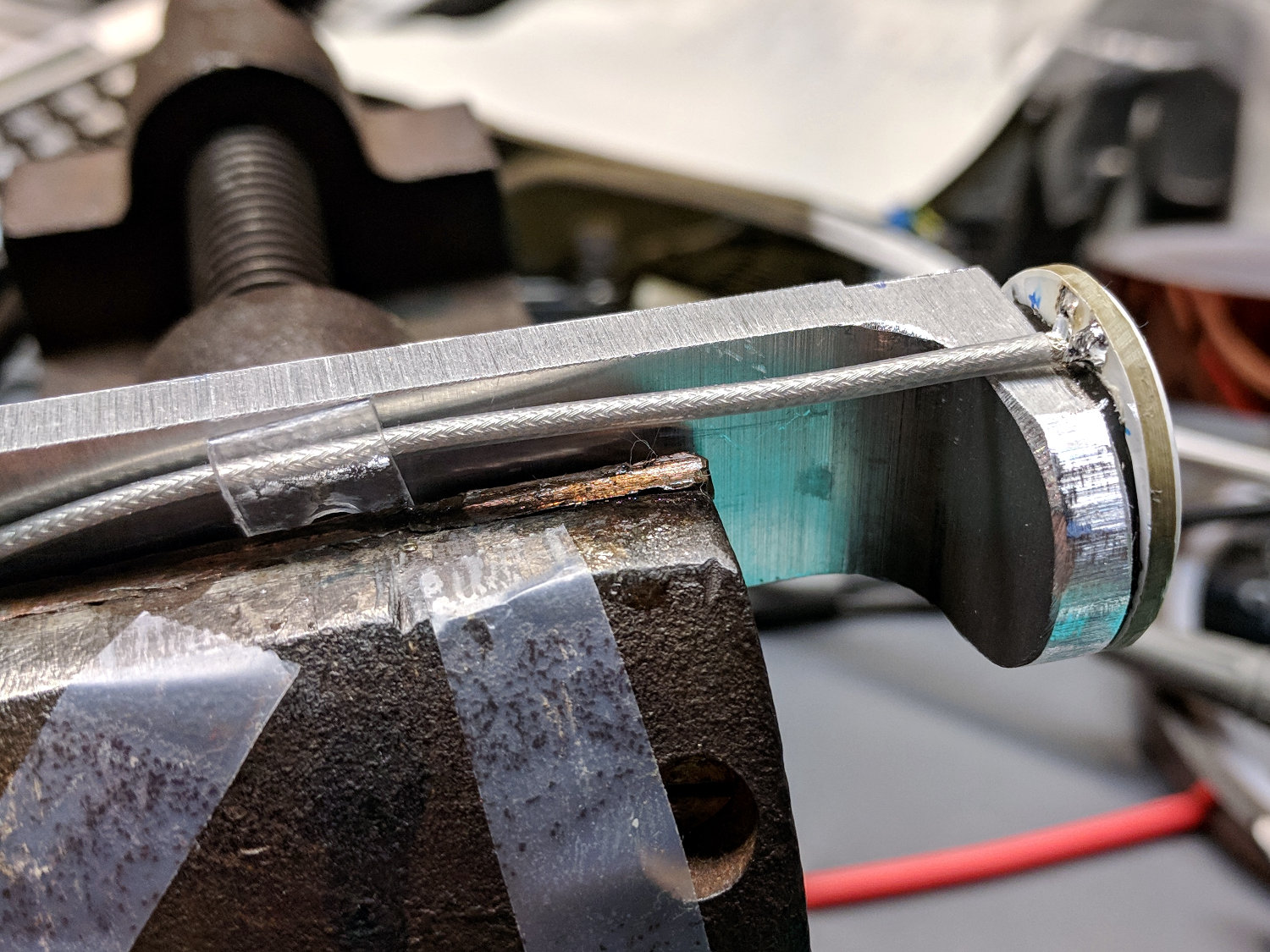
Peel off the masking tape and solder a cable in place:
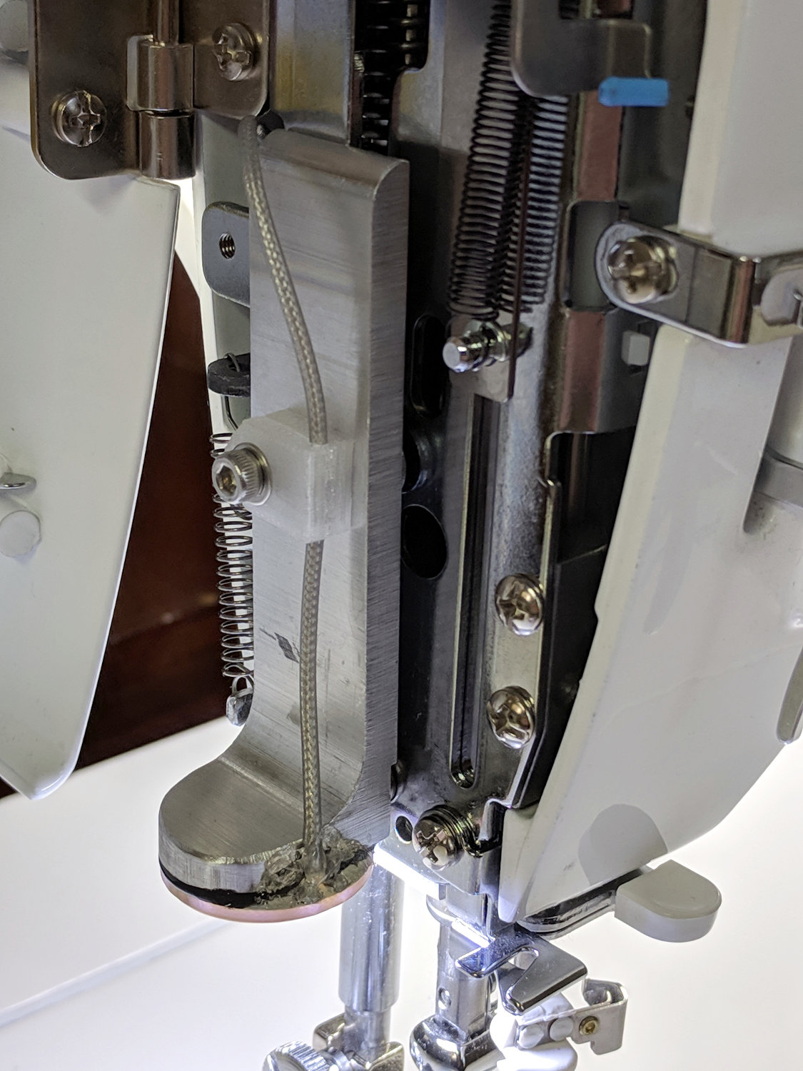
Juki TL-2010Q Needle LEDs – cable installation
The transparent doodad around the cable is a PET clamp snipped from a consumer electronics clamshell package, then punched and folded to suit. It didn’t work particularly well, so more rummaging will be required.
Foreshadowing: all this went swimmingly and looks pretty good (in a techie sort of way), but I’ve been running a nasty cold (stipulated: there being no pleasant colds). Building While Stupid is never a good idea, as the part of your brain in charge of telling you you’re about to do something catastrophically wrong is the first thing to go.
After more use and brightness tweaking, the COB light bars on the Juki TL-2010Q and Kenmore 158 now have 2.2 Ω ballast resistors setting the LED current to 370 mA and 300 mA, respectively:
Juki TL-2010Q COB LED – 2.2 ohm header
Changing from 2.0 Ω to 2.2 Ω produces a noticeable decrease in light, so 10% steps around 2 Ω seem to be about the right increment. The COB LED strips claim 6 W at 12 V = 500 mA nominal, so they’re running well under the spec.
A bag of G4 COB LEDs arrived from halfway around the planet:
G4 COB LEDs – 15 and 18 LED modules
Those are “5 W” and “4 W” cool white modules, respectively, with another set of 4 W warm white looking pretty much the same. There’s no provision for heatsinking, which makes the wattage seem suspect; halogen G4 bulbs run around 20 W, for whatever that’s worth.
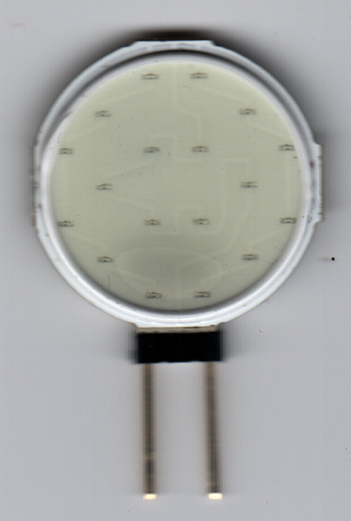
The silicone overlay becomes nearly transparent when seen through an ordinary desktop document scanner:
Circular 12V COB 18 LED panel
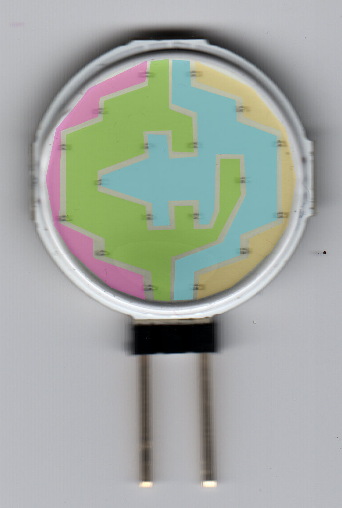
Highlighting the PCB copper pours shows 18 LEDs arranged in three series groups of six LEDs in parallel:
Circular 12V COB 18 LED panel – copper layout
The “smart IC” touted in the writeup turns out to be a bridge rectifier for AC or DC power:
G4 COB LED – 18 LED – components
The SMD resistors on all 15 modules measure 27.6 Ω, more or less, and seem randomly oriented face-up or face-down. I assume that one is face-down; maybe it’s just unlabeled on both sides.
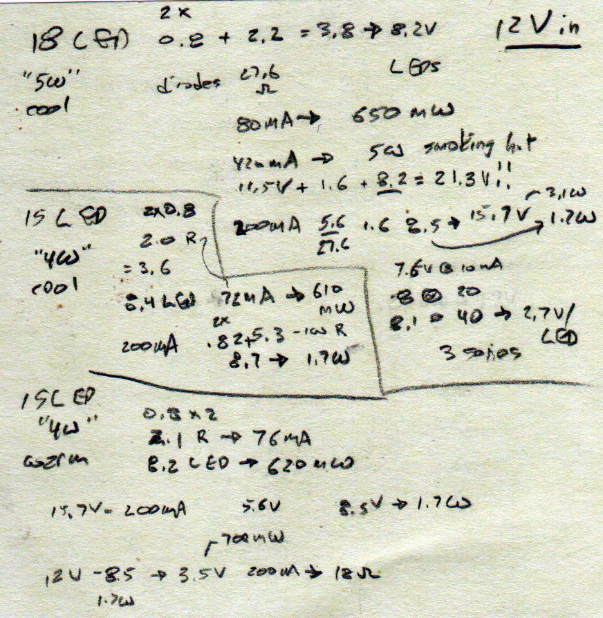
Back of the envelope: there’s no way it will dissipate 5 W. The bridge drops 1.4 V = 2×0.7, the LEDs drop maybe 9 V, leaving the resistor with 1.6 V to pass all of 60 mA, so call it 700 mW.
Some measurements:
G4 COB LED measurements
With 12 VDC applied to the pins, the bridge drops 1.6 V, the LEDs 8.2 V, and the resistor 2.2 V, with 80 mA through the whole affair dissipating just under 1 W.
Huh.
Cranking the supply until the current hits 200 mA puts 15.7 V across the pins for a total dissipation of 3.1 W, burning 1.7 W in the LEDs and 1.1 W in the resistor.
Cranking the supply to 21.3 V drives 410 mA, dissipates just under 9 W total, produces a curl of rosin smoke from the PCB, and maybe delaminates the silicone around some of the LEDs.
OK, now I have a crash test dummy.
Given complete control over the application, I’ll strip everything off the PCB and bond it to a heatsink of some sort. With 6 LEDs in parallel, 120 mA (6 × 20 mA) total current might be reasonable and 200 mA (6 × 30 mA) probably won’t kill the things outright. Plus, I have spares.
An external 18 Ω resistor should suffice. Perhaps a pair of 6 Ω SMD resistors on the PCB, with fine-tuning through an external resistor. Call it 250 mW apiece: don’t use little bitty SMD resistors.