It Has Been Decided (in that place where what is decided must be) to allow a single hole in the sewing machine’s front panel:
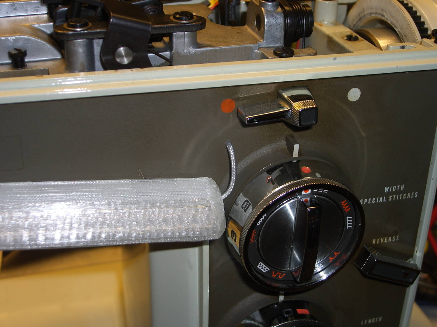
The hole barely passes the 2 mm coaxial cable I’m misusing for the LED strips and is located where it:
- Clears the machine’s metal frame to the upper left
- Isn’t blocked by the knob’s mounting bracket to the lower right
- Doesn’t snag the knob’s cam followers all over the insides
- Lines up directly below the orange dot for pretty
The first three of those happen behind the front panel, inside the frame, where you (well, I) can neither see nor measure the locations. I used a large outside caliper to get a feel for where the hole could possibly fit, then got it right on the first try!
On the rear panel, it turns out that the presser foot lever doesn’t quite touch the top of its slot in the frame, so the cable for those LED strips can sneak through:

Just inside that slot, the cable turns right, passes into the endcap, then goes upward to re-emerge at the top, inside the channel used for the old 120 VAC zip cord that powered the incandescent bulb in the endcap.
I had some square cable clips lying around, so I used them, but the (yet to be designed) round versions will look better.
The grody frame tells you this is the crash test dummy machine I’m using to verify things before installing them in Mary’s machine.
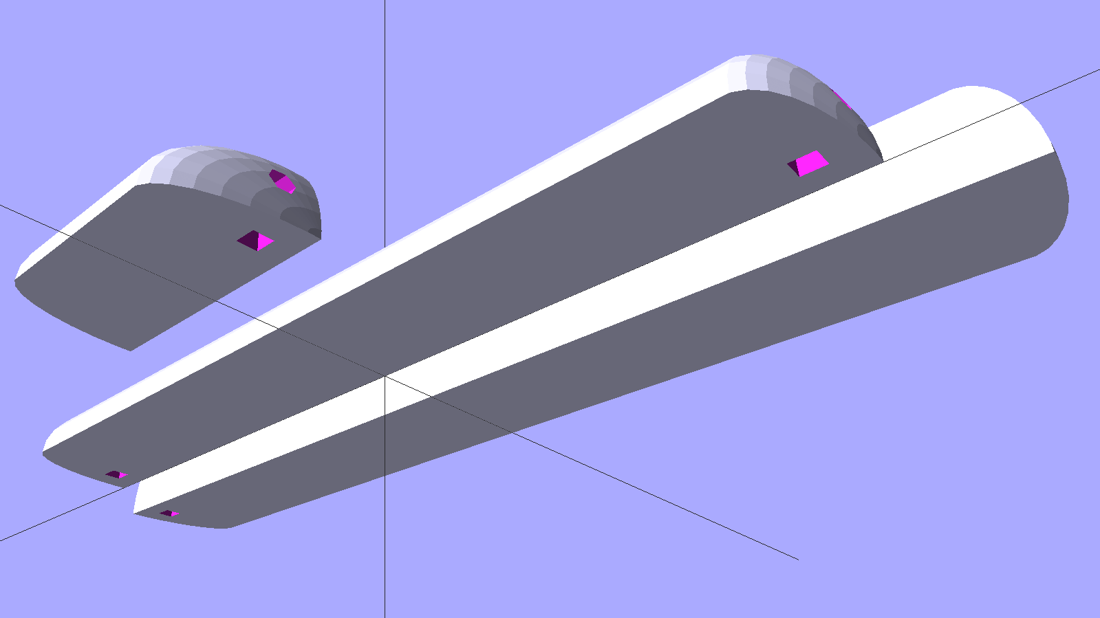
The improved cable routing required different hole positions in the LED strip mounts:
The internal wire route follows the original 120 VAC zip cord’s route from the bottom of the machine to the endcap (on the left), with the new branch for the front LEDs curving over the main shaft:

The four-conductor ribbon cable also carries the supply voltage for the yet-to-be-built high intensity LED emitters in the end cap that will replace the 10 mm LEDs, with the ends terminated under the clamp in the middle. Those old steel wire clamps seem grossly oversized for the job, but that’s OK with me.
The ribbon cable eases past that whirling crank arm, then passes through the frame to the outside cover under the handwheel, where it just barely clears the drive belts. A few zip ties hold it out of the way.
The OpenSCAD source code offsets the wiring holes by 0.5 mm from the ends of the LED strips for easier wire bending, but is otherwise pretty much the same as before:
// LED Strip Lighting Brackets for Kenmore Model 158 Sewing Machine
// Ed Nisley - KE4ZNU - March 2014
//  October 2014 - tweak endcap length & channel position

Layout = "Build";			// Build Show Channels Strip

//- Extrusion parameters must match reality!
//  Print with 2 shells and 3 solid layers

ThreadThick = 0.20;
ThreadWidth = 0.40;

HoleWindage = 0.2;			// extra clearance

Protrusion = 0.1;			// make holes end cleanly

AlignPinOD = 1.70;			// assembly alignment pins: filament dia

inch = 25.4;

function IntegerMultiple(Size,Unit) = Unit * ceil(Size / Unit);

//----------------------
// Dimensions

LEDSegment = [25.0,10.0,3.0];		//  size of each LED segment
SEGLENGTH = 0;
SEGWIDTH = 1;
SEGHEIGHT = 2;

WireChannel = 3.0;				// wire routing channel diameter

StripHeight = 12.0;				// sticky tape width

DefaultLayout = [1,2,"Wire","NoWire"];
NUMSEGS = 0;
NUMSTRIPS = 1;
WIRELEFT = 2;
WIRERIGHT = 3;

EndCapSides = 8*4;				// endcap smoothness
EndCapShim = 0.5;				// additional space for easier wire bending

function EndCapSize(Layout) = [(2*WireChannel + EndCapShim),Layout[NUMSTRIPS]*LEDSegment[SEGWIDTH],StripHeight];

//----------------------
// Useful routines

module PolyCyl(Dia,Height,ForceSides=0) {			// based on nophead's polyholes

  Sides = (ForceSides != 0) ? ForceSides : (ceil(Dia) + 2);

  FixDia = Dia / cos(180/Sides);

  cylinder(r=(FixDia + HoleWindage)/2,
           h=Height,
           $fn=Sides);
}

module ShowPegGrid(Space = 10.0,Size = 1.0) {

  RangeX = floor(100 / Space);
  RangeY = floor(125 / Space);

	for (x=[-RangeX:RangeX])
	  for (y=[-RangeY:RangeY])
		translate([x*Space,y*Space,Size/2])
		  %cube(Size,center=true);

}

//-- The negative space used to thread wires into the endcap

module MakeWireChannel(Layout = DefaultLayout,Which = "Left") {

	EndCap = EndCapSize(Layout);	// radii of end cap spheroid

	HalfSpace = EndCap[0] * ((Which == "Left") ? 1 : -1);

	render(convexity=2)
	translate([0,LEDSegment[SEGWIDTH]/2,0])
		intersection() {
			union() {
				cube([2*WireChannel,WireChannel,EndCap[2]],center=true);
				translate([-2*EndCap[0],0,EndCap[2]/2])
					rotate([0,90,0]) rotate(180/6)
						PolyCyl(WireChannel,4*EndCap[0],6);
			}
			translate([HalfSpace,0,(EndCap[2] - Protrusion)]) {
				cube(2*EndCap,center=true);
			}
		}
}

//-- The whole strip, minus wiring channels

module MakeStrip(Layout = DefaultLayout) {

	EndCap = EndCapSize(Layout);	// radii of end cap spheroid

	BarLength = Layout[NUMSEGS] * LEDSegment[SEGLENGTH];				// central bar length

	echo(str("Strip OAL: ",BarLength + 2*EndCap[SEGLENGTH]));

	hull()
		difference() {
			for (x = [-1,1])						// endcaps as spheroids
				translate([x*BarLength/2,0,0])
					resize(2*EndCap) rotate([0,90,0]) sphere(1.0,$fn=EndCapSides);
			translate([0,0,-EndCap[2]])
				cube([2*BarLength,3*EndCap[1],2*EndCap[2]],center=true);
			translate([0,-EndCap[1],0])
				cube([2*BarLength,2*EndCap[1],3*EndCap[2]],center=true);
		}

}

//-- Cut wiring channels out of strip

module MakeMount(Layout = DefaultLayout) {

	BarLength = Layout[NUMSEGS] * LEDSegment[SEGLENGTH];

	difference() {
		MakeStrip(Layout);
		if (Layout[WIRELEFT] == "Wire")
			translate([(BarLength/2 + EndCapShim),0,0])
				MakeWireChannel(Layout,"Left");
		if (Layout[WIRERIGHT] == "Wire")
			translate([-(BarLength/2 + EndCapShim),0,0])
				MakeWireChannel(Layout,"Right");
	}
}

//- Build it

ShowPegGrid();

if (Layout == "Channels") {
	translate([ (2*WireChannel + 1.0),0,0]) MakeWireChannel(DefaultLayout,"Left");
	translate([-(2*WireChannel + 1.0),0,0]) MakeWireChannel(DefaultLayout,"Right");
}

if (Layout == "Strip") {
	MakeStrip(DefaultLayout);
}

if (Layout == "Show") {
	MakeMount(DefaultLayout);
}

if (Layout == "Build") {

	if (false) {					// original no-drill wiring
		translate([0,(3*LEDSegment[SEGWIDTH]),0]) MakeMount([1,2,"Wire","Wire"]);		// rear left side, vertical
		translate([0,0,0]) MakeMount([5,2,"Wire","NoWire"]);				// rear top, across arm
		translate([0,-(3*LEDSegment[SEGWIDTH]),0]) MakeMount([6,2,"NoWire","Wire"]);	// front top, across arm
	}

	if (true) {						// front: drill panel, rear: route through foot lift lever
		translate([0,(3*LEDSegment[SEGWIDTH]),0])
			MakeMount([1,2,"NoWire","Wire"]);				// rear left side, vertical
		translate([0,0,0])
			MakeMount([5,2,"Wire","Wire"]);					// rear top, across arm
		translate([0,-(1*LEDSegment[SEGWIDTH]),0])
			rotate(180)
			MakeMount([6,2,"NoWire","Wire"]);				// front top, across arm
	}
}

Comments
2 responses to “Kenmore 158 LED Strip Lighting: Now With Improved Wiring!”
[…] read more on: softsolder.com […]
[…] in a bag until I install the new LED strips and needle […]