The first pass at retrofitting SMD LEDs to light the needle area in Mary’s Model 158 sewing machine worked well enough:
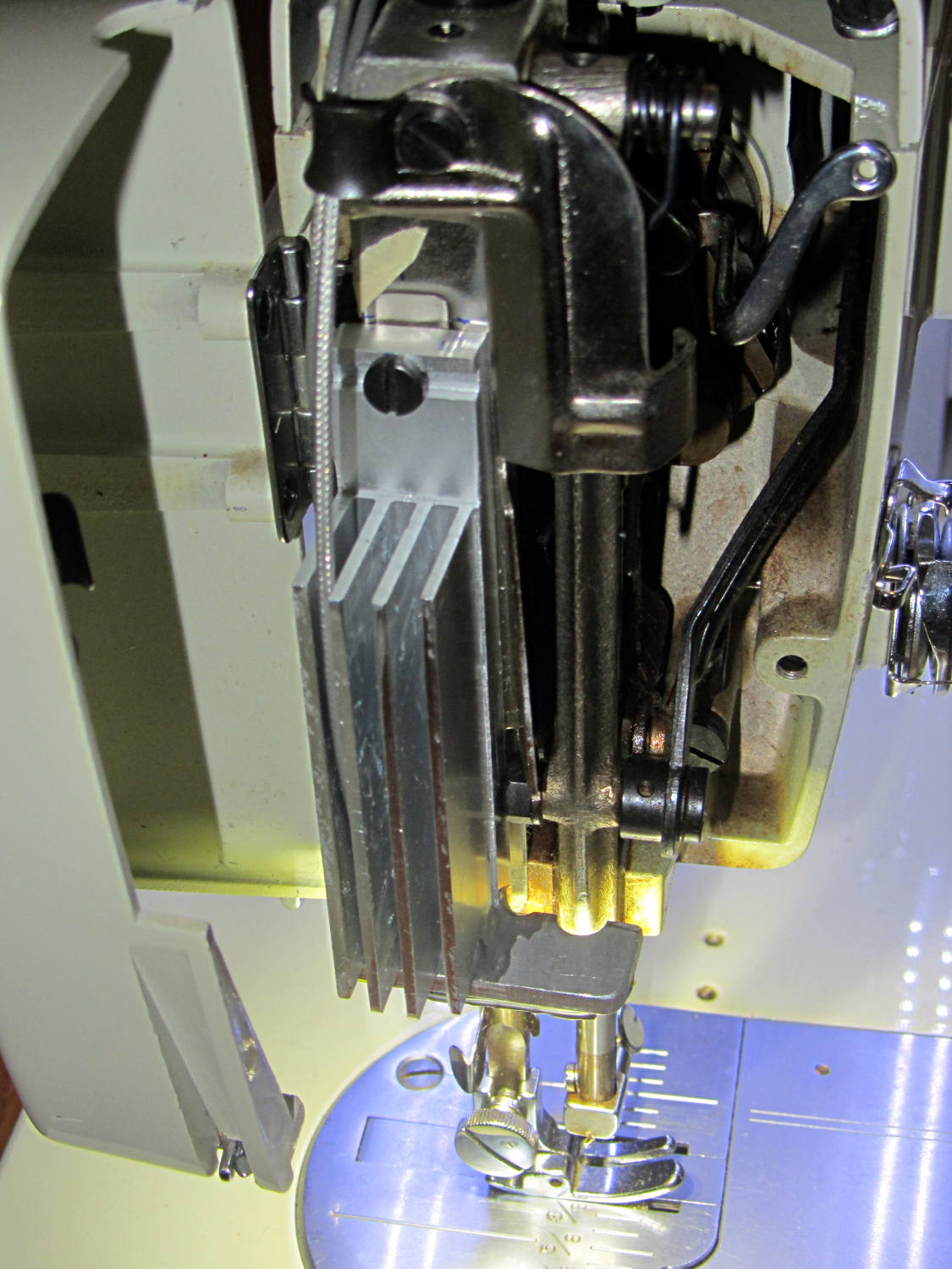
However, she wanted more light on the right side of the needle, so now she has it:
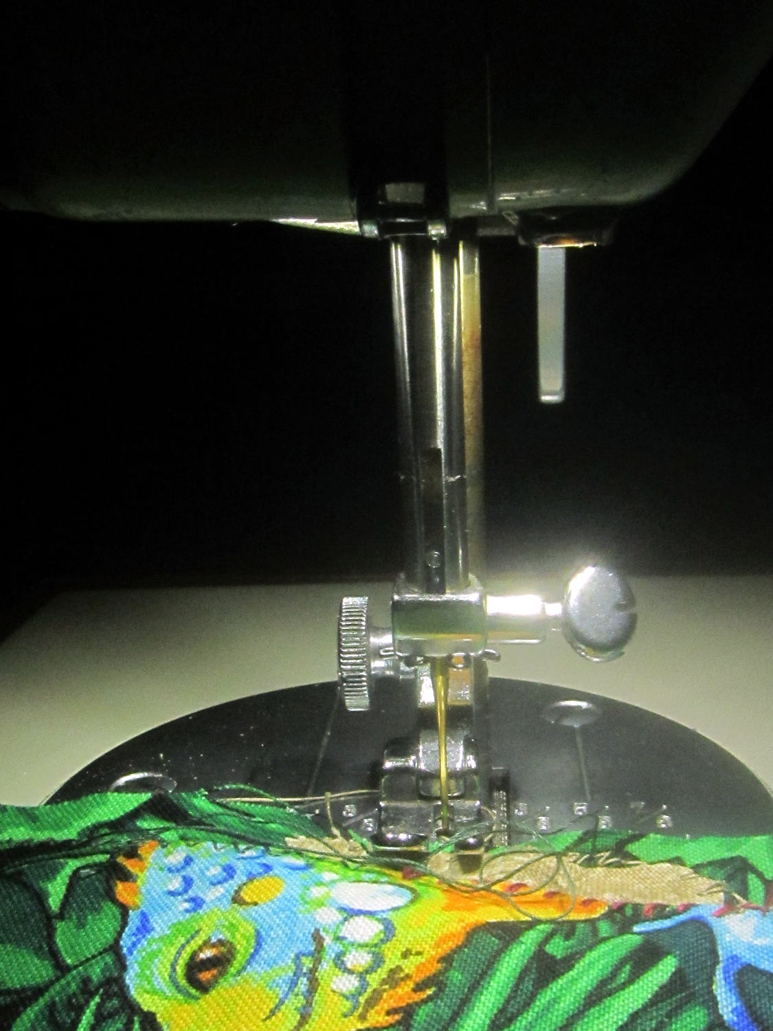
That’s without any LEDs along the front and back of the arm, hence the dark pool beyond the sewing machine’s base.
Those are the same 5050 warm white LEDs I used on the other side:
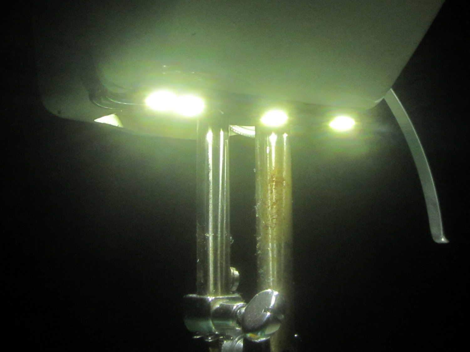
Seen without the glare:
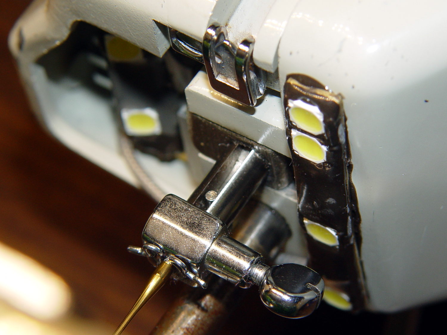
They’re mounted on a 32 mil brass strip from the shimstock stash, carefully hand-bent and twisted to match the curvature of the arm, and held in place with JB Kwik steel-filled epoxy for good heat conduction to the aluminum arm. One can argue with the epoxy oozing out from under the brass, but it’s invisible from above.
No construction photos, alas, because I made this in a white-hot frenzy one afternoon and managed to not take any pix during the entire session. Call it working in the flow, OK?
All four SMD LEDs sit in epoxy blobs that isolate them from the brass strip, with 26 AWG solid wire “bus bars” soldered to the top of their terminals and a length of that lovely PTFE-insulated miniature coax leading off into the endcap. More epoxy encloses all the wiring & connections to provide a surprisingly smooth surface that shouldn’t snag the fabric.
The power supply uses an 18 W 120 VAC to 12 VDC brick intended for small LED installations:
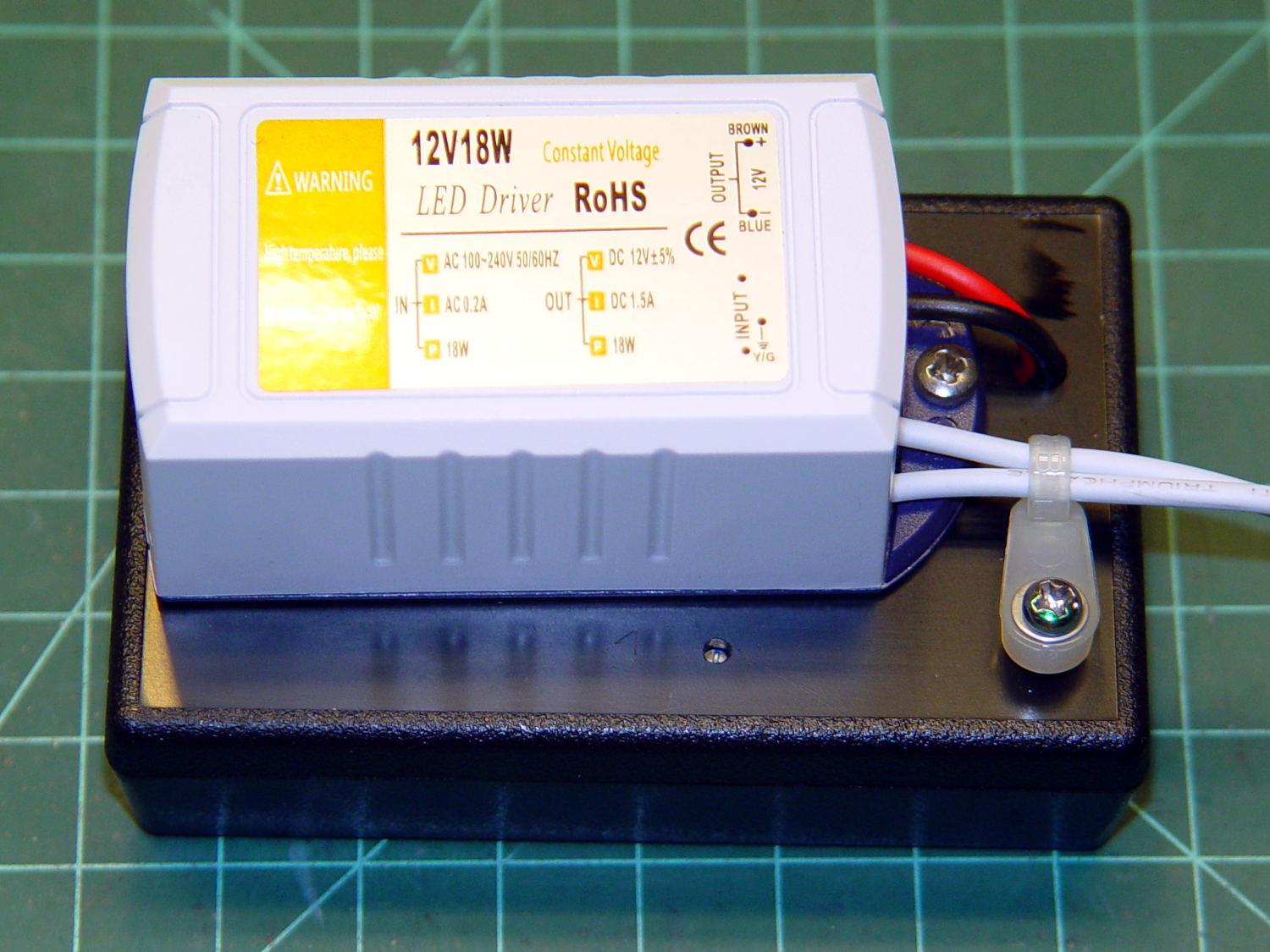
The AC comes from the same zip cord that formerly supplied the original 15 W incandescent bulb in the endcap, so the new lights behave the same way: push the power button to turn on the machine and the LEDs pop on just like they should. I put quick-disconnect terminals in the AC line to make it removable, although those need some sort of insulated plug to cover the exposed blades inside their housing.
Inside the black box, a small boost supply steps the voltage up to just under the nominal operating level of 21 VDC:
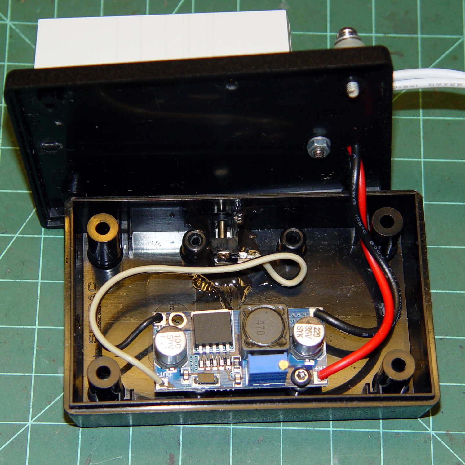
You can just see the adjusting screw hole in front of the AC brick in the overall view.
The DC output exits in the middle of the far side, through a coax jack epoxied to the base.
As before, all six LEDs run in parallel at (for now) 18.5 VDC and maybe 50 mA each, for a total of 300 mA, and seem fearsomely bright even at that. We can now tune for best light as needed.
This is a major major major improvement over the previous tangle of wires stuck on the outside of the machine, with all the wiring internal to the arm and the power supply out of sight under the sewing table.
After an hour, the arm above the four LEDs runs 13 °C above ambient and the endcap over the two LED heatsink is 6 °C over ambient. The AC supply runs at 104 °C and its plastic case offers no provision for heatsinking. All in all, things are warm and not hazardous.
I haven’t retrofit this machine with LED strips along the front & back of the arm, as those may not be needed with the intense needle lighting; the NisLite desk lamp may suffice for area illumination.

Comments
4 responses to “Kenmore Model 158: Needle Lights, Now With Moah LEDs”
As a great fan of simple solutions, I pose this question. What might be expected if you used a simple 24vac doorbell transformer instead of all this electronics? (Add a dropping resistor if you like.)
Doorbells run on AC, but the LEDs need DC, which requires a (bridge) rectifier and (big) filter cap. Because the voltage wouldn’t come out right, you’d also need a fairly high-power ballast resistor, chosen for the proper brightness, with enough ventilation to keep it cool.
The 12 V supply was $4 and the boost supply was just over $1. Both are switchers, neither requires active cooling, and there’s a twiddlepot to adjust the brightness.
That’s really about as simple as it can be: two parts plus a surplus box and I’m done!
Educate me, please. I figured that an LED powered with 60~ ac would flicker at such a fast rate it would appear to be steadily “on.” An LED is a diode… would it be damaged by the half-sine of reversed polarity?
The LEDs would turn off during alternate half-cycles, causing terrible strobe effects on the moving needle: think of spoked wagon wheels in those old spaghetti western movies. Running the LEDs from full wave rectified AC would help, but they’d still strobe at 120 Hz and would be worse than fluorescent tubes because the yellow phosphor reacts faster.
The datasheet sayeth: “This product should be operated in forward bias. A driving circuit must be designed so that the product is not subjected to either forward or reverse voltage while it is off. In particular, if a reverse voltage is continuously applied to the product, such operation can cause migration resulting in LED damage.”
Basically, you shouldn’t run LEDs from AC: they’re diodes that emit light, but they’re such crappy diodes that you can’t use them for rectification.