The Smell of Molten Projects in the Morning

Ed Nisley's Blog: Shop notes, electronics, firmware, machinery, 3D printing, laser cuttery, and curiosities. Contents: 100% human thinking, 0% AI slop.

Tag: Sewing

Fabric arts and machines

  • Kenmore 158 Sewing Machine: Hardware Deglaring

    The matte mailing labels on the Kenmore 158’s hand hole cover plate did such a good job reducing the glare from the additional LEDs as to make the shiny hardware around the needle seem overly bright. I suggested gentle sandblasting might improve the situation without changing any surfaces in contact with the fabric.

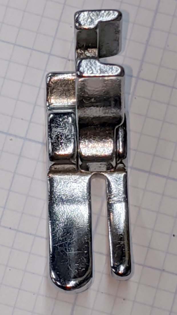
    I was given a spare presser foot to demonstrate my case:

    Kenmore 158 Presser Foot - original - front
    Kenmore 158 Presser Foot – original – front

    The overhead light in the shop produces glare from the nice, shiny steel surfaces similar to what Mary sees from the sewing machine.

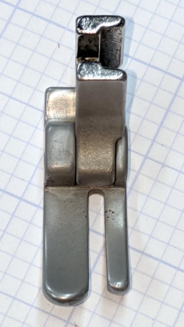
    A few minutes applying 220 grit blast media with Tiny Sandblaster™ definitely changed its appearance:

    Kenmore 158 Presser Foot - sandblasted - front
    Kenmore 158 Presser Foot – sandblasted – front

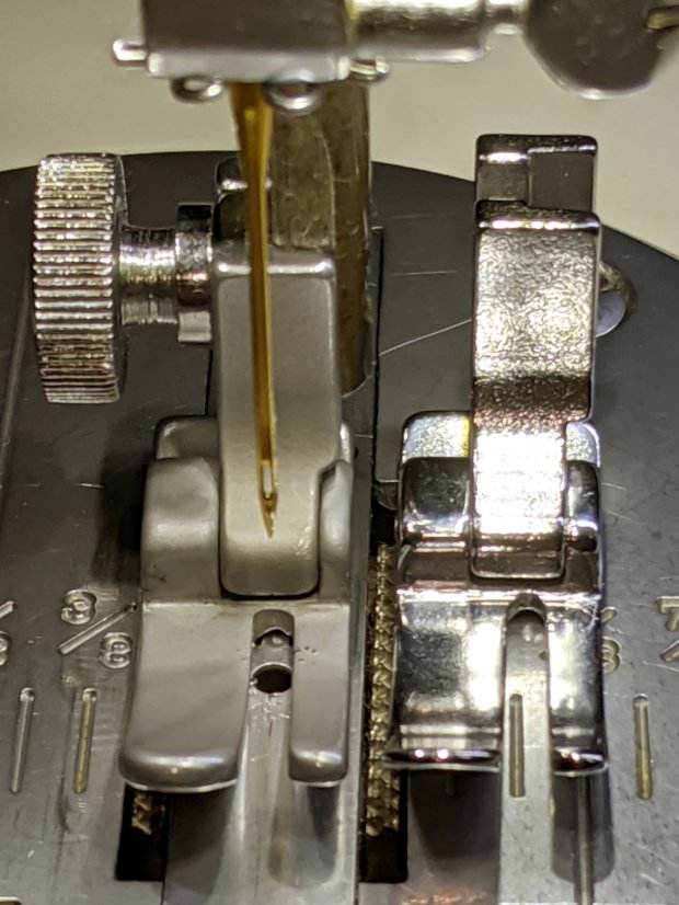
    In person, the finish is neutral gray overall, with those odd brown areas appearing only in photographs, perhaps due to the various lights in the shop. The slight texture variations seem to correspond to minor differences in the plating (?) over the steel surface. It definitely cuts down the glare:

    Kenmore 158 Presser Foot - sandblasted vs original
    Kenmore 158 Presser Foot – sandblasted vs original

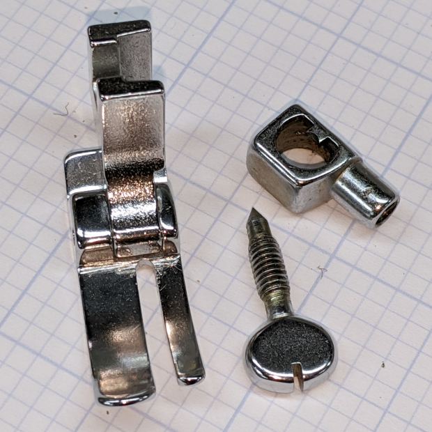
    The needle clamp and screw across the top of that picture travel up and down, so we decided to deglare them along with the “good” foot:

    Kenmore 158 - foot with needle clamp - original
    Kenmore 158 – foot with needle clamp – original

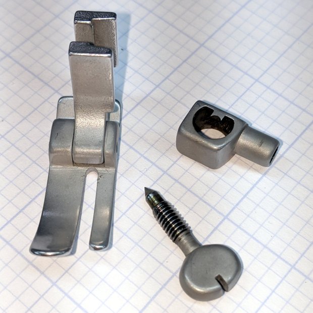
    Another Tiny Sandblaster™ session knocked back their shine:

    Kenmore 158 - foot with needle clamp - sandblasted
    Kenmore 158 – foot with needle clamp – sandblasted

    Those parts came out slightly less matte, perhaps due to reduced pressure in the propellant can. Seeing as how I’ve had the sandblaster for a couple of decades, I figured it’s time to use the propellant but, as expected, the in-can valve doesn’t re-seal properly, so I’ll be using compressed air the next time around.

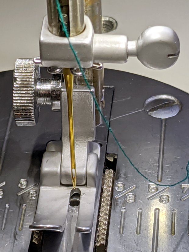
    After rinsing and blowing and rinsing and blowing the grit out of the threads, everything went back together as expected:

    Kenmore 158 - sandblasted hardware installed
    Kenmore 158 – sandblasted hardware installed

    I’m not doing either of the plates until we have more experience with the matte hardware, but it looks pretty good to me.

  • Kenmore 158 Sewing Machine: Glare Reduction

    The additional LEDs around the needle on (one of) Mary’s Kenmore Model 158 sewing machines provide plenty of light for normal sewing, but produced too much glare on the polished steel “hand hole cover plate” (their nomenclature) for small-scale work. A matte surface seemed in order, which came from some translucent mailing labels left over from our Christmas card effort:

    Kenmore 158 - non-glare cover plate
    Kenmore 158 – non-glare cover plate

    Mailing labels probably aren’t a permanent solution, but they certainly solved the problem without delay. We’re loathe to etch the steel, as increasing the surface roughness definitely isn’t what you want, nor blacken it, for obvious reasons.

    Too much light is definitely better than too little, though.

  • Kenmore Model 158: Foot Pedal Pivots

    I got an email asking how the Kenmore Model 158 sewing machine’s foot pedal pivots worked. The notes on rebuilding the carbon disk rheostat and conjuring a Hall effect sensor show the innards, but here’s what you need to know to get there.

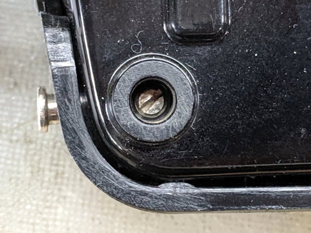
    The pedal has a pair of pivots on the side closest to your foot, held in place with a small screw inside the two feet:

    Kenmore 158 - Pedal pivot screw - in place
    Kenmore 158 – Pedal pivot screw – in place

    The screw fits into a notch in the unthreaded pin inserted from the side:

    Kenmore 158 - Pedal pivot screw - disassembled
    Kenmore 158 – Pedal pivot screw – disassembled

    And that’s all there is to it!

    Now, as happened to my correspondent, the pin can go missing, perhaps after the screw worked loose. Worst case, you’re looking at replacing both parts.

    Being made in Japan (as ours were), the pedal has metric sizes: the unthreaded pin is 4 mm in diameter and 18 mm long and the setscrew has an M4×0.7 thread. You could replace the pin with an 18 mm (down to maybe 15 mm) long M4 screw. The threads would make a gritty pivot, but better than no pivot at all.

    Better to get a longer M4 screw with an unthreaded section near the head, hacksaw it to the proper length, file to tidy up the cut end, maybe file a notch for the setscrew, and pop it in place. For tidiness, file off the slot / Philips / hex socket to eliminate the temptation to turn it out.

    Worst case, a pair of plain old USA-ian 6-32 screws 3/4 inch long would make a sloppy fit. Don’t tell anybody I said so; that’d be barely better than nothin’ at all in there.

    Lowe’s claims to have M4×0.7 setscrews (with a hex socket, not a slot) to secure the pin.

    If my experience around here is any guide, however, Lowe’s / Home Depot / Walmart may claim to have metric hardware in stock, but the only way to know is to actually go there and rummage around in the specialty hardware section, inside the big steel cabinet with slide-out drawers filled with a remarkable disarray of ripped-open bags and misfiled parts.

    Good hunting …

  • Warm-White LED Strip: FAIL

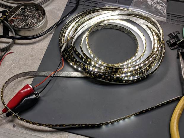
    The roll of warm-white LEDs I used for the first sewing machine lights has evidently aged out:

    Failed warm-white LED strip
    Failed warm-white LED strip

    They’ve been wrapped on their original roll, tucked in an antistatic bag, for the last five years, so it’s not as if they’ve been constantly abused.

    All the cool-white LEDs on an adjacent roll in the same bag still work perfectly, so you’re looking at inherent vice.

    I harvested the three longest functional sections and dumped the remainder in the electronics recycling box.

    COB LEDs provide much more light, if only because they run at higher power densities, and seem to be much better cost-performers:

    Juki TL-2010Q COB LED - installed - rear view
    Juki TL-2010Q COB LED – installed – rear view

    Admittedly, I haven’t looked at the RGB LED strips in a while, either.

  • MPCNC Drag Knife: LM12UU Linear Bearing

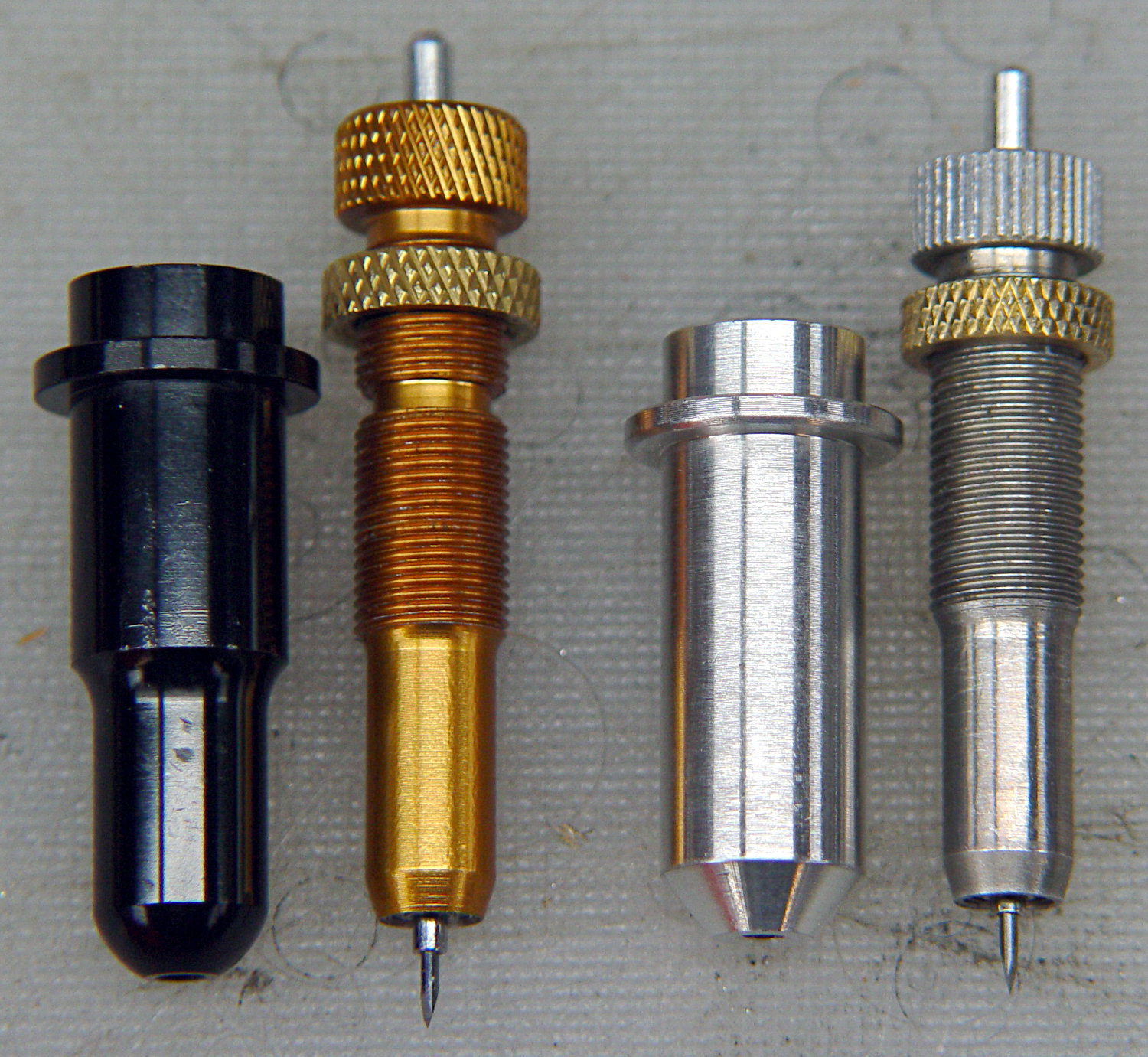
    The anodized body of the drag knife on the left measures exactly 12.0 mm OD:

    Drag Knife holders - detail
    Drag Knife holders – detail

    Which happy fact suggested I might be able to use a standard LM12UU linear bearing, despite the obvious stupidity of running an aluminum “shaft” in a steel-ball bearing race:

    Drag Knife - LM12UU holder - solid model
    Drag Knife – LM12UU holder – solid model

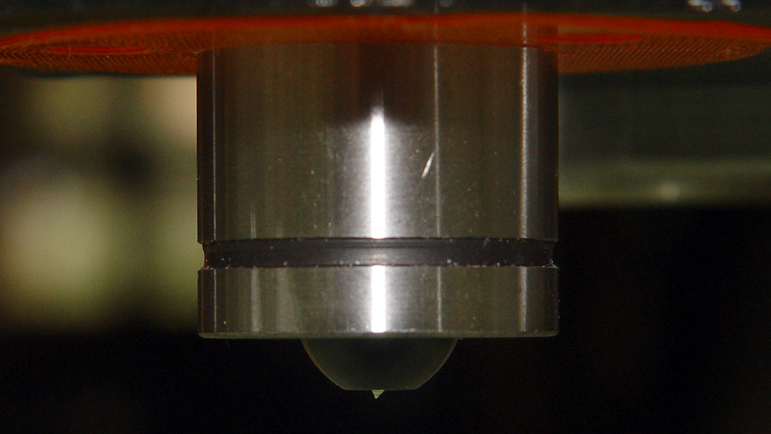
    The 12 mm section extends about halfway through the bearing, with barely 3 mm extending out the far end:

    Drag Knife - LM12UU - knife blade detail
    Drag Knife – LM12UU – knife blade detail

    Because the knife body isn’t touching the bearing for the lower half of its length, it’ll probably deflect too much in the XY plane, but it’s simple enough to try out.

    As before, the knife body’s flange is a snug fit in the hole bored in the upper disk:

    Drag Knife - spring plate test fit
    Drag Knife – spring plate test fit

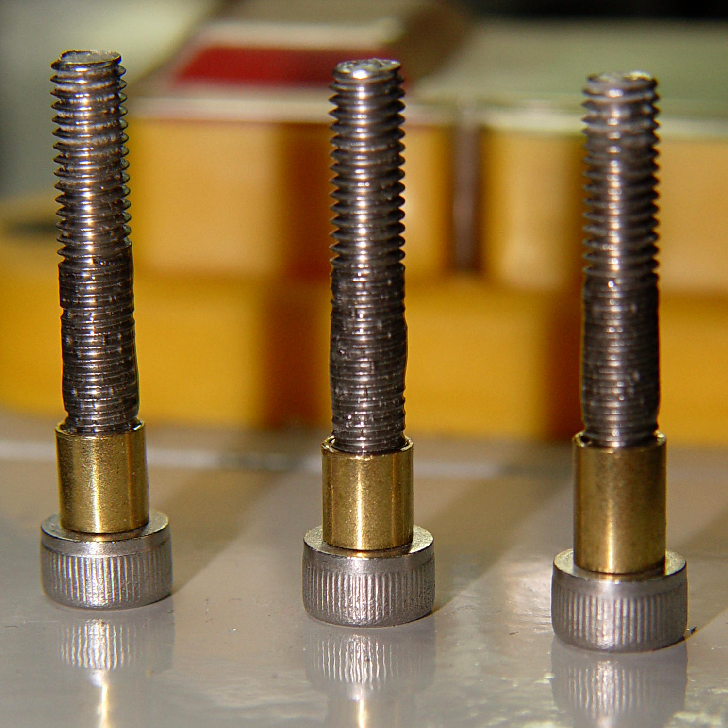
    This time, I tried faking stripper bolts by filling the threads of ordinary socket head cap screws with epoxy:

    Ersatz stripper bolts - epoxy fill
    Ersatz stripper bolts – epoxy fill

    Turning the filled section to match the thread OD showed this just wasn’t going to work at all, so I turned the gunked section of the threads down to about 3.5 mm and continued the mission:

    Drag Knife - LM12UU holder - assembled
    Drag Knife – LM12UU holder – assembled

    Next time, I’ll try mounting the disk on telescoping brass tubing nested around the screws. The motivation for the epoxy nonsense came from the discovery that real stainless steel stripper bolts run five bucks each, which means I’m just not stocking up on the things.

    It slide surprisingly well on the cut-down screws, though:

    Drag Knife - applique templates
    Drag Knife – applique templates

    Those appliqué templates came from patterns for a block in one of Mary’s current quilting projects, so perhaps I can be of some use whenever she next needs intricate cutouts.

    The OpenSCAD source code as a GitHub Gist:

    // Drag Knife Holder using LM12UU linear bearing
    // Ed Nisley KE4ZNU – 2019-04-26
    Layout = "Show"; // [Build, Show, Puck, Mount, Plate]
    /* [Extrusion] */
    ThreadThick = 0.25; // [0.20, 0.25]
    ThreadWidth = 0.40; // [0.40]
    /* [Hidden] */
    Protrusion = 0.1; // [0.01, 0.1]
    HoleWindage = 0.2;
    inch = 25.4;
    function IntegerMultiple(Size,Unit) = Unit * ceil(Size / Unit);
    ID = 0;
    OD = 1;
    LENGTH = 2;
    //- Adjust hole diameter to make the size come out right
    module PolyCyl(Dia,Height,ForceSides=0) { // based on nophead's polyholes
    Sides = (ForceSides != 0) ? ForceSides : (ceil(Dia) + 2);
    FixDia = Dia / cos(180/Sides);
    cylinder(r=(FixDia + HoleWindage)/2,h=Height,$fn=Sides);
    }
    //- Dimensions
    // Basic shape of DW660 snout fitting into the holder
    // Lip goes upward to lock into MPCNC mount
    Snout = [44.6,50.0,9.6]; // LENGTH = ID height
    Lip = 4.0; // height of lip at end of snout
    // Knife holder & suchlike
    KnifeBody = [12.0,15.9,2.0]; // flange epoxied to top of diamond shaft, with epoxy fillet
    WallThick = 4.0; // minimum thickness / width
    Screw = [4.0,8.5,8.0]; // holding it all together, OD = washer
    Insert = [4.0,6.0,10.0]; // brass insert
    Bearing = [12.0,21.0,30.0]; // linear bearing body
    Plate = [KnifeBody[ID],Snout[OD] – WallThick,KnifeBody[LENGTH] + WallThick]; // spring reaction plate
    PlateGuide = [4.0,4.8,Plate[LENGTH]]; // … guide tubes
    PuckOAL = max(Bearing[LENGTH],(Snout[LENGTH] + Lip)); // total height of DW660 fitting
    echo(str("PuckOAL: ",PuckOAL));
    Key = [Snout[ID],25.7,(Snout[LENGTH] + Lip)]; // rectangular key
    NumScrews = 3;
    ScrewBCD = 2.0*(Bearing[OD]/2 + Insert[OD]/2 + WallThick);
    NumSides = 9*4; // cylinder facets (multiple of 3 for lathe trimming)
    module DW660Puck() {
    translate([0,0,PuckOAL])
    rotate([180,0,0]) {
    cylinder(d=Snout[OD],h=Lip/2,$fn=NumSides);
    translate([0,0,Lip/2])
    cylinder(d1=Snout[OD],d2=Snout[ID],h=Lip/2,$fn=NumSides);
    cylinder(d=Snout[ID],h=PuckOAL,$fn=NumSides);
    intersection() {
    translate([0,0,0*Lip + Key.z/2])
    cube(Key,center=true);
    cylinder(d=Snout[OD],h=Lip + Key.z,$fn=NumSides);
    }
    }
    }
    module MountBase() {
    difference() {
    DW660Puck();
    translate([0,0,-Protrusion]) // bearing
    PolyCyl(Bearing[OD],2*PuckOAL,NumSides);
    for (i=[0:NumScrews – 1]) // clamp screws
    rotate(i*360/NumScrews)
    translate([ScrewBCD/2,0,-Protrusion])
    rotate(180/8)
    PolyCyl(Insert[OD],2*PuckOAL,8);
    }
    }
    module SpringPlate() {
    difference() {
    cylinder(d=Plate[OD],h=Plate[LENGTH],$fn=NumSides);
    translate([0,0,-Protrusion]) // knife holder body
    PolyCyl(KnifeBody[ID],2*PuckOAL,NumSides);
    translate([0,0,Plate[LENGTH] – KnifeBody[LENGTH]]) // flange, snug fit
    PolyCyl(KnifeBody[OD],KnifeBody[LENGTH] + Protrusion,NumSides);
    for (i=[0:NumScrews – 1]) // clamp screws
    rotate(i*360/NumScrews)
    translate([ScrewBCD/2,0,-Protrusion])
    rotate(180/8)
    PolyCyl(PlateGuide[OD],2*PuckOAL,8);
    }
    }
    //—–
    // Build it
    if (Layout == "Puck")
    DW660Puck();
    if (Layout == "Plate")
    SpringPlate();
    if (Layout == "Mount")
    MountBase();
    if (Layout == "Show") {
    MountBase();
    translate([0,0,1.6*PuckOAL])
    rotate([180,0,0])
    SpringPlate();
    }
    if (Layout == "Build") {
    translate([0,Snout[OD]/2,PuckOAL])
    rotate([180,0,0])
    MountBase();
    translate([0,-Snout[OD]/2,0])
    SpringPlate();
    }

  • Seam Ripper Cover

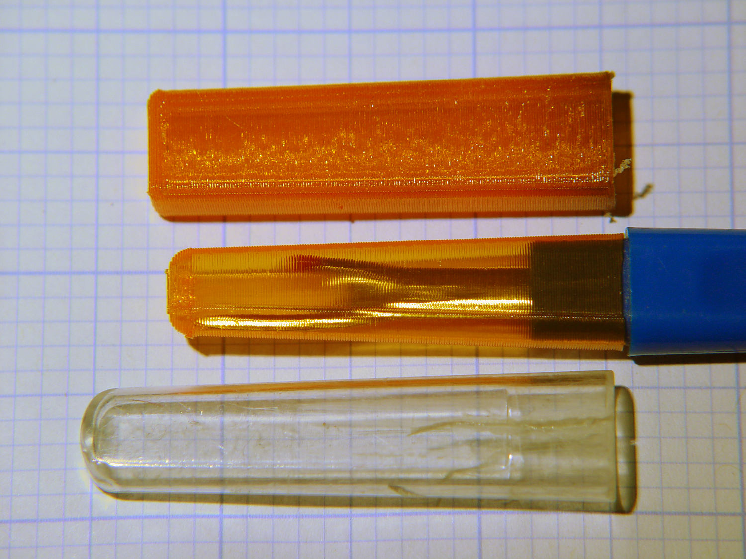
    The cover for Mary’s favorite seam ripper cracked long ago, has been repaired several times, and now needs a replacement:

    Seam Ripper cover - overview
    Seam Ripper cover – overview

    The first pass (at the top) matched the interior and exterior shapes, but was entirely too rigid. Unlike the Clover seam ripper, the handle has too much taper for a thick-walled piece of plastic.

    The flexy thinwall cover on the ripper comes from a model of the interior shape:

    Seam Ripper Cover - handle model
    Seam Ripper Cover – handle model

    It’s not conspicuously tapered, but OpenSCAD’s perspective view makes the taper hard to see. The wedge on top helps the slicer bridge the opening; it’s not perfect, just close enough to work.

    A similar model of the outer surface is one thread width wider on all sides, so subtracting the handle model from the interior produces a single-thread shell with a wedge-shaped interior invisible in this Slic3r preview:

    Seam Ripper Cover - exterior - Slic3r preview
    Seam Ripper Cover – exterior – Slic3r preview

    The brim around the bottom improves platform griptivity. The rounded top (because pretty) precludes building it upside-down, but if you could tolerate a square-ish top, that’s the way to go.

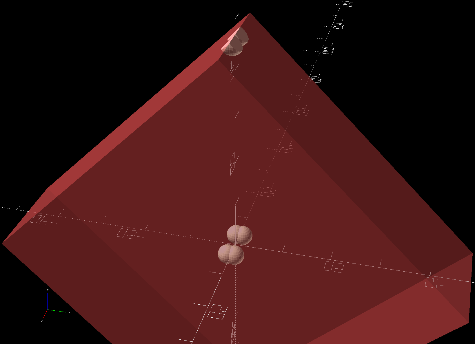
    Both models consist of hulls around eight strategically placed spheres, with the wedge on the top of the handle due to the intersection of the hull and a suitable cube. This view shows the situation without the hull:

    Seam Ripper Cover - handle model - cube intersection
    Seam Ripper Cover – handle model – cube intersection

    The spheres overlap, with the top set barely distinguishable, to produce the proper taper. I measured the handle and cover’s wall thicknesses, then guesstimated the cover’s interior dimensions from its outer size.

    The handle’s spheres have a radius matching its curvature. The cover’s spheres have a radius exactly one thread width larger, so the difference produces the one-thread-wide shell.

    Came out pretty nicely, if I do say so myself: the cover seats fully with an easy push-on fit and stays firmly in place. Best of all, should it get lost (despite the retina-burn orange PETG plastic), I can make another with nearly zero effort.

    The Basement Laboratory remains winter-cool, so I taped a paper shield over the platform as insulation from the fan cooling the PETG:

    Seam Ripper Cover - platform insulation
    Seam Ripper Cover – platform insulation

    The shield goes on after the nozzle finishes the first layer. The masking tape adhesive turned into loathesome goo and required acetone to get it off the platform; fortunately, the borosilicate glass didn’t mind.

    The OpenSCAD source code as a GitHub Gist:

    // Cover for old seam ripper
    // Ed Nisley – KE4ZNU
    // 2019-03
    /* [Layout Options] */
    Layout = "Build"; // [Show,Build]
    Part = "Handle"; // [Handle,CoverSolid,Cover]
    /* [Extrusion Parameters] */
    ThreadWidth = 0.40;
    ThreadThick = 0.25;
    HoleWindage = 0.2;
    Protrusion = 0.1;
    //—–
    // Dimensions
    /* [Dimensions] */
    WallThick = 1*ThreadWidth;
    CapInsideLength = 48.0;
    CornerRadius = 2.0; // handle at base
    Base = [11.0,5.5,0.0]; // handle at base
    Tip = [8.2,3.7,CapInsideLength]; // inferred at tip
    HandleOC = [Base – 2*[CornerRadius,CornerRadius,0.0],
    Tip – 2*[CornerRadius,CornerRadius,CornerRadius/2]
    ];
    NumSides = 2*3*4;
    //—–
    // Useful pieces
    // Handle is basically the interior of the cover
    module Handle() {
    intersection() {
    hull()
    for (i=[-1,1], j=[-1,1], k=[0,1])
    translate([i*HandleOC[k].x/2,j*HandleOC[k].y/2,k*HandleOC[k].z])
    sphere(r=CornerRadius,$fn=NumSides);
    translate([0,0,-CornerRadius/2]) // chop tip for better bridging
    rotate([45,0,0])
    cube([2*Base.x,CapInsideLength*sqrt(2),CapInsideLength*sqrt(2)],center=true);
    }
    }
    module CoverSolid() {
    hull()
    for (i=[-1,1], j=[-1,1], k=[0,1])
    translate([i*HandleOC[k].x/2,j*HandleOC[k].y/2,k*HandleOC[k].z])
    sphere(r=CornerRadius + WallThick,$fn=NumSides);
    }
    module Cover() {
    difference() {
    CoverSolid();
    Handle();
    translate([0,0,-CornerRadius])
    cube(2*Base + [0,0,2*CornerRadius],center=true);
    }
    }
    //—–
    // Build things
    if (Layout == "Build") {
    Cover();
    }
    if (Layout == "Show")
    if (Part == "Handle")
    Handle();
    else if (Part == "CoverSolid")
    CoverSolid();
    else if (Part == "Cover")
    Cover();

  • Kenmore 158: Goobered Screws

    One of Mary’s quilting group arrived with a machine in dire need of cleaning and oiling. These screws hold the throat plate in place:

    Kenmore screws - goobered
    Kenmore screws – goobered

    They’re standing in a pair of threaded brass inserts (found in the benchtop litter) to show off their tops.

    The left screw came out easily, although a few licks with a fine file eased the slot corners.

    The one on the right, however, was firmly jammed in place, with the crappy little Kenmore sewing machine screwdriver causing the goobering. I deployed my Brownell’s Gunsmith Screwdriver Bits, applied slightly less force than would ordinarily call for an overnight penetrating oil session, got the screw out, and cleaned it up:

    Kenmore screws - smoothed
    Kenmore screws – smoothed

    A dot of oil on the threads should keep it happy for the foreseeable future.