Just before midnight, the garage door opened, but, being early-to-bed folks, it wasn’t either of us. I pulled my fingernails out of the ceiling, padded out to the garage, verified there was nobody (not even a critter more substantial than a spider) inside, closed the door with the hardwired control button on the wall, and went back to bed. An hour later, the door opened again, then tried to take a bite out of me when I walked under it.
I pulled the opener’s plug, yanked its emergency release latch, lowered the door, and returned to bed; it was not a restful night.
The key to the diagnosis came from the little yellow LED on the back of the opener, just above the purple LEARN button:

In addition to indicating various programming states, it also lights when the opener’s radio receives a transmission from one of the remote controls. The LED was flickering continuously, showing that something was hosing the receiver with RF.
We have three remotes: one in the car, one on my bike, and one in the back room overlooking the garage. None of them worked reliably, suggesting the RF interference was clobbering their transmissions.
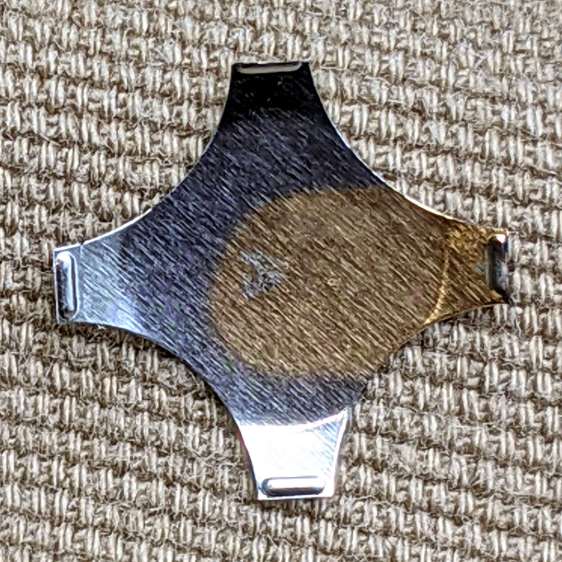
Disabling the remotes by removing their batteries (which were all good) also stopped the interference. Reinstalling the batteries one-by-one identified the rogue opener:

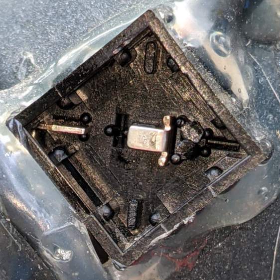
The slip of paper let me isolate the battery terminal and stick a milliammeter in the circuit, which showed the remote was drawing about 1.5 mA continuously. I thought one of the pushbutton switches had gone flaky, but swapping an unused one for the main door switch had no effect.
I lost track of which remote it was, but it lived in the car or the back room for all its life, so it hasn’t suffered extreme environmental stress. I have no idea why it would fail late one night, although I admit to not monitoring the LED on a regular basis. For whatever it’s worth, in the weeks leading up to the failure, activating the opener sometimes required two pokes at the remote, but nothing bad enough to prompt any further investigation.
A new cheap knockoff remote arrived in few days and it’s all good.
Protip: different openers, even from the same company, use different RF frequencies. For Craftsman openers, the color of the LEARN button is the key to the frequency; purple = 139.53753 MHz.