Ed Nisley's Blog: Shop notes, electronics, firmware, machinery, 3D printing, laser cuttery, and curiosities. Contents: 100% human thinking, 0% AI slop.
A gusty thunderstorm knocked out power across Dutchess County, including half the service to our house. Being glad the refrigerator and freezer were on the live phase, I shut off the affected breakers on the dead phase, as well as all the 240 V breakers, and, with the living room darkened, we skipped our evening storytime.
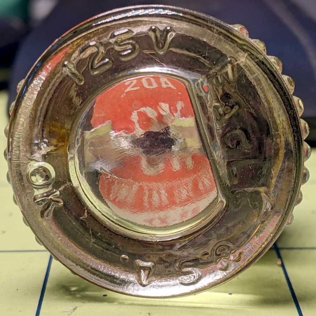
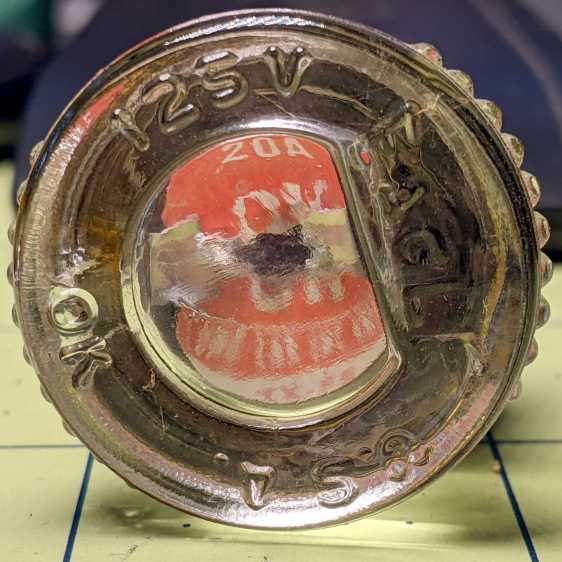
By the next morning, a quick lamp test showed the recloser out on the pole had worked its magic, so I flipped all the breakers back on. The living room remained dark, prompting an investigation of the fuse box feeding the original house wiring:
Given what happens while wind and falling branches knock power lines askew, anything is possible. I have no idea where the fault current went, but replacing the fuse brought the living room back to normal.
None of the various UPS / lamps / phones seem damaged; I admit not peering inside the outlets to check for arc damage.
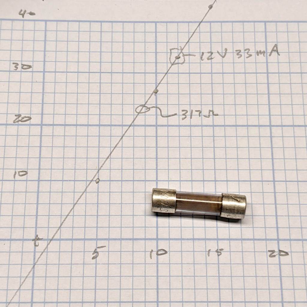
The slope suggests a 330 Ω resistor, but the internal PCB sports a pair of 150 Ω SMD resistors.
I don’t believe the X-axis intercept for a moment, but 1.5 V seems about right for an amber LED.
Oh, and the DMM fuse doesn’t have a ceramic body. You’re seeing the vaporized remains of a 315 mA fuse neatly deposited over the inside of the glass tube after being shorted across a 3 A bench supply.
I hate it when that happens. Replacing it emptied the little bag of those meter fuses; next time it’ll get a half amp fuse.
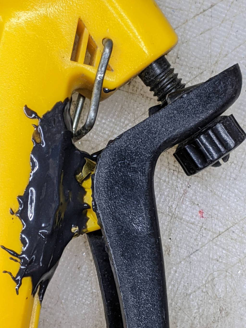
A winning entry in the “The Bigger the Blob, the Better the Job” category:
Garden Sprayer – pivot repair
Buried under the epoxy is the flimsy tab with the pivot around which the handle moves. Any sideways force will did snap the tab off flush with the body. I had previously repaired it with solvent adhesive, so something more substantial seemed appropriate.
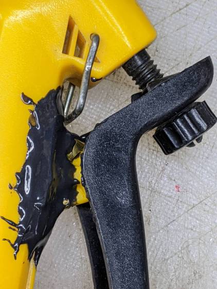
A closer look shows the edges of the brass flange I formed around the tab to absorb the stress:
Garden Sprayer – pivot repair – detail
It’s pretty much fully depreciated, but if I don’t use the epoxy it will go bad on the shelf, so …
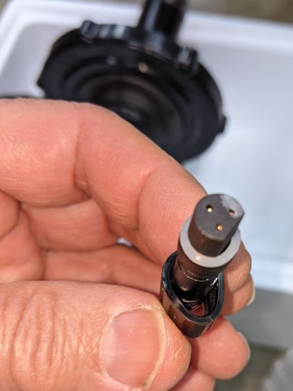
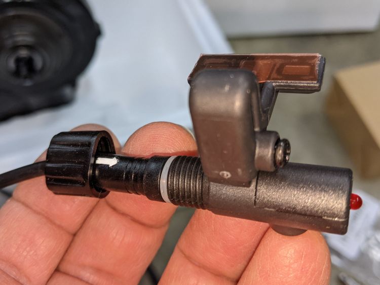
A Bafang BBS02 (for a friend’s upright bike) arrived with a deformed speed sensor nut:
Bafang BBS02 – Deformed speed sensor nut – end view
It traveled halfway around the planet while trapped underneath the motor and, if it rode in the top layer or two of containers, the combination of pressure and heat would be irresistible.
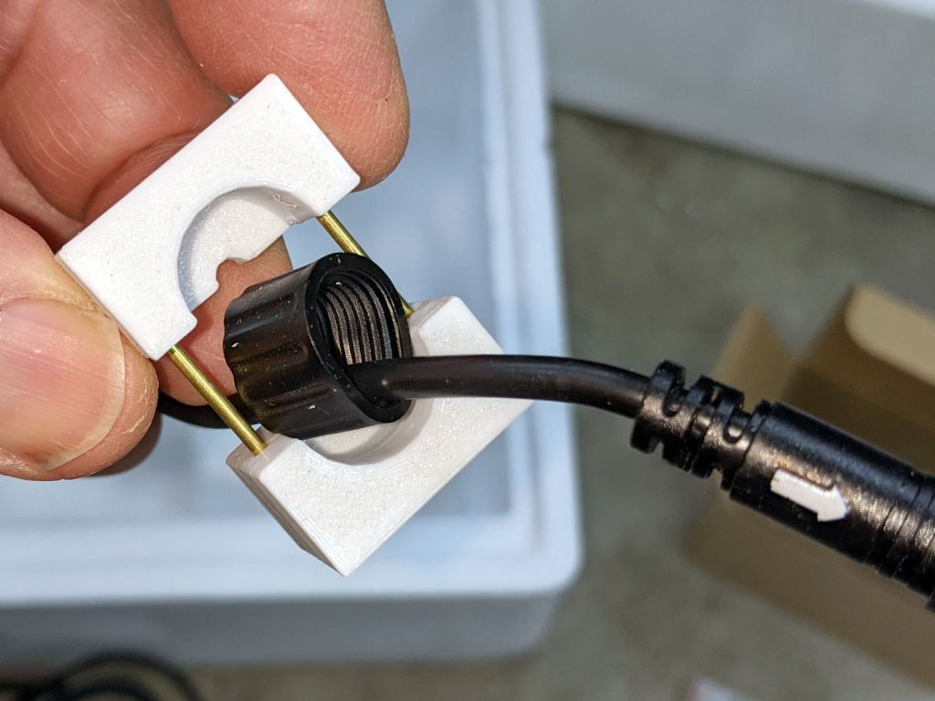
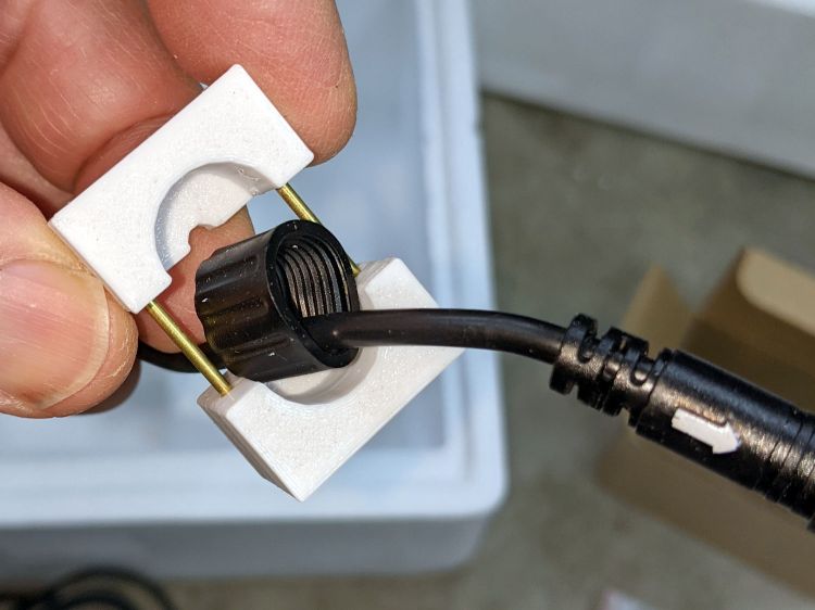
The plastic was stiff and I couldn’t force the nut over the connector using as much force as seemed reasonable:
Bafang BBS02 – Deformed speed sensor nut – test assembly
On the upside, the nut just compresses the silicone washer between the connector and the sensor to make a waterproof joint, so it need not have perfect threads or a uniform shape. Once the nut is in place, it will likely never be removed and should never bother anyone else.
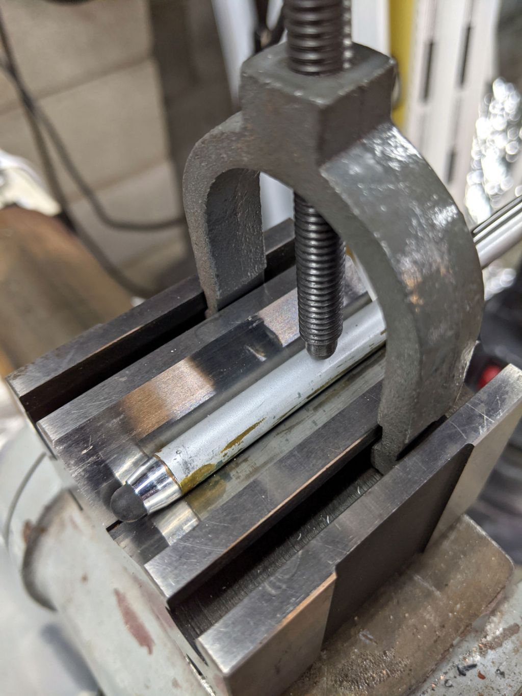
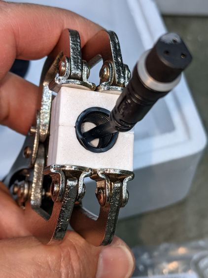
Being unwilling to apply a hot-air gun near the cable, I decided to try slowly cold-forming the nut inside a mold:
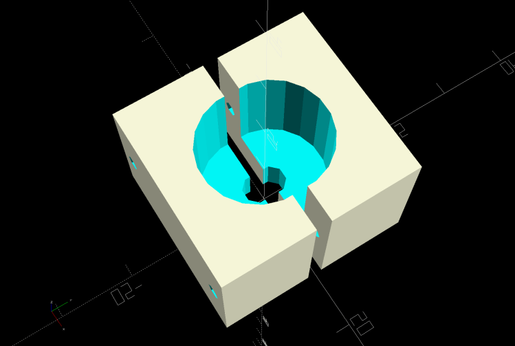
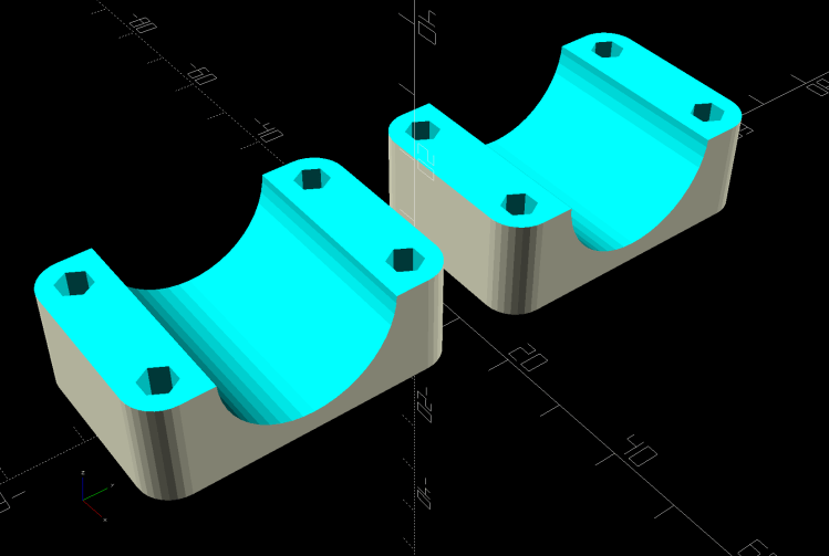
Sensor Nut mold – solid model
The gap isn’t a kerf: the two halves meet to form a cylindrical pocket. The smaller holes fit a pair of brass tubes keeping the halves lined up while I arrange things:
A few days of squashing made it round-er, whereupon I applied the clamp directly against the remaining high point with the other side cradled in the mold. It still doesn’t slide over the connector body, but I’m not in a rush.
Bafang tech support generously sent a speed sensor extension cable from which I can extract a good nut, which will require cutting and splicing the cable from the motor.
This is laid in against a need I hope never occurs:
Dripworks 0.75 inch pipe clamp
It’s intended to clamp around one of the Dripworks mainline pipes carrying water from the pressure regulator to the driplines in the raised beds, should an errant shovel or fork find the pipe.
It descends from a long line of soaker hoseclamps, with a 25 mm ID allowing for a silicone tape wrap as a water barrier.
This file contains hidden or bidirectional Unicode text that may be interpreted or compiled differently than what appears below. To review, open the file in an editor that reveals hidden Unicode characters.
Learn more about bidirectional Unicode characters
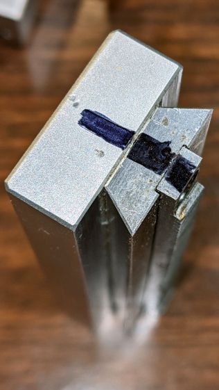
Protip: before dismantling a fitted slide, mark one end so you know how to put it back together. Bonus points for taking a picture:
Microscope Stage Positioner – slide marking
Double bonus points for writing a blog post.
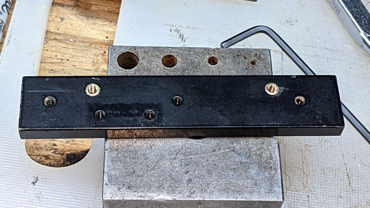
Rather than fight with the existing fine-pitch USA-ian screws, I drilled out their threaded holes:
Microscope Stage Positioner – Y slide drilling
And epoxied 3 mm brass inserts in their place:
Microscope Stage Positioner – Y slide M3 inserts
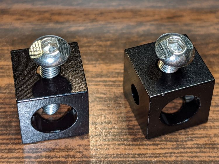
Those holes match up with a pair of corner cubes normally appearing on the end of the beams:
Microscope Stage Positioner – BHCS mods for Makerbeam
It turns out M3 button head cap screws will slide into the beams if you file the slightest angle on opposite sides of the button, although a small bag of tiny tee nuts should arrive in a while.
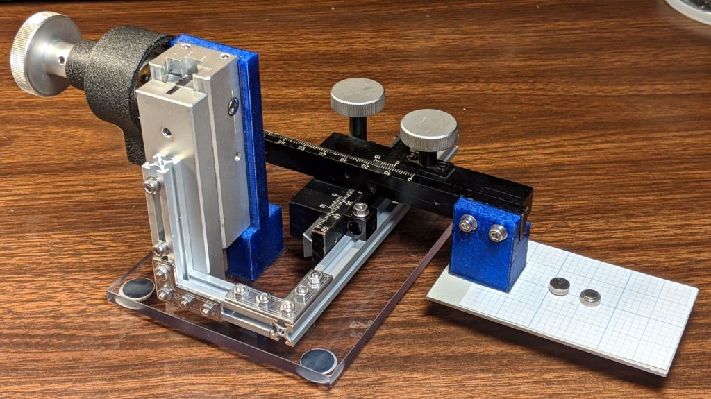
Then a variety of brackets spliced everything together:
Microscope Stage Positioner – Makerbeam detail
Although it looks strictly from industrial, it actually wasn’t much better than the plastic edition and, in fact, the beam supporting the XY slides sagged about the same 5 mm. The plastic upright post also contributed a bit of wobble.
It turns out that the extruded aluminum beams have plenty of longitudinal and torsional stiffness, but all those flat steel fittings don’t.
There’s a way to work with the beam strengths, rather than against them, but that’s a story for another day …