Replacing the battery in an old Craftsman (!) multimeter brought its 10 A current-sense resistor into the light:
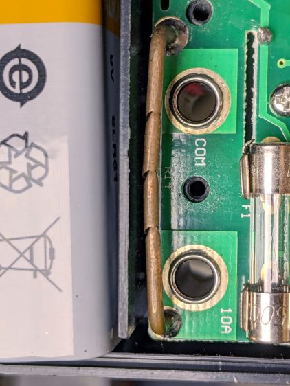
Unlike the contemporary AN8008/9 meters, it looks like an ordinary copper wire trimmed to the proper resistance by nipping it with a cutter.
It measures something under 10 mΩ, so I’m sure they adjusted the resistance by applying a known current and watching the meter reading while crunching the wire until the proper value appears.
I may have actually used the 10 A range, but I’d be hard pressed to say when or why, so the resistor is at least as good as it needs to be!

Comments
10 responses to “Multimeter Current-sense Resistor”
Hadn’t seen that particular type of shunt calibration before but certainly nothing wrong with it. The higher dollar shunts are likely laser trimmer but who knows. Last time I opened my flukes I don’t recall seeing the shunt trimmed this way but you can be sure I’ll look closer next time now.
I don’t recall seeing any evidence of trimming on the solar system shunts, but with 100A devices, 5% is probably close enough.
It looks crude, but it’s really the same thing as a laser trim: reduced cross-section = increased resistance.
Bonus: the front of the meter conspicuously says “10 A for 15 sec MAX every 15 min UNFUSED” so you know what you’re getting into.
Absolutely, and it does not require expensive equipment. It just reduces things done to manual calibration and human error. Just fine for lower volume and acceptance of risk in manufacturing. Kind of fun to think about actually by being able to make your own calibrated shunts.
I just checked the back of the meter and it has both a UL sticker and a Made in China label. It’s decades old, back when Sears could afford to have folks squeezing pliers at the end of the production line, even at their volumes. A different world!
Decades ago one morning in the 1960s my dad asked me if i’d like to “help” fix his car… he said he needed an ammeter to see if the generator(!) in the Willys Overland 4×4 Station Wagon was charging. His quick-and-dirty hack was a zero-center 50ua microammeter, two sewing pins, a pair of pliers and two alligator clip leads.
He turned on the headlights, let them get hot, then quickly pulled the plug off the back of one, and measured the resistance with a Simpson 260 roll-top meter (I wish I still had that). 6v and the hot ohms gave him the current for one headlight… if I remember correctly about 10 amps…
The microammeter and clip leads were conected to the sewing pins, and using needlenose pliers the pins inserted through the battery ground cable and moved apart until the one still-connected headlight’s current read on the microammeter as 15ua… swapping the leads showed -15ua… which he said was was correct for the ignition load and the headlight load on the battery… switching off the headlights dropped the current to a couple of amps or so (the ignition)… connecting the generator showed some more due the current in the field winding… reving the engine showed no change… Hmmm looks like we have a dead generator… A couple of wrenches to remove the old one, fiddling with the brushes showed that the were gone, and the commutator was pitted.. a trip to the auto parts store in the other car resulted in a rebuilt genny. We installed that, now shows a normal charge.
His was an interesting hands-on way to explain voltage, cold-versus-hot resistance, current shunts, resistor taps, and more to a 9 or 10 year old…
Later on I discovered the ammeter in the dash… apparently he already knew the genny was dead, all of that trickery with the pins and microammeter was all just a teach session… that was how my dad did things…
A tip o’ the bike helmet to a great teacher!
That’s awesome. I think my Dad did something similar when we built a Heathkit 2M radio. First power up, no audio. Turns out the power pin on the audio amp wasn’t soldered. I bet he did that to create an easy to find problem.
I wonder if they used a non-conductive cutter while monitoring the impedance. Ceramic would do the trick.
A steel cutter jaw looks pretty much like an insulator in a copper conductor: something like an order of magnitude lower conductivity.
But, if I were on the line, I’d want a nonconducting blade, too! [grin]