Ed Nisley's Blog: Shop notes, electronics, firmware, machinery, 3D printing, laser cuttery, and curiosities. Contents: 100% human thinking, 0% AI slop.
The tab supporting the strut with the center slides for the lower drawers in our Whirlpool refrigerator broke of its own accord. This is a problem of long standing, somewhat exacerbated by the fact that lifting the strut will break the tab without much effort at all, but this time the drawers pulled the strut downward hard enough to not only break the tab, but also tear the small tabs that align the bracket right out of the frame.
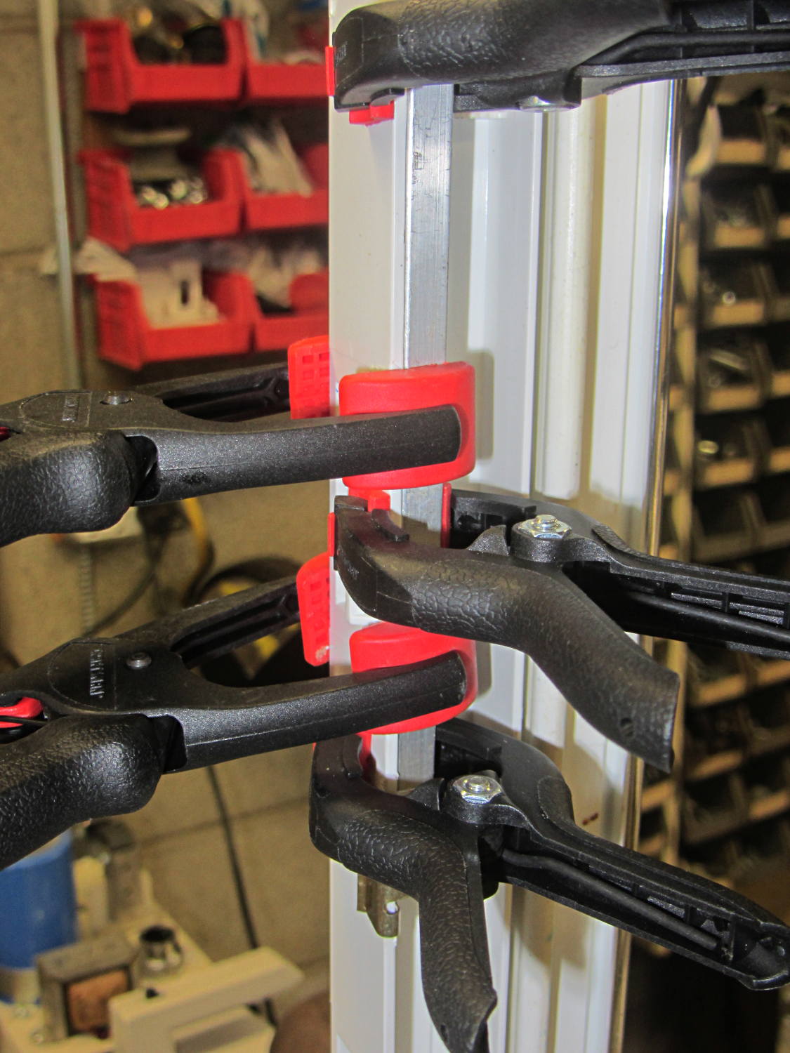
While pondering the problem, I glued the broken chunk back into the frame:
Refrigerator Drawer Strut – clamping front plate
We agreed that, after nigh onto two decades, it would be OK to swap the position of the two drawers, so as to let the strut use the undamaged part of the frame seen below. Presumably, we’ll eventually get used to having the apples on the right and the veggies on the left.
But it was obvious Something Serious Had To Be Done about the tab.
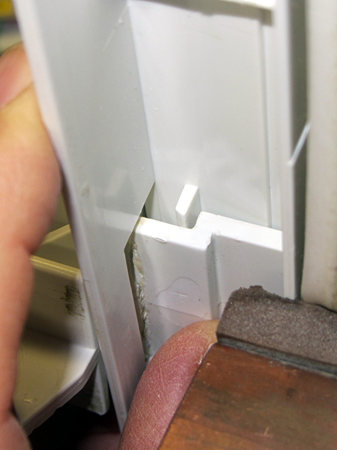
The tab should align like this inside the frame:
Refrigerator Drawer Strut Tab – alignment
The rightmost part of the tab rests atop a U-shaped metal bar that also supports and stiffens the entire front of the frame, but cantilevering the weight of both drawers on that extended tab overpowered my last attempt at making a glue joint. Soooo, I decided to build a (wait for it …) 3D printed part that screws firmly to the front of the strut.
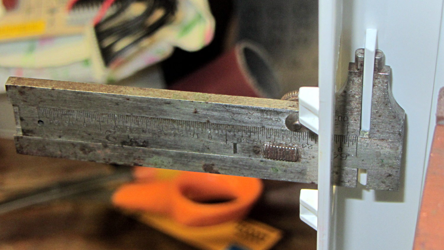
The first step involved introducing the strut to Mr Belt Sander to strip the wreckage of the OEM tab from the front end (visible through the opening) and smooth things out, then measuring the remainder. The locating flange inside the frame almost defeated me, but eventually I found a tool that fit inside the strut opening and around the flange:
Refrigerator Drawer – measuring flange
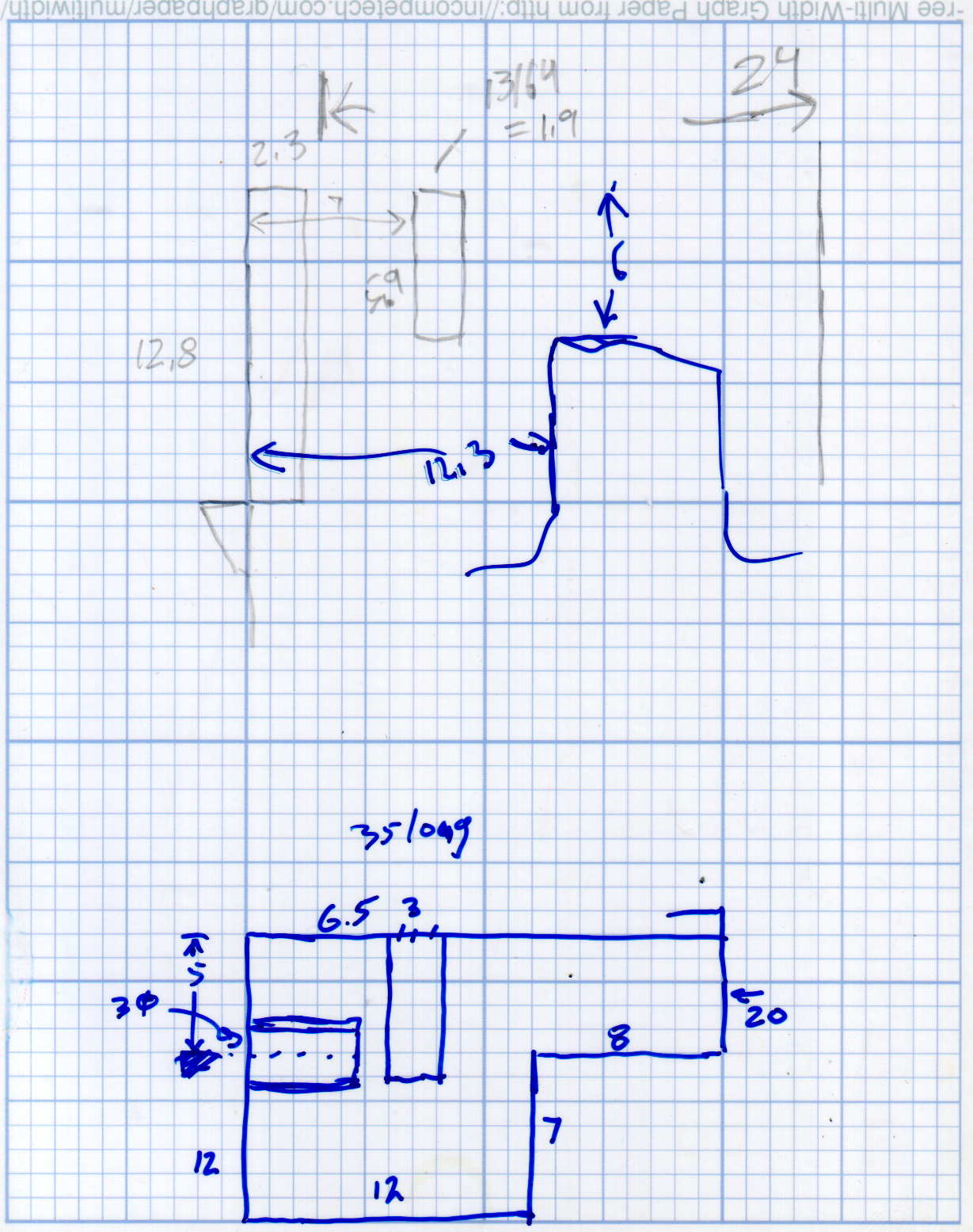
Which produced a sketch of the key dimensions:
Refrigerator Drawer Strut – Dimension Doodles
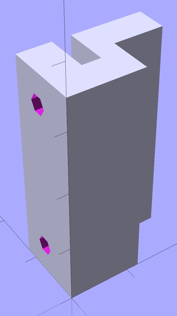
Which became an extruded polygon with a few holes punched in the side:
Refrigerator Shelf Strut Tab – solid model
Building it standing up wraps the plastic threads around the entire tab and stacks the layers along the length of the tab. Doing it lying down in the obvious hump-up orientation would put the layers parallel to the bottom surface, where they can pull apart under load.
The key innovation here involves being willing to assemble the tab to the strut in situ, without insisting it fit through the frame opening and be more-or-less easily removable. That let me bulk up the tab to match the end of the strut, fill the entire frame opening with plastic, and get enough bulk for a pair of 4-40 screws that, being loaded in shear, should withstand the weight of all those fruits & veggies in the drawers.
The screws simply thread into the holes in the tab, without benefit of tapping. The OpenSCAD code now includes a pair of nut traps, but I’m hoping they won’t be needed.
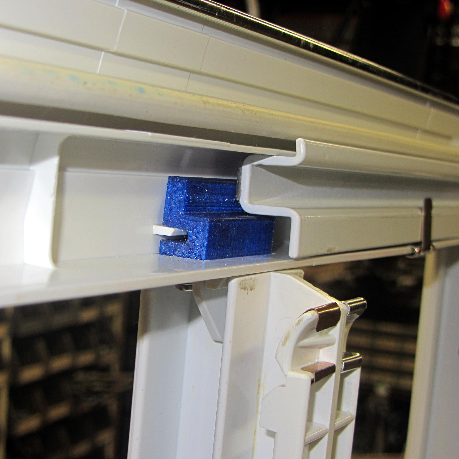
The new tab really does fill the space available:
Refrigerator Drawer Strut – new tab in place
The OpenSCAD code now moves the notch half a millimeter further away from the strut to center it over the ridge. What’s not obvious is how the frame slants toward the tab over the U-bar: the tab just barely clears and probably should have a tapered nose. You may add that if you like.
The U-shaped bar constrains the tab pretty firmly and supports the end, which should now be plump enough to withstand the forces involved. The screws sit horizontally with the frame installed and can’t pull out, which is why I think they can get along without nut traps.
It’s built in cyan PETG with three perimeter threads and 40% 3D Honeycomb fill, making it essentially a solid block of plastic; it’ll be interesting to see what fails next.
The OpenSCAD source code, which I hammered out in a white-hot fury:
// Refrigerator Shelf Strut Tab
// Ed Nisley KE4ZNU December 2015

//- Extrusion parameters must match reality!

ThreadThick = 0.25;
ThreadWidth = 0.40;

HoleWindage = 0.2;

Protrusion = 0.1;			// make holes end cleanly

inch = 25.4;

function IntegerMultiple(Size,Unit) = Unit * ceil(Size / Unit);

//----------------------
// Dimensions

TabSize = [20.0,12.0,35.0];							// length from bracket, height, width along front

SlotSize = [3.0,7.0];
SlotX = 7.0;

TabProfile = [
	[0,0],
	[12,0],	[12,7.0],
	[TabSize[0],7.0], [TabSize[0],TabSize[1]],
	[SlotX + SlotSize[0]/2,TabSize[1]],
	[SlotX + SlotSize[0]/2,5.0], [SlotX - SlotSize[0]/2,5.0],
	[SlotX - SlotSize[0]/2,TabSize[1]],
	[0,TabSize[1]]
];

ScrewY = 7.0;
ScrewOC = 25.0;
ScrewOD = 2.5;

NutOD = 6.6;					// across flats
NutThick = 2.5;

//----------------------
// Useful routines

module PolyCyl(Dia,Height,ForceSides=0) {			// based on nophead's polyholes

  Sides = (ForceSides != 0) ? ForceSides : (ceil(Dia) + 2);

  FixDia = Dia / cos(180/Sides);

  cylinder(r=(FixDia + HoleWindage)/2,
		h=Height,
	$fn=Sides);
}

//----------------------
// Build it

difference() {
	linear_extrude(height=TabSize[2],convexity=4)
		polygon(points=TabProfile);

	for (i=[-1,1]) {
		translate([-Protrusion,ScrewY,i*ScrewOC/2 + TabSize[2]/2])
			rotate([0,90,0])
				rotate(180/6)
					PolyCyl(ScrewOD,SlotX,6);
		translate([SlotX - SlotSize[0]/2 - NutThick - Protrusion,ScrewY,i*ScrewOC/2 + TabSize[2]/2])
			rotate([0,90,0])
				rotate(180/6)
					PolyCyl(NutOD,NutThick + SlotSize[0],6);
	}
}
Maybe that’ll last until we finally scrap out the refrigerator…
Mary started doing “ruler quilting” that involves sewing seams aligned with templates, only to find that the thumbscrew holding the (modified) presser foot obscures the view to the left of the needle:
Kenmore Model 158 – OEM Presser Foot Screw
The screw looked to be 6-32 and I wanted to use a socket head cap screw, but thread turns out to be 6-40. Having previously bought the Brownell’s Fillister Head Screw Assortment specifically to solve that problem, all I had to do was cut the screw to length:
Kenmore Model 158 – Small Presser Foot Screw
The washer epoxied to the screw provides a bit more bearing surface.
Rather than putz with a screwdriver, this handle locates itself around the screw head; turn until the blade clicks into the screw slot, then tighten or loosen as needed:
Kenmore Model 158 – Presser Foot – Driver and Screw
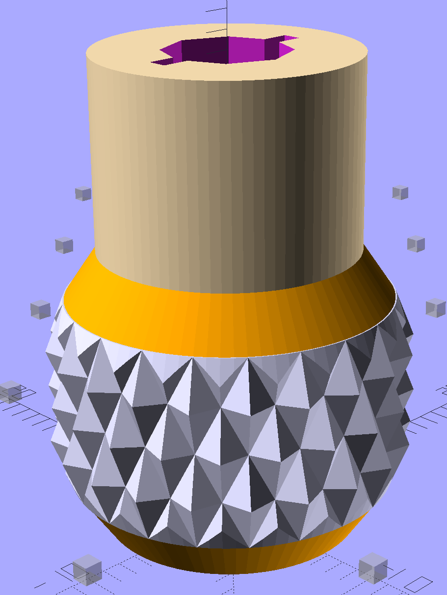
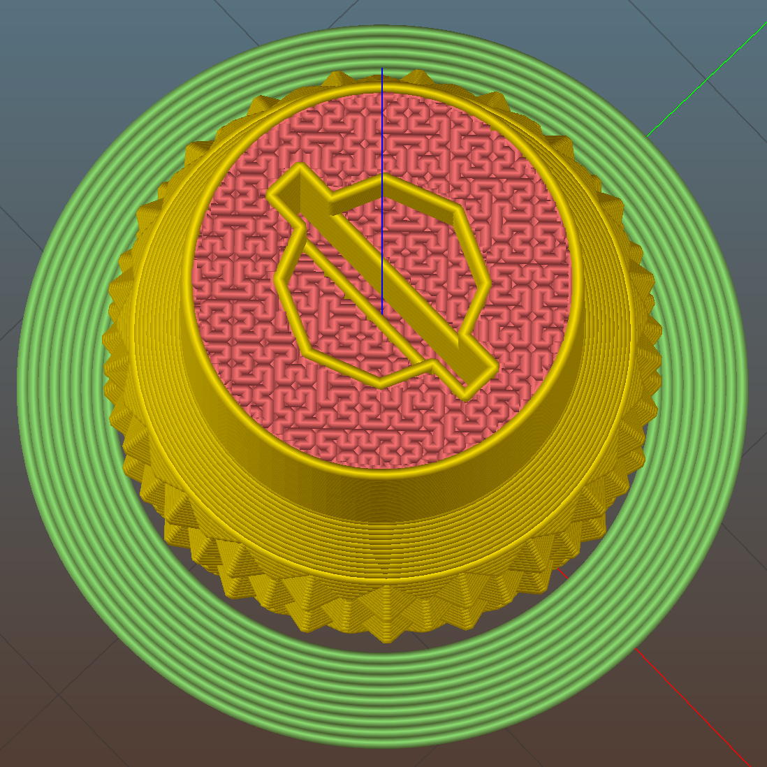
The slot holds a chunk of spring steel (barely visible in the driver’s snout in group photo above) that accounts for the fat shaft around the screw head:
Presser Foot Screw Driver – top – Slic3r
I think the shaft could be a few millimeters narrower, but a bit of meat around the ends of the blade will support it against the torque.
The screw head slot is about 1 mm and the blade is 0.75 mm. I chopped the blade to fit by whacking the spring with a poorly tempered cold chisel, then flexing across the impact line until it broke. That chisel needed sharpening anyhow.
A dab of epoxy along the slot edges holds the blade in place. I inserted it flush with the top of the socket, then lined up the screw and pushed, with the steel bottomed out in the screw head and riding down for a perfect fit.
Then it’s all good!
The OpenSCAD source code:
// Presser Foot Screw Driver for Kenmore Model 158
// Ed Nisley - KE4ZNU - December 2015

use <knurledFinishLib_v2.scad>

//- Extrusion parameters must match reality!
//  Print with 2 shells and 3 solid layers

ThreadThick = 0.20;
ThreadWidth = 0.40;

HoleWindage = 0.3;			// extra clearance to improve hex socket fit

Protrusion = 0.1;			// make holes end cleanly

inch = 25.4;

//----------------------
// Dimensions

SocketDia = 5.75;				// generous fit on 6-40 fillister screw head
SocketDepth = 3.2;

Blade = [9.0,1.0,ceil(SocketDepth + 5)];		// inserted metal driver blade
echo(str("Blade: ",Blade));

ShaftDia = 1.5*Blade[0];		// un-knurled section diameter
ShaftLength = 10.0;				//  ... length

KnurlLen = 10.0;				// length of knurled section
KnurlDia = 18.0;				//   ... diameter at midline of knurl diamonds
KnurlDPNom = 30;				// Nominal diametral pitch = (# diamonds) / (OD inches)

DiamondDepth = 1.0;				//   ... depth of diamonds
DiamondAspect = 2;				// length to width ratio

KnurlID = KnurlDia - DiamondDepth;		// dia at bottom of knurl

NumDiamonds = ceil(KnurlDPNom * KnurlID / inch);
echo(str("Num diamonds: ",NumDiamonds));

NumSides = 4*NumDiamonds;		// 4 facets per diamond

KnurlDP = NumDiamonds / (KnurlID / inch);				// actual DP
echo(str("DP Nom: ",KnurlDPNom," actual: ",KnurlDP));

DiamondWidth = (KnurlID * PI) / NumDiamonds;

DiamondLenNom = DiamondAspect * DiamondWidth;					// nominal diamond length
DiamondLength = KnurlLen / round(KnurlLen/DiamondLenNom);		//  ... actual

TaperLength = 0.50*DiamondLength;

KnobOAL = 2*TaperLength + KnurlLen + ShaftLength;

//----------------------
// Useful routines

module PolyCyl(Dia,Height,ForceSides=0) {			// based on nophead's polyholes

  Sides = (ForceSides != 0) ? ForceSides : (ceil(Dia) + 2);

  FixDia = Dia / cos(180/Sides);

  cylinder(r=(FixDia + HoleWindage)/2,
           h=Height,
	   $fn=Sides);
}

module ShowPegGrid(Space = 10.0,Size = 1.0) {

  Range = floor(50 / Space);

	for (x=[-Range:Range])
	  for (y=[-Range:Range])
		translate([x*Space,y*Space,Size/2])
		  %cube(Size,center=true);
}


//- Build it

ShowPegGrid();

difference() {
	union() {
		render(convexity=10)
		translate([0,0,TaperLength])			// knurled cylinder
			knurl(k_cyl_hg=KnurlLen,
				  k_cyl_od=KnurlDia,
				  knurl_wd=DiamondWidth,
				  knurl_hg=DiamondLength,
				  knurl_dp=DiamondDepth,
				  e_smooth=DiamondLength/2);
		color("Orange")							// lower tapered cap
		cylinder(r1=ShaftDia/2,
					r2=(KnurlDia - DiamondDepth)/2,
					h=(TaperLength + Protrusion),
					$fn=NumSides);
		color("Orange")							// upper tapered cap
		translate([0,0,(TaperLength + KnurlLen - Protrusion)])
			cylinder(r2=ShaftDia/2,
					r1=(KnurlDia - DiamondDepth)/2,
					h=(TaperLength + Protrusion),
					$fn=NumSides);
		color("Moccasin")						// cylindrical extension
		translate([0,0,(2*TaperLength + KnurlLen - Protrusion)])
			cylinder(r=ShaftDia/2,h=(ShaftLength + Protrusion),$fn=NumSides);

	}

	translate([0,0,(KnobOAL - SocketDepth + Protrusion)])
		PolyCyl(SocketDia,(SocketDepth + Protrusion),8);	// screw head socket

	translate([0,0,KnobOAL - (Blade[2] - Protrusion)/2])
		cube(Blade + [0,0,Protrusion],center=true);
}
An improved version of the 3D printed plastic bits going into the Hard Drive Platter Mood Light:
Hard Drive Mood Light – improved – solid model – Show view
The central pillar now has cutouts behind the Neopixel strips so you (well, I) can solder directly to the larger half-pads on the back, plus a boss on the top for better wire management:
Hard Drive Mood Light – improved – Pillar – solid model
I’m not entirely satisfied with the little slots for the strip edges; the resolution limits of 3D printing call for larger openings, but there’s not much meat around those pins up the edge.
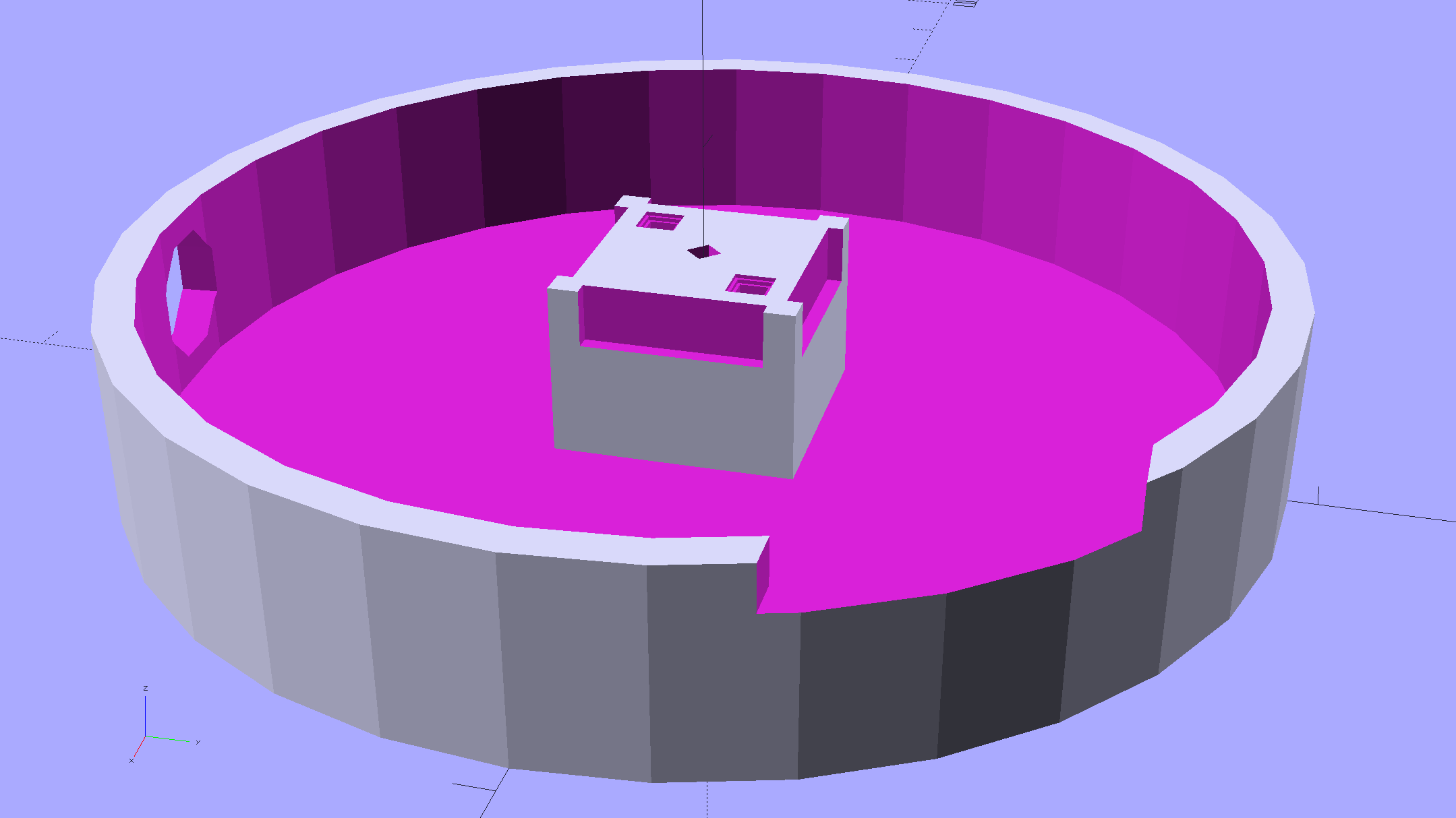
The base becomes much larger to hold the Arduino Pro Mini and gains an optional slot to let the programming cable reach the outside:
Hard Drive Mood Light – improved – Base – solid model
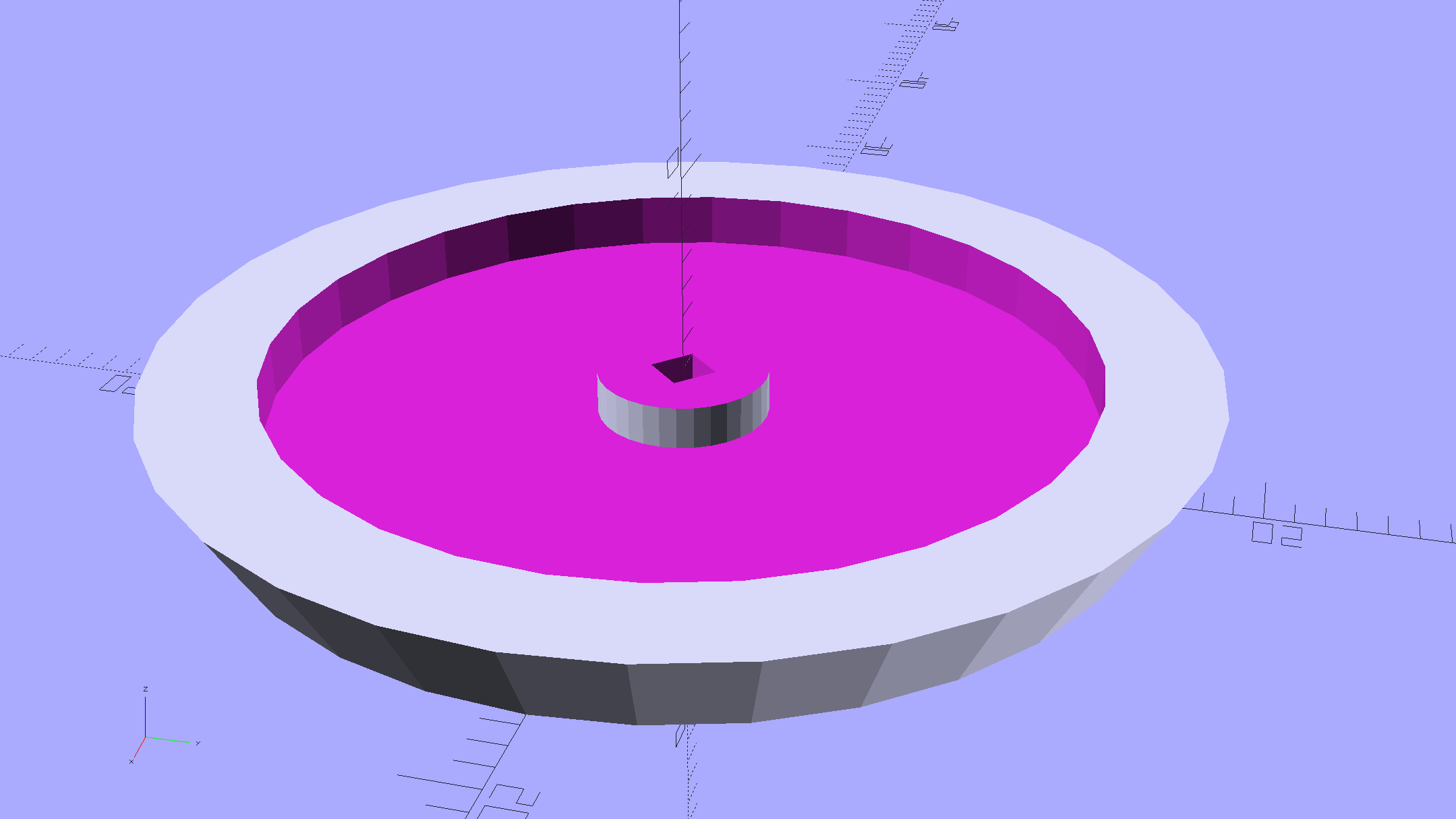
The cap has a boss matching the one atop the pillar:
Hard Drive Mood Light – improved – Cap – solid model
Both the cap & base have center features recessed by two thread thicknesses to let their rims apply a slight clamping force on the platters.
Our Larval Engineer says it really needs an internal battery with maybe four hours of runtime, a charging base station (ideally with inductive power transfer), buttons (or, better, a tilt switch / accelerometer) for mode selection, and perhaps a microphone to synchronize lighting effects with music. To my horror, her co-op job seems to have exposed her to Marketeers…
We do, however, agree that the Cap would look better in lathe-turned brass with a non-tarnish clearcoat.
The OpenSCAD source code:
// Hard Drive Platter Mood Light
// Ed Nisley KE4ZNU November 2015

Layout = "Spacers";					// Build Show Pixel LEDString Platters Pillar Spacers TopCap Base

CablePort = true;

ShowDisks = 2;						// number of disks in Show layout

//- Extrusion parameters must match reality!

ThreadThick = 0.25;
ThreadWidth = 0.40;

HoleWindage = 0.2;

Protrusion = 0.1;			// make holes end cleanly

inch = 25.4;

function IntegerMultiple(Size,Unit) = Unit * ceil(Size / Unit);

//----------------------
// Dimensions

ID = 0;
OD = 1;
LENGTH = 2;

Platter = [25.0,95.0,1.27];						// hard drive platters - must match actual thickness!

LEDStringCount = 3;								// number of LEDs on each strip
LEDStripCount = 4;								// number of strips (verify locating pin holes & suchlike)

WireSpace = 1.0;								// allowance for wiring along strip ends

Pixel = [13.0, 1000 / 144, 0.6];				// smallest indivisible unit of LED strip
PixelMargin = [1.0, 1.0, 2.0];					// LED and circuitry atop the strip

BeamAngle = 120;								// LED viewing angle
BeamShape = [
	[0,0],
	[Platter[OD]*cos(BeamAngle/2),-Platter[OD]*sin(BeamAngle/2)],
	[Platter[OD]*cos(BeamAngle/2), Platter[OD]*sin(BeamAngle/2)]
];

PillarSides = 12*4;

PillarCore = Platter[ID] - 2*(Pixel[2] + PixelMargin[2] + 2.0);		// LED channel distance across pillar centerline
PillarLength = LEDStringCount*Pixel[1] + Platter[LENGTH];
echo(str("Pillar core size: ",PillarCore));
echo(str("      ... length:"),PillarLength);

PCB = [34.5,17.5,1.6];								// Arduino Pro Mini (or whatever) PCB size
PCBClearTop = 5.0;
PCBClearBot = 5.0;
PCBHeight = PCB[2] + PCBClearBot + PCBClearTop;

PCBRadius = sqrt(pow(Platter[ID]/2 + PCB[1],2) + pow(PCB[0]/2,2));
echo(str("PCB Corner radius: ",PCBRadius));

CoaxConn = [7.8,11.2,5.0];							// power connector

Cap = [Platter[ID] + 4.0,Platter[ID] + 4.0 + 10*2*ThreadWidth,2*WireSpace + 6*ThreadThick];		// cap over top of pillar
CapSides = 8*4;

BaseClearHeight = max(PCBHeight,CoaxConn[OD]);

Base = [2.0 + 2*PCBRadius,2.0 + 2*PCBRadius + CoaxConn[LENGTH],BaseClearHeight + 6*ThreadThick];
BaseSides = 8*4;

Screw = [1.5,2.0,20.0];							// screws used to secure cap & pillar

Spacer = [Platter[ID],(Platter[ID] + 2*8),(Pixel[1] - Platter[LENGTH])];
echo(str("Spacer  OD: ",Spacer[OD]));
echo(str(" ... thick:",Spacer[LENGTH]));

LEDStripProfile = [
	[0,0],
	[Pixel[0]/2,0],
	[Pixel[0]/2,Pixel[2]],
	[(Pixel[0]/2 - PixelMargin[0]),Pixel[2]],
	[(Pixel[0]/2 - PixelMargin[0]),(Pixel[2] + PixelMargin[2])],
	[-(Pixel[0]/2 - PixelMargin[0]),(Pixel[2] + PixelMargin[2])],
	[-(Pixel[0]/2 - PixelMargin[0]),Pixel[2]],
	[-Pixel[0]/2,Pixel[2]],
	[-Pixel[0]/2,0]
];

//----------------------
// Useful routines

module PolyCyl(Dia,Height,ForceSides=0) {			// based on nophead's polyholes

  Sides = (ForceSides != 0) ? ForceSides : (ceil(Dia) + 2);

  FixDia = Dia / cos(180/Sides);

  cylinder(r=(FixDia + HoleWindage)/2,
		h=Height,
	$fn=Sides);
}

//- Locating pin hole with glue recess
//  Default length is two pin diameters on each side of the split

PinOD = 1.70;

module LocatingPin(Dia=PinOD,Len=0.0) {

	PinLen = (Len != 0.0) ? Len : (4*Dia);

	translate([0,0,-ThreadThick])
		PolyCyl((Dia + 2*ThreadWidth),2*ThreadThick,4);

	translate([0,0,-2*ThreadThick])
		PolyCyl((Dia + 1*ThreadWidth),4*ThreadThick,4);

	translate([0,0,-(PinLen/2 + ThreadThick)])
		PolyCyl(Dia,(PinLen + 2*ThreadThick),4);

}
//----------------------
// Pieces

//-- LED strips

module OnePixel() {

	render()
		rotate([-90,0,0]) rotate(180)				// align result the way you'd expect from the dimensions
			difference() {
				linear_extrude(height=Pixel[1],convexity=3)
					polygon(points=LEDStripProfile);
				translate([-Pixel[0]/2,Pixel[2],-PixelMargin[0]])
					cube([Pixel[0],2*PixelMargin[2],2*PixelMargin[0]]);
				translate([-Pixel[0]/2,Pixel[2],Pixel[1]-PixelMargin[0]])
					cube([Pixel[0],2*PixelMargin[2],2*PixelMargin[0]]);
			}
}

module LEDString(n = LEDStringCount) {

	for (i=[0:n-1])
		translate([0,i*Pixel[1]])
//			resize([0,Pixel[1] + 2*Protrusion,0])
				OnePixel();
}

//-- Stack of hard drive platters

module Platters(n = LEDStringCount + 1) {

	color("gold",0.4)
	for (i=[0:n-1]) {
		translate([0,0,i*Pixel[1]])
			difference() {
				cylinder(d=Platter[OD],h=Platter[LENGTH],center=false,$fn=PillarSides);
				cylinder(d=Platter[ID],h=3*Platter[LENGTH],center=true,$fn=PillarSides);
			}
	}
}

//-- Pillar holding the LED strips

module Pillar() {

	difflen = PillarLength + 2*Protrusion;

//	render(convexity=5)
	difference() {
		linear_extrude(height=PillarLength,convexity=4)
			difference() {
				rotate(180/(12*4))
					circle(d=Platter[ID] - 1*ThreadWidth,$fn=PillarSides);

				for (i=[0:LEDStripCount-1]) 					// clearance for LED beamwidth, may not actually cut surface
					rotate(i*360/LEDStripCount)
						translate([PillarCore/2,0,0])
							polygon(points=BeamShape);

				for (i=[0:LEDStripCount-1])						// LED front clearance
					rotate(i*360/LEDStripCount)
						translate([(PillarCore/2 + Pixel[2]),(Pixel[0] - 2*PixelMargin[0])/2])
							rotate(-90)
								square([Pixel[0] - 2*PixelMargin[0],Platter[ID]]);

			}

		for (i=[0:LEDStripCount-1])								// LED strip slots
			rotate(i*360/LEDStripCount)
				translate([PillarCore/2,0,-Protrusion])
					linear_extrude(height=difflen,convexity=2)
						rotate(-90)
							polygon(points=LEDStripProfile);

		difference() {											// wiring recess on top surface, minus boss
			for (i=[0,90])
				rotate(i)
					translate([0,0,(PillarLength - (WireSpace/2 - Protrusion))])
						cube([(PillarCore + 2*Protrusion),Pixel[0] - 2*PixelMargin[0],WireSpace],center=true);
			cylinder(d=3*Screw[OD],h=PillarLength + Protrusion,$fn=CapSides);
		}

		for (i=[0:LEDStripCount-1])								// wiring recess on bottom surface
			rotate(i*90)
				translate([PillarCore/2 - (WireSpace - Protrusion)/2,0,WireSpace/2 - Protrusion])
					cube([WireSpace + Protrusion,Pixel[0] - 2*PixelMargin[0],WireSpace],center=true);

		for (j=[0:LEDStringCount-1])							// platter spacer alignment pins
			for (i=[0:LEDStripCount-1])
				rotate(i*360/LEDStripCount + 180/LEDStripCount)
					translate([(Platter[ID] - 1*ThreadWidth)/2,0,(j*Pixel[1] + Pixel[1]/2 + Platter[LENGTH]/2)])
						rotate([0,90,0])
							rotate(45)
								LocatingPin();

		translate([0,0,-Protrusion])							// central screw hole
			rotate(180/4)
				PolyCyl(Screw[ID],difflen,4);

		if (false)
		for (i=[-1,1])											// vertical wire channels
			rotate(i*360/LEDStripCount + 180/LEDStripCount)
				translate([PillarCore/2 - 2.0,0,-Protrusion])
					PolyCyl(2.0,difflen,4);

		for (i=[-1,1])											// locating pins
			rotate(i*360/LEDStripCount - 180/LEDStripCount)
				translate([PillarCore/2 - 2.0,0,0])
					LocatingPin();
	}
}

//-- Spacers to separate platters

module Spacers() {

	difference() {
		linear_extrude(height=Spacer[LENGTH],convexity=4)
			difference() {
				rotate(180/PillarSides)
					circle(d=Spacer[OD],$fn=PillarSides);

				for (i=[0:LEDStripCount-1]) 					// clearance for LED beamwidth, may not actually cut surface
					rotate(i*360/LEDStripCount)
						translate([PillarCore/2,0,0])
							polygon(points=BeamShape);

				for (i=[0:LEDStripCount-1])						// LED front clearance
					rotate(i*360/LEDStripCount)
						translate([(PillarCore/2 + Pixel[2]),(Pixel[0] - 2*PixelMargin[0])/2])
							rotate(-90)
								square([Pixel[0] - 2*PixelMargin[0],Platter[ID]]);


				rotate(180/PillarSides)
					circle(d=Spacer[ID],$fn=PillarSides);		// central pillar fits in the hole
			}

		for (i=[0:LEDStripCount-1])
			rotate(i*360/LEDStripCount + 180/LEDStripCount)
				translate([Platter[ID]/2,0,(Pixel[1] - Platter[LENGTH])/2])
					rotate([0,90,0])
						rotate(45)
							LocatingPin();

	}
}

//-- Cap over top of pillar

module TopCap() {

	difference() {
		cylinder(d1=(Cap[OD] + Cap[ID])/2,d2=Cap[OD],h=Cap[LENGTH],$fn=CapSides);		// outer lid

		translate([0,0,-Protrusion])
			PolyCyl(Screw[ID],Cap[LENGTH] + WireSpace + Protrusion,4);					// screw hole

		translate([0,0,Cap[LENGTH] - 2*WireSpace])
			difference() {
				cylinder(d=Cap[ID],h=2*Cap[LENGTH],$fn=CapSides);						// cutout
				cylinder(d=3*Screw[OD],h=Cap[LENGTH],$fn=CapSides);						// boss
			}

		translate([0,0,Cap[LENGTH] - 2*ThreadThick])
			cylinder(d=Cap[ID]/2,h=2*ThreadThick + Protrusion,$fn=CapSides);			// recess boss
	}
}

//-- Base below pillar

module Base() {

	SideWidth = 0.5*Base[OD]*sin(180/BaseSides);						// close enough

	difference() {
		union() {
			difference() {
				cylinder(d=Base[OD],h=Base[LENGTH],$fn=BaseSides);			// outer base

				translate([0,0,6*ThreadThick])								// main cutout
					cylinder(d=Base[ID],h=Base[LENGTH],$fn=BaseSides);

				rotate(180/BaseSides)
					translate([0,0,Base[LENGTH] - BaseClearHeight/2]) 					// power connector hole
						rotate([90,0,0]) rotate(180/8)
							PolyCyl(CoaxConn[ID],Base[OD],8);
			}

			translate([0,0,Base[LENGTH]/2])									// recess pillar support below rim
				cube([PillarCore,PillarCore,Base[LENGTH] - 2*ThreadThick],center=true);
		}

		for (i=[0:LEDStripCount-1])											// wiring recesses
			rotate(i*90)
				translate([PillarCore/2 - (WireSpace - Protrusion)/2,0,Base[LENGTH] - 4*WireSpace/2])
					cube([WireSpace + Protrusion,PillarCore - 4*WireSpace,4*WireSpace],center=true);

		translate([0,0,-Protrusion])
			PolyCyl(Screw[ID],2*Base[LENGTH],4);						// screw hole

		translate([0,0,-Protrusion])									// screw head recess
			rotate(180/8)
				PolyCyl(8.5,Base[LENGTH] - 3.0 + Protrusion,8);

		for (i=[-1,1])													// locating pins
			rotate(i*360/LEDStripCount - 180/LEDStripCount)
				translate([PillarCore/2 - 2.0,0,Base[LENGTH] - ThreadThick])
					LocatingPin();

		if (CablePort)
			translate([0,Platter[ID]/2 + PCB[1],Base[LENGTH] - 3.0 + Protrusion])
				rotate(-90)
					cube([PCB[1],Base[OD],3.0]);

	}

}

//----------------------
// Build it

if (Layout == "Pixel")
	OnePixel();

if (Layout == "LEDString")
	LEDString(LEDStringCount);

if (Layout == "Platters")
	Platters(LEDStringCount + 1);

if (Layout == "Pillar")
	Pillar(LEDStringCount);

if (Layout == "TopCap")
	TopCap();

if (Layout == "Base")
	Base();

if (Layout == "Spacers")
	Spacers();

if (Layout == "Show") {
	Pillar();

	for (i=[0:LEDStripCount-1])											// LED strips
		rotate(i*360/LEDStripCount)
			translate([PillarCore/2,0,Platter[LENGTH]/2])
				rotate([90,0,90])
					color("lightblue") LEDString();
	if (true)
	for (j=[0:max(1,ShowDisks - 2)])									// spacers
		translate([0,0,(j*Pixel[1] + Platter[LENGTH])])
			color("cyan") Spacers();

	for (j=[0:max(2,ShowDisks - 2)])										// spacer alignment pins
		for (i=[0:LEDStripCount-1])
			rotate(i*360/LEDStripCount + 180/LEDStripCount)
				translate([(Platter[ID] - 1*ThreadWidth)/2,0,(j*Pixel[1] + Pixel[1]/2 + Platter[LENGTH]/2)])
					rotate([0,90,0])
						rotate(45)
							 color("Yellow",0.25) LocatingPin(Len=4);
	translate([0,0,PillarLength + 3*Cap[LENGTH]])
		rotate([180,0,0])
			TopCap();

	translate([0,0,-2*Base[LENGTH]])
		Base();

	if (ShowDisks > 0)
		Platters(ShowDisks);

}

// Ad-hoc build layout

if (Layout == "Build") {
	if (true)
		Pillar();

	if (true)
		translate([0,(Platter[ID] + Cap[OD])/2,0])
			TopCap();

	if (true)
		translate([0,-(Platter[ID] + Base[OD])/2,0])
			Base();

	Ybase = Spacer[OD] * (LEDStringCount%2 ? (LEDStringCount - 1) : (LEDStringCount - 2)) / 4;
	if (true)
		for (i=[0:LEDStringCount])										// build one extra set of spacers!
			translate([(i%2 ? 1 : -1)*(Spacer[OD] + Base[OD])/2,		// alternate X sides to shrink Y space
					(i%2 ? i-1 : i)*Spacer[OD]/2 - Ybase,				// same Y for even-odd pairs in X
					0])
				Spacers();
}
After donating the never–sufficiently-to-be-damnedSamsungvacuumcleaner (and all its remaining bags & doodads) to a nonprofit’s tag sale, we picked up a Sears Kenmore Progressive vacuum cleaner that seemed to be the least awful of the current offerings. Unlike all previous vacuum cleaners, its tools & doodads have complex plastic fittings with latches and keyways and all manner of gimcrackery. The designers seem to have hands and legs of far-above-average size, but that’s another rant.
All this came to a head when I attempted to vacuum the fuzz out of the refrigerator’s evaporator coils, because the long snout that reaches the back of the refrigerator doesn’t fit the aperture in the giant handle.
Well, at least I can fix that…
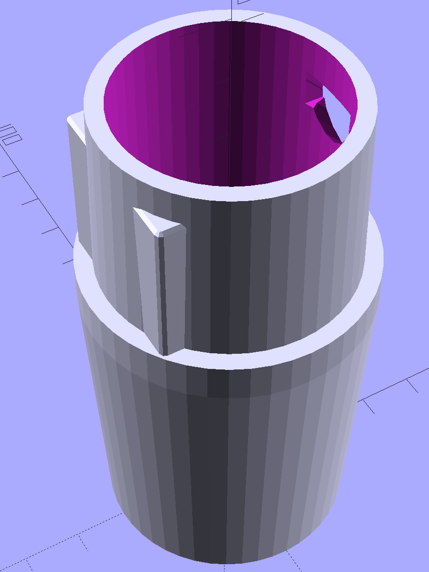
The first step involved modeling the plastic fitting that snaps into the handle:
Which spits out two suitable shapes with the proper positions and alignments:
Kenmore Male Fitting – Latch detail – Solid model
The magic wand for the refrigerator originally slid into the Samsung’s metal pipe, so I put a slightly tapered cylinder inside a somewhat more tapered exterior (which seems chunky enough to withstand my flailing around under the refrigerator), then topped it off with the male fitting:
Refrigerator Coil Wand Adapter
The Kenmore crevice tool snaps under the gargantuan plastic handle, which limits it to being 6.5 inches long, totally unable to reach into any of the nontrivial crevices around here, and in the way when it’s not being used. Some rummaging turned up a longer crevice tool from the Electrolux That Came With The House™, an old-school tool that slipped over its pipe. Modeling a straight cylinder inside a tapered cylinder that fits the tool didn’t take long:
Crevice Tool Adapter
Flushed with success, I found a smaller floor brush than the new Kenmore, with dimensions similar to the Electrolux snout, so another module appeared:
Floor Brush Adapter
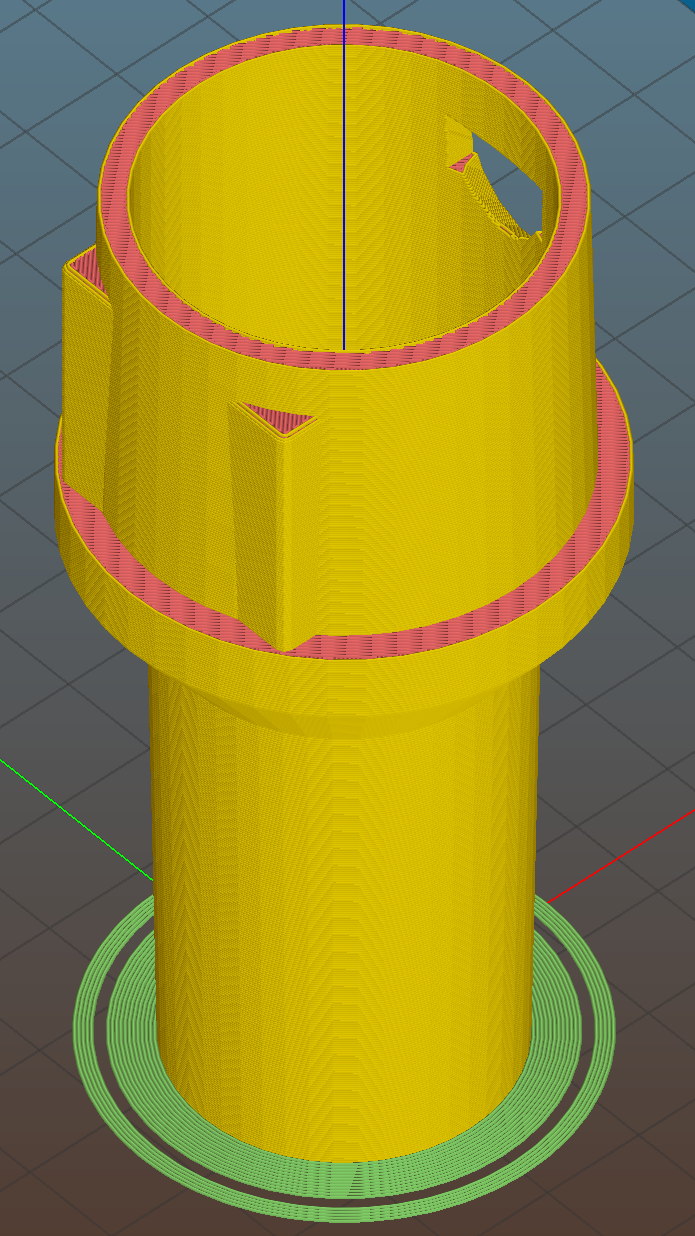
All of them build with the latch end upward to avoid needing support structure, with a 5 mm brim for good platform adhesion:
Floor Brush Adapter – Slic3r preview
I printed them during the PDS Mini Maker Faire as examples of Useful Things You Can Do With a 3D Printer:
Kenmore Vacuum Cleaner – Tool Adapters
As I pointed out to nearly everybody, the Big Lie about 3D printing is that you’ll just download somebody else’s model to solve your problem. In general, that won’t work, because nobody else has your problem; if you can’t do solid modeling, there’s no point in you having a 3D printer. There’s also no point in going to Kinko’s to get a standardized 3D printed doodad, because you can just order a better-looking injection-molded part directly from Sears (or an aftermarket source) and be done with it.
I loves me some good OpenSCAD action on my Makergear M2, though…
The OpenSCAD source code:
// Kenmore vacuum cleaner nozzle adapters
// Ed Nisley KE4ZNU November 2015
// Layout options
Layout = "CreviceTool"; // MaleFitting CoilWand FloorBrush CreviceTool
//- Extrusion parameters must match reality!
// Print with +1 shells and 3 solid layers
ThreadThick = 0.25;
ThreadWidth = 0.40;
HoleWindage = 0.2;
function IntegerMultiple(Size,Unit) = Unit * ceil(Size / Unit);
Protrusion = 0.1; // make holes end cleanly
//----------------------
// Dimensions
ID1 = 0; // for tapered tubes
ID2 = 1;
OD1 = 2;
OD2 = 3;
LENGTH = 4;
OEMTube = [35.0,35.0,41.7,40.5,30.0]; // main fitting tube
EndStop = [OEMTube[ID1],OEMTube[ID2],47.5,47.5,6.5]; // flange at end of main tube
FittingOAL = OEMTube[LENGTH] + EndStop[LENGTH];
$fn = 12*4;
//----------------------
// Useful routines
module PolyCyl(Dia,Height,ForceSides=0) { // based on nophead's polyholes
Sides = (ForceSides != 0) ? ForceSides : (ceil(Dia) + 2);
FixDia = Dia / cos(180/Sides);
cylinder(r=(FixDia + HoleWindage)/2,
h=Height,
$fn=Sides);
}
//-------------------
// Male fitting on end of Kenmore tools
// This slides into the end of the handle or wand and latches firmly in place
module MaleFitting() {
Latch = [40,11.5,5.0]; // rectangle latch opening
EntryAngle = 45; // latch entry ramp
EntrySides = 16;
EntryHeight = 15.0; // lower edge on *inside* of fitting
KeyRadius = 1.0;
translate([0,0,6.5])
difference() {
union() {
cylinder(d1=OEMTube[OD1],d2=OEMTube[OD2],h=OEMTube[LENGTH]); // main tube
hull() // insertion guide
for (i=[-(6.0/2 - KeyRadius),(6.0/2 - KeyRadius)],
j=[-(28.0/2 - KeyRadius),(28.0/2 - KeyRadius)],
k=[-(26.0/2 - KeyRadius),(26.0/2 - KeyRadius)])
translate([(i - (OEMTube[ID1]/2 + OEMTube[OD1]/2)/2 + 6.0/2),j,(k + 26.0/2 - 1.0)])
sphere(r=KeyRadius,$fn=8);
translate([0,0,-EndStop[LENGTH]]) // wand tube butts against this
cylinder(d=EndStop[OD1],h=EndStop[LENGTH] + Protrusion);
}
translate([0,0,-OEMTube[LENGTH]]) // main bore
cylinder(d=OEMTube[ID1],h=2*OEMTube[LENGTH] + 2*Protrusion);
            translate([0,-11.5/2,23.0 - 5.0])                                    // latch opening
                cube(Latch);

            translate([OEMTube[ID1]/2 + EntryHeight/tan(90-EntryAngle),0,0])    // latch ramp
                translate([(Latch[1]/cos(180/EntrySides))*cos(EntryAngle)/2,0,(Latch[1]/cos(180/EntrySides))*sin(EntryAngle)/2])
                    rotate([0,-EntryAngle,0])
                        intersection() {
                            rotate(180/EntrySides)
                                PolyCyl(Latch[1],Latch[0],EntrySides);
                            translate([-(2*Latch[0])/2,0,-Protrusion])
                                cube(2*Latch[0],center=true);
                        }
}
}
//-------------------
// Refrigerator evaporator coil wand
module CoilWand() {
union() {
translate([0,0,50.0])
rotate([180,0,0])
difference() {
cylinder(d1=EndStop[OD1],d2=42.0,h=50.0);
translate([0,0,-Protrusion])
cylinder(d1=35.0,d2=35.8,h=100);
}
translate([0,0,50.0 - Protrusion])
MaleFitting();
}
}
//-------------------
// Refrigerator evaporator coil wand
module FloorBrush() {
union() {
translate([0,0,60.0])
rotate([180,0,0])
difference() {
union() {
cylinder(d1=EndStop[OD1],d2=32.4,h=10.0);
translate([0,0,10.0 - Protrusion])
cylinder(d1=32.4,d2=30.7,h=50.0 + Protrusion);
}
translate([0,0,-Protrusion])
cylinder(d1=28.0,d2=24.0,h=100);
}
translate([0,0,60.0 - Protrusion])
MaleFitting();
}
}
//-------------------
// Crevice tool
module CreviceTool() {
union() {
translate([0,0,60.0])
rotate([180,0,0])
difference() {
union() {
cylinder(d1=EndStop[OD1],d2=32.0,h=10.0);
translate([0,0,10.0 - Protrusion])
cylinder(d1=32.0,d2=30.4,h=50.0 + Protrusion);
}
translate([0,0,-Protrusion])
cylinder(d1=28.0,d2=24.0,h=100);
}
translate([0,0,60.0 - Protrusion])
MaleFitting();
}
}
//----------------------
// Build it!
if (Layout == "MaleFitting")
MaleFitting();
if (Layout == "CoilWand")
CoilWand();
if (Layout == "FloorBrush")
FloorBrush();
if (Layout == "CreviceTool")
CreviceTool();
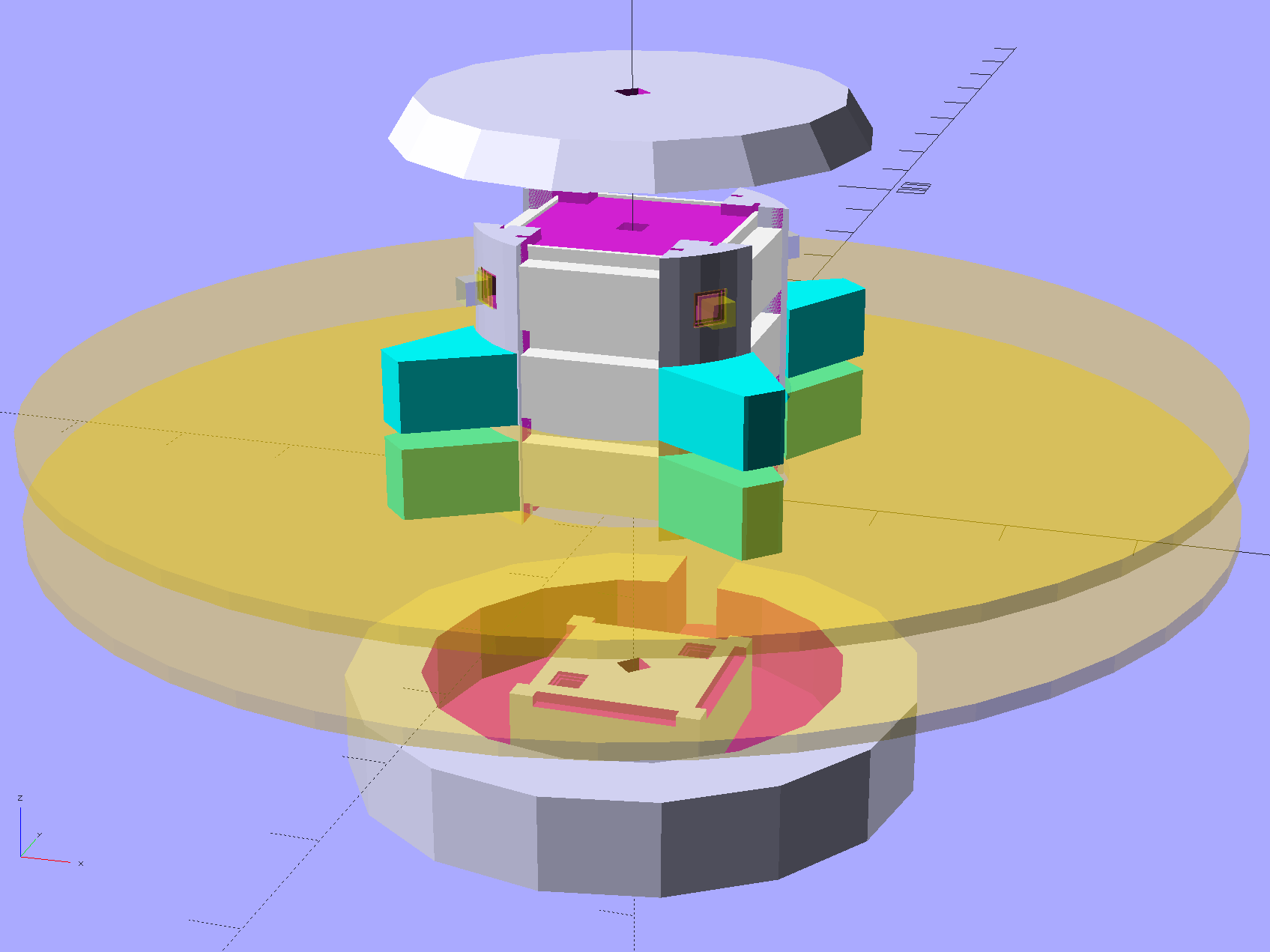
Harvesting a stack of hard drive platters and discovering that four Neopixel strips could stand vertically inside the central hole suggested this overall structure:
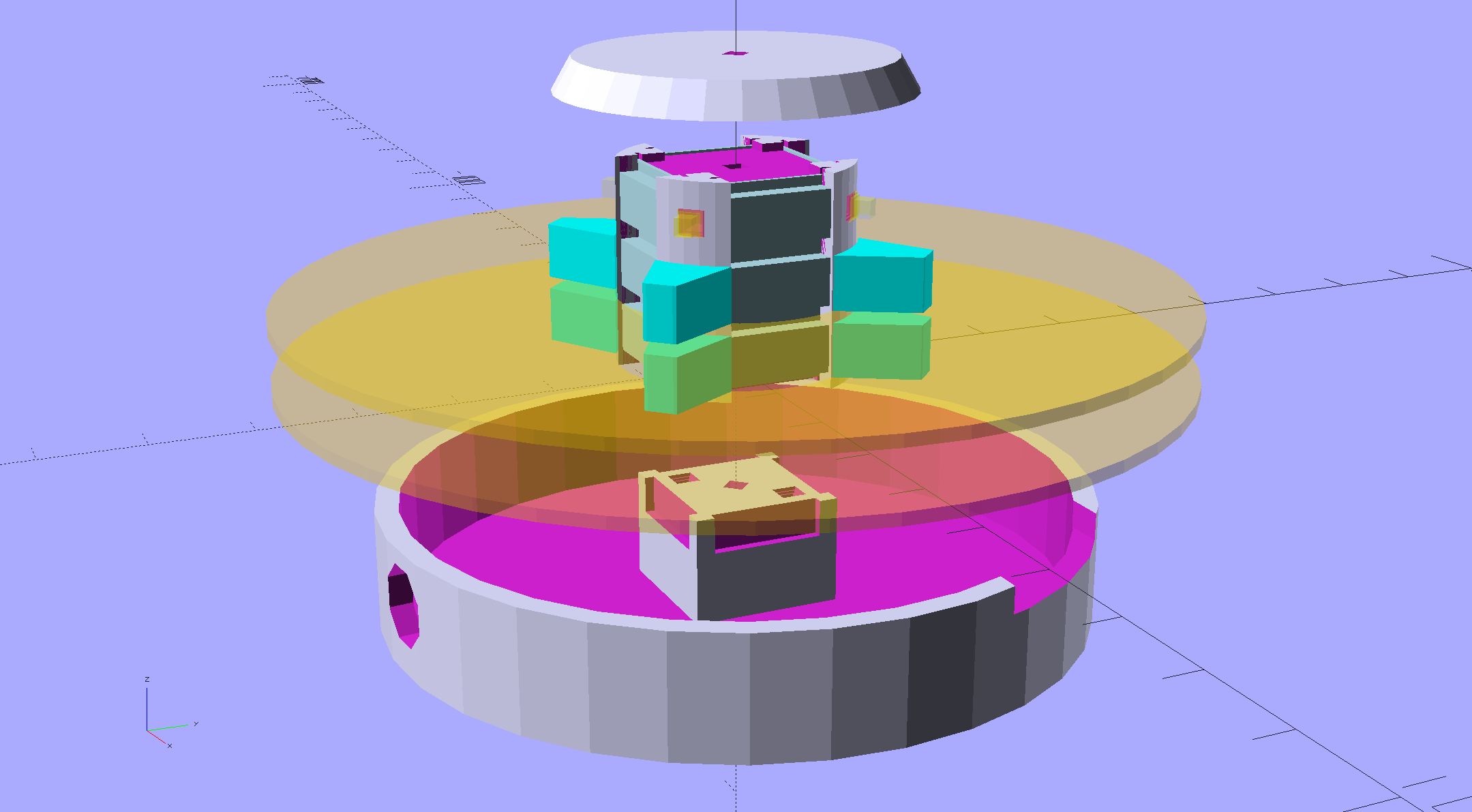
Hard Drive Mood Light – solid model – Show view
The model includes a parameter for the number of strips, but not everything respects that. I’m not sure I’ll ever make a three-LED column and five strips won’t fit, so it probably doesn’t matter.
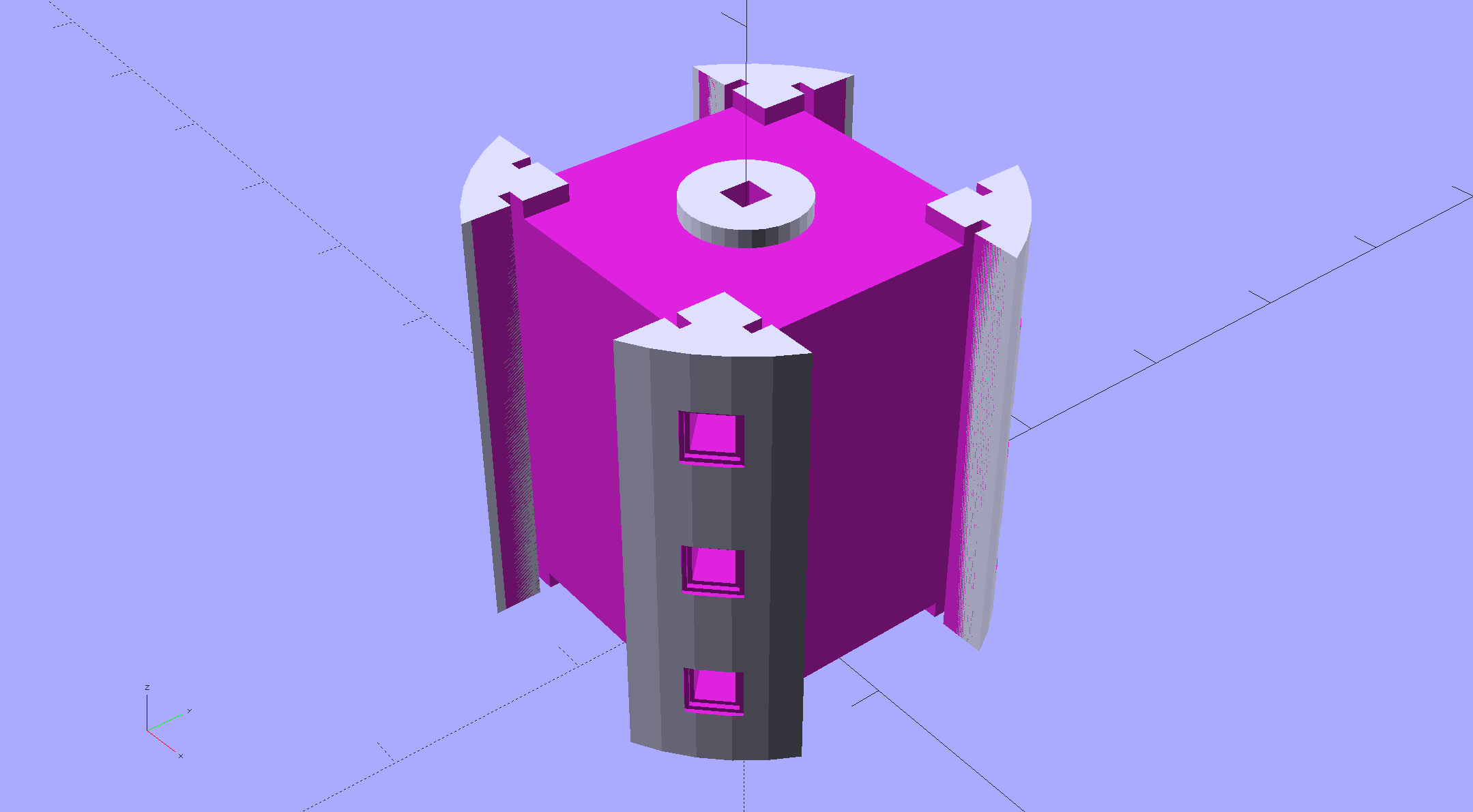
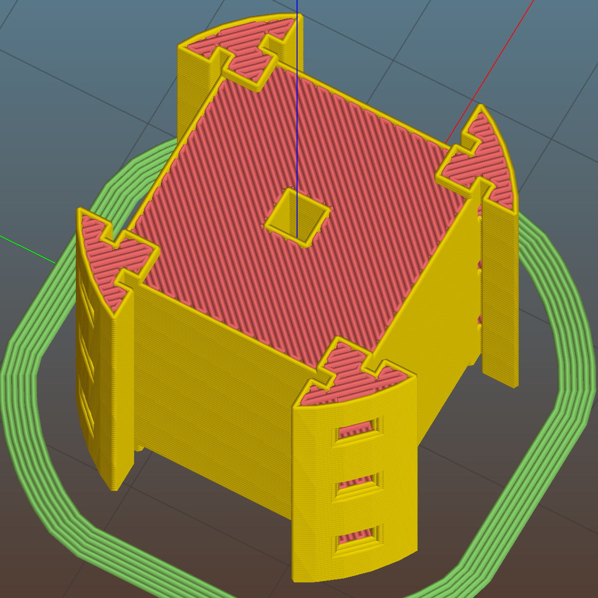
The central pillar holds everything together:
Hard Drive Mood Light – solid model – Pillar
The Neopixel strips slide into those slots, which turned out to be too small to actually print, because the molten plastic pretty much squeezed the slots closed. Some deft pull saw action enlarged them enough to pass the strips, at the cost of tedious hand-fitting and considerable hidden ugliness. Printing the slots slightly larger bangs against the (lack of) printer resolution, because there’s not much wiggle room between the tiny slots and the outer diameter of the column:
Hard Drive Mood Light – Pillar – Slic3r preview
The three alignment pin holes along each edge sit 6.944 mm on center, which is what you get when you divide the nominal 1 meter strip length by 144 Neopixels. I’m using knockoff Neopixels from halfway around the planet, but they’re probably pretty close to the real thing (also from halfway around the planet, I’m sure).
All those parts laid out on the platform, along with a fourth set of spacers in case I drop one:
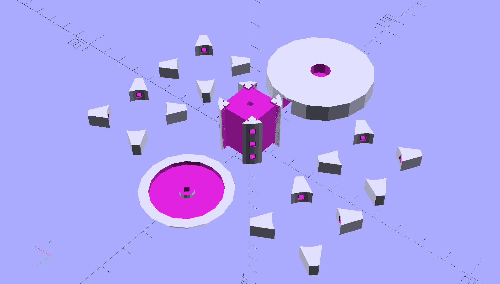
Hard Drive Mood Light – solid model – Build view
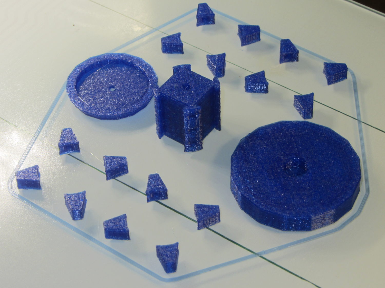
And they print in cyan PETG just like you’d expect:
Hard Drive Mood Light – parts on platform
The round base (on the right) prints bottom-side-up, with bridging from the rim to the central pillar, and came out looking just fine. The top doesn’t have the central post and the pillar doesn’t have the top recess shown in the model: those tweaks will appear in the next iteration.
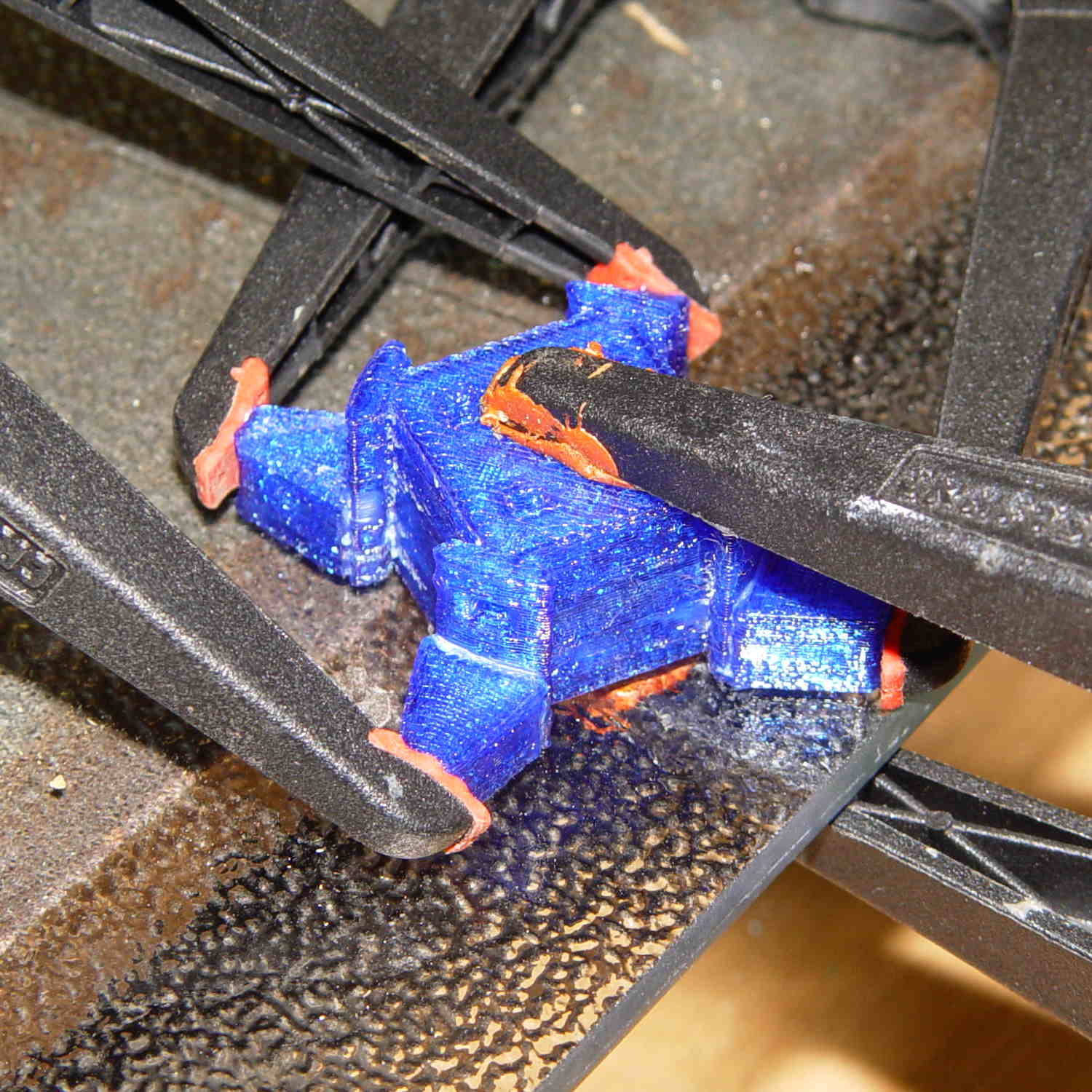
Each tiny triangular spacer gets an alignment pin glued into its inner surface, then four of them get glued to the pillar. This crash test dummy pillar worked out the dimensions, so it’s squat and ugly:
Hard Drive Platter Mood Light – pillar gluing
It’s clamped to a glass plate (smooth side up!) to force the spacers onto on a plane, with the other clamps smashing them against the pillar. All the other spacers get glued in situ atop each platter as it’s installed, which is a definite downside.
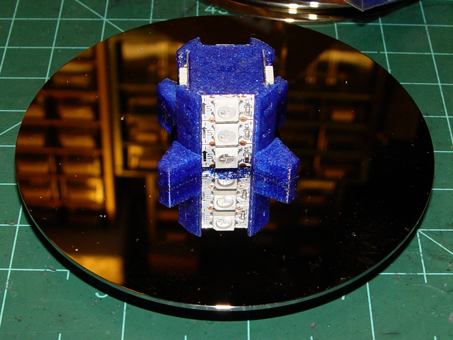
Installing the Neopixels before assembling the platters seemed to be the right way to go:
Hard Drive Mood Light – first platter assembly
After that, just stack ’em up:
Hard Drive Mood Light – top Neopixels
I dry-assembled the upper two spacer sets, so I could pull it apart in case that seemed necessary. Turned out to be a good idea.
And then screw the lid on top to see what it looks like:
Hard Drive Mood Light – trial assembly
That top screw should be a pan-head or something similarly smooth, rather than a random PC case screw. The sacrificial hard drives provided a bunch of Torx screws that would surely look better; most are far too small.
I thought a taller stack would be appropriate, but I kinda like the short, squat aspect ratio.
Now for some wiring…
The OpenSCAD source code:
// Hard Drive Platter Mood Light
// Ed Nisley KE4ZNU November 2015

Layout = "Show";					// Build Show Pixel LEDString Platters Pillar Spacers TopCap Base

ShowDisks = 2;						// number of disks in Show layout

//- Extrusion parameters must match reality!

ThreadThick = 0.20;
ThreadWidth = 0.40;

HoleWindage = 0.2;

Protrusion = 0.1;			// make holes end cleanly

inch = 25.4;

function IntegerMultiple(Size,Unit) = Unit * ceil(Size / Unit);

//----------------------
// Dimensions

ID = 0;
OD = 1;
LENGTH = 2;

Platter = [25.0,95.0,1.27];						// hard drive platters

LEDStringCount = 3;								// number of LEDs on each strip (Show mode looks odd for less than 3)
LEDStripCount = 4;								// number of strips (verify locating pin holes & suchlike)

WireSpace = 1.0;								// allowance for wiring along strip ends

BaseSize = [40,14,3.0];							// overall base plate outside engine controller slot

Pixel = [13.0, 1000 / 144, 0.5];				// smallest indivisible unit of LED strip
PixelMargin = [1.0, 1.0, 2.0];					// LED and circuitry atop the strip

BeamAngle = 120;								// LED viewing angle
BeamShape = [
	[0,0],
	[Platter[OD]*cos(BeamAngle/2),-Platter[OD]*sin(BeamAngle/2)],
	[Platter[OD]*cos(BeamAngle/2), Platter[OD]*sin(BeamAngle/2)]
];

PillarSides = 12*4;

PillarCore = Platter[ID] - 2*(Pixel[2] + PixelMargin[2] + 2.0);		// LED channel distance across pillar centerline
PillarLength = LEDStringCount*Pixel[1] + Platter[LENGTH];
echo(str("Pillar core size: ",PillarCore));
echo(str("      ... length:"),PillarLength);

Cap = [Platter[ID] + 4.0,Platter[ID] + 4.0 + 10*2*ThreadWidth,2*WireSpace + 6*ThreadThick];		// cap over top of pillar
CapSides = 16;

Base = [Platter[ID] + 10.0,0.5*Platter[OD],8.0];
BaseSides = 16;

Screw = [2.0,3.0,20.0];							// screws used to secure cap & pillar

Spacer = [Platter[ID],(Platter[ID] + 2*8),(Pixel[1] - Platter[LENGTH])];
echo(str("Spacer  OD: ",Spacer[OD]));
echo(str(" ... thick:",Spacer[LENGTH]));

LEDStripProfile = [
	[0,0],
	[Pixel[0]/2,0],
	[Pixel[0]/2,Pixel[2]],
	[(Pixel[0]/2 - PixelMargin[0]),Pixel[2]],
	[(Pixel[0]/2 - PixelMargin[0]),(Pixel[2] + PixelMargin[2])],
	[-(Pixel[0]/2 - PixelMargin[0]),(Pixel[2] + PixelMargin[2])],
	[-(Pixel[0]/2 - PixelMargin[0]),Pixel[2]],
	[-Pixel[0]/2,Pixel[2]],
	[-Pixel[0]/2,0]
];

//----------------------
// Useful routines

module PolyCyl(Dia,Height,ForceSides=0) {			// based on nophead's polyholes

  Sides = (ForceSides != 0) ? ForceSides : (ceil(Dia) + 2);

  FixDia = Dia / cos(180/Sides);

  cylinder(r=(FixDia + HoleWindage)/2,
		h=Height,
	$fn=Sides);
}

//- Locating pin hole with glue recess
//  Default length is two pin diameters on each side of the split

PinOD = 1.70;

module LocatingPin(Dia=PinOD,Len=0.0) {

	PinLen = (Len != 0.0) ? Len : (4*Dia);

	translate([0,0,-ThreadThick])
		PolyCyl((Dia + 2*ThreadWidth),2*ThreadThick,4);

	translate([0,0,-2*ThreadThick])
		PolyCyl((Dia + 1*ThreadWidth),4*ThreadThick,4);

	translate([0,0,-(PinLen/2 + ThreadThick)])
		PolyCyl(Dia,(PinLen + 2*ThreadThick),4);

}
//----------------------
// Pieces

//-- LED strips

module OnePixel() {

	render()
		rotate([-90,0,0]) rotate(180)				// align result the way you'd expect from the dimensions
			difference() {
				linear_extrude(height=Pixel[1],convexity=3)
					polygon(points=LEDStripProfile);
				translate([-Pixel[0]/2,Pixel[2],-PixelMargin[0]])
					cube([Pixel[0],2*PixelMargin[2],2*PixelMargin[0]]);
				translate([-Pixel[0]/2,Pixel[2],Pixel[1]-PixelMargin[0]])
					cube([Pixel[0],2*PixelMargin[2],2*PixelMargin[0]]);
			}
}

module LEDString(n = LEDStringCount) {

	for (i=[0:n-1])
		translate([0,i*Pixel[1]])
//			resize([0,Pixel[1] + 2*Protrusion,0])
				OnePixel();
}

//-- Stack of hard drive platters

module Platters(n = LEDStringCount + 1) {

	color("gold",0.4)
	for (i=[0:n-1]) {
		translate([0,0,i*Pixel[1]])
			difference() {
				cylinder(d=Platter[OD],h=Platter[LENGTH],center=false,$fn=PillarSides);
				cylinder(d=Platter[ID],h=3*Platter[LENGTH],center=true,$fn=PillarSides);
			}
	}
}

//-- Pillar holding the LED strips

module Pillar() {

	difflen = PillarLength + 2*Protrusion;

//	render(convexity=5)
	difference() {
		linear_extrude(height=PillarLength,convexity=4)
			difference() {
				rotate(180/(12*4))
					circle(d=Platter[ID] - 1*ThreadWidth,$fn=PillarSides);

				for (i=[0:LEDStripCount-1]) 					// clearance for LED beamwidth, may not actually cut surface
					rotate(i*360/LEDStripCount)
						translate([PillarCore/2,0,0])
							polygon(points=BeamShape);

				for (i=[0:LEDStripCount-1])						// LED front clearance
					rotate(i*360/LEDStripCount)
						translate([(PillarCore/2 + Pixel[2]),(Pixel[0] - 2*PixelMargin[0])/2])
							rotate(-90)
								square([Pixel[0] - 2*PixelMargin[0],Platter[ID]]);

			}

		for (i=[0:LEDStripCount-1])								// LED strip slots
			rotate(i*360/LEDStripCount)
				translate([PillarCore/2,0,-Protrusion])
					linear_extrude(height=difflen,convexity=2)
						rotate(-90)
							polygon(points=LEDStripProfile);

		for (i=[0,90])											// wiring recess on top surface
			rotate(i)
				translate([0,0,(PillarLength - (WireSpace/2 - Protrusion))])
					cube([(PillarCore + 2*Protrusion),Pixel[0] - 2*PixelMargin[0],WireSpace],center=true);

		for (i=[0:LEDStripCount-1])								// wiring recess on bottom surface
			rotate(i*90)
				translate([PillarCore/2 - (WireSpace - Protrusion)/2,0,WireSpace/2 - Protrusion])
					cube([WireSpace + Protrusion,Pixel[0] - 2*PixelMargin[0],WireSpace],center=true);

		for (j=[0:LEDStringCount-1])							// platter spacer alignment pins
			for (i=[0:LEDStripCount-1])
				rotate(i*360/LEDStripCount + 180/LEDStripCount)
					translate([(Platter[ID] - 1*ThreadWidth)/2,0,(j*Pixel[1] + Pixel[1]/2 + Platter[LENGTH]/2)])
						rotate([0,90,0])
							rotate(45)
								LocatingPin();

		translate([0,0,-Protrusion])							// central screw hole
			rotate(180/4)
				PolyCyl(Screw[ID],difflen,4);

		if (false)
		for (i=[-1,1])											// vertical wire channels
			rotate(i*360/LEDStripCount + 180/LEDStripCount)
				translate([PillarCore/2 - 2.0,0,-Protrusion])
					PolyCyl(2.0,difflen,4);

		for (i=[-1,1])											// locating pins
			rotate(i*360/LEDStripCount - 180/LEDStripCount)
				translate([PillarCore/2 - 2.0,0,0])
					LocatingPin();
	}
}

//-- Spacers to separate platters

module Spacers() {

	difference() {
		linear_extrude(height=Spacer[LENGTH],convexity=4)
			difference() {
				rotate(180/PillarSides)
					circle(d=Spacer[OD],$fn=PillarSides);

				for (i=[0:LEDStripCount-1]) 					// clearance for LED beamwidth, may not actually cut surface
					rotate(i*360/LEDStripCount)
						translate([PillarCore/2,0,0])
							polygon(points=BeamShape);

				for (i=[0:LEDStripCount-1])						// LED front clearance
					rotate(i*360/LEDStripCount)
						translate([(PillarCore/2 + Pixel[2]),(Pixel[0] - 2*PixelMargin[0])/2])
							rotate(-90)
								square([Pixel[0] - 2*PixelMargin[0],Platter[ID]]);


				rotate(180/PillarSides)
					circle(d=Spacer[ID],$fn=PillarSides);		// central pillar fits in the hole
			}

		for (i=[0:LEDStripCount-1])
			rotate(i*360/LEDStripCount + 180/LEDStripCount)
				translate([Platter[ID]/2,0,(Pixel[1] - Platter[LENGTH])/2])
					rotate([0,90,0])
						rotate(45)
							LocatingPin();

	}
}

//-- Cap over top of pillar

module TopCap() {

	difference() {
		cylinder(d1=(Cap[OD] + Cap[ID])/2,d2=Cap[OD],h=Cap[LENGTH],$fn=CapSides);		// outer lid

		translate([0,0,-Protrusion])
			PolyCyl(Screw[ID],Cap[LENGTH] + WireSpace + Protrusion,4);					// screw hole

		translate([0,0,Cap[LENGTH] - 2*WireSpace])
			difference() {
				cylinder(d=Cap[ID],h=2*Cap[LENGTH],$fn=CapSides);						// cutout
				cylinder(d=2*Screw[OD],h=Cap[LENGTH],$fn=CapSides);						// boss
			}

		translate([0,0,Cap[LENGTH] - ThreadThick])
			cylinder(d=Cap[ID]/2,h=ThreadThick + Protrusion,$fn=CapSides);				// recess boss
	}
}

//-- Base below pillar

module Base() {

	SideWidth = 0.5*Base[OD]*sin(180/BaseSides);						// close enough

	difference() {
		union() {
			difference() {
				cylinder(d=Base[OD],h=Base[LENGTH],$fn=BaseSides);			// outer base

				translate([0,0,6*ThreadThick])								// main cutout
					cylinder(d=Base[ID],h=Base[LENGTH],$fn=BaseSides);

				translate([-SideWidth/2,0,6*ThreadThick]) 					// cable port
					cube([SideWidth,Base[OD],Base[LENGTH]]);
			}

			translate([0,0,Base[LENGTH]/2])									// pillar support is recessed below rim
				cube([PillarCore,PillarCore,Base[LENGTH] - ThreadThick],center=true);
		}

		for (i=[0:LEDStripCount-1])											// wiring recesses
			rotate(i*90)
				translate([PillarCore/2 - (WireSpace - Protrusion)/2,0,Base[LENGTH] - WireSpace/2])
					cube([WireSpace + Protrusion,PillarCore - 4*WireSpace,WireSpace],center=true);

		translate([0,0,-Protrusion])
			PolyCyl(Screw[ID],2*Base[LENGTH],4);						// screw hole

		translate([0,0,-Protrusion])									// screw head recess
			PolyCyl(8.5,5.0 + Protrusion,$fn=6);

		for (i=[-1,1])													// locating pins
			rotate(i*360/LEDStripCount - 180/LEDStripCount)
				translate([PillarCore/2 - 2.0,0,Base[LENGTH] - ThreadThick])
					LocatingPin();

	}

}

//----------------------
// Build it

if (Layout == "Pixel")
	OnePixel();

if (Layout == "LEDString")
	LEDString(LEDStringCount);

if (Layout == "Platters")
	Platters(LEDStringCount + 1);

if (Layout == "Pillar")
	Pillar(LEDStringCount);

if (Layout == "TopCap")
	TopCap();

if (Layout == "Base")
	Base();

if (Layout == "Spacers")
	Spacers();

if (Layout == "Show") {
	Pillar();

	for (i=[0:LEDStripCount-1])											// LED strips
		rotate(i*360/LEDStripCount)
			translate([PillarCore/2,0,Platter[LENGTH]/2])
				rotate([90,0,90])
					color("lightblue") LEDString();
	if (true)
	for (j=[0:max(1,ShowDisks - 2)])									// spacers
		translate([0,0,(j*Pixel[1] + Platter[LENGTH])])
			color("cyan") Spacers();

	for (j=[0:max(2,ShowDisks - 2)])										// spacer alignment pins
		for (i=[0:LEDStripCount-1])
			rotate(i*360/LEDStripCount + 180/LEDStripCount)
				translate([(Platter[ID] - 1*ThreadWidth)/2,0,(j*Pixel[1] + Pixel[1]/2 + Platter[LENGTH]/2)])
					rotate([0,90,0])
						rotate(45)
							 color("Yellow",0.25) LocatingPin(Len=4);
	translate([0,0,PillarLength + 3*Cap[LENGTH]])
		rotate([180,0,0])
			TopCap();

	translate([0,0,-3*Base[LENGTH]])
		Base();

	if (ShowDisks > 0)
		Platters(ShowDisks);

}

// Ad-hoc build layout

if (Layout == "Build") {
	Pillar();

	translate([0,Cap[OD],0])
		TopCap();

	translate([0,-Base[OD],Base[LENGTH]])
		rotate([0,180,0])
			Base();

	Ybase = Spacer[OD] * (LEDStringCount%2 ? (LEDStringCount - 1) : (LEDStringCount - 2)) / 4;
	for (i=[0:LEDStringCount])										// build one extra set of spacers!
		translate([(i%2 ? 1 : -1)*(Spacer[OD] + Base[OD])/2,		// alternate X sides to shrink Y space
				   (i%2 ? i-1 : i)*Spacer[OD]/2 - Ybase,			// same Y for even-odd pairs in X
				   0])
			Spacers();
}
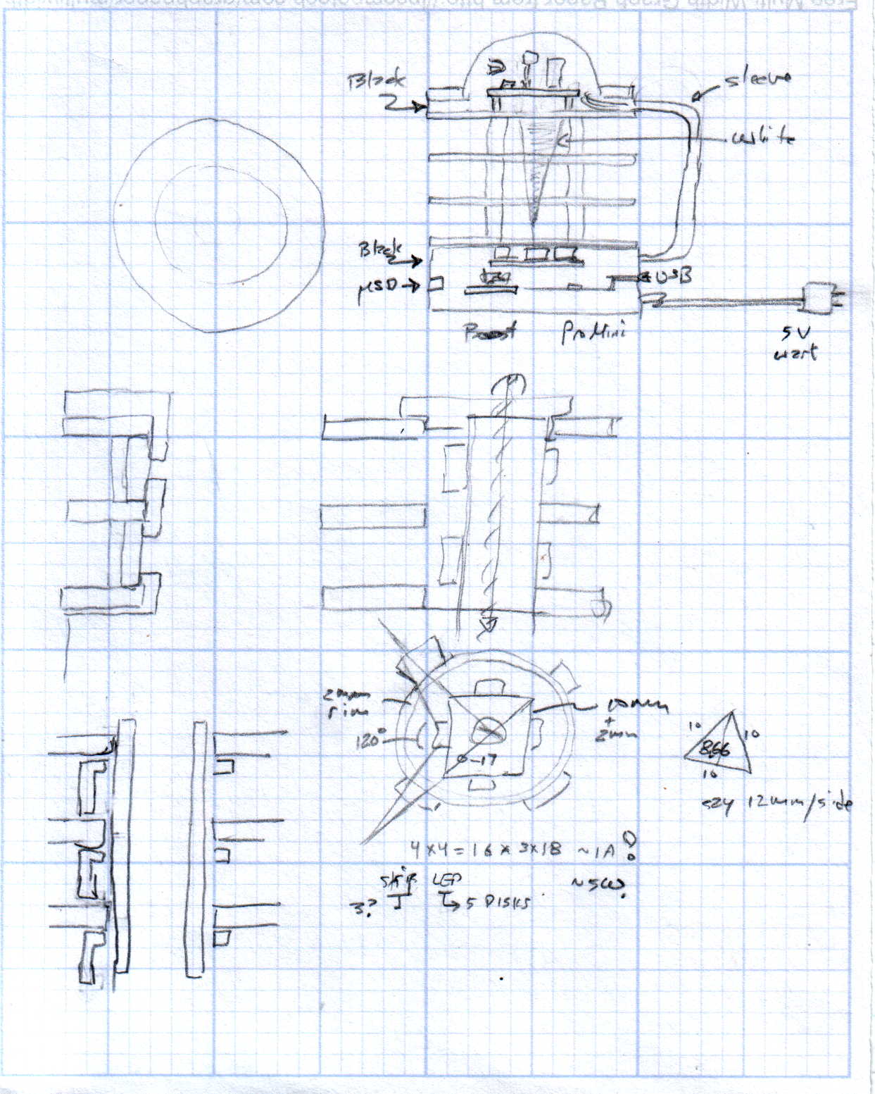
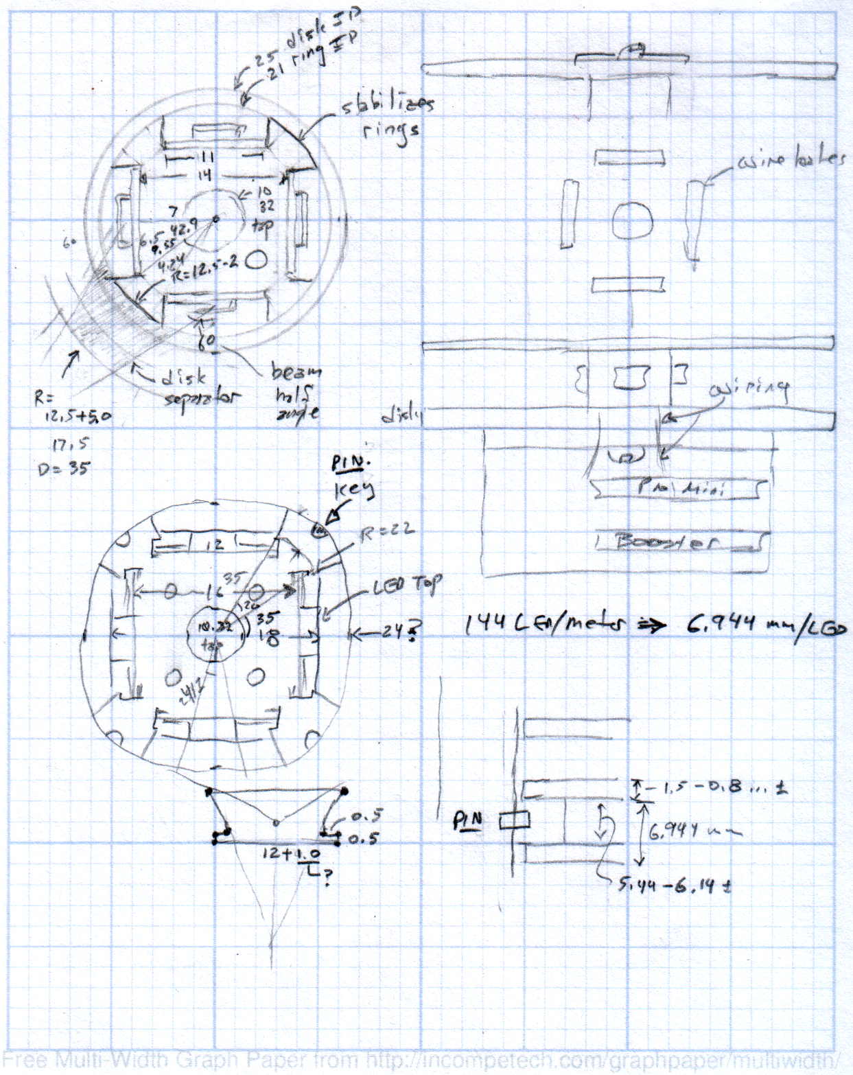
The original doodles showing this might work, along with some ideas that wouldn’t:
In the (admittedly unlikely) event you’re in the neighborhood today, visit the Poughkeepsie Mini MakerFaire. I’ll be doing a “Practical 3D Printing” show-n-tell in one of the tiny music practice rooms in the main hallway, handing out tchochkes, and generally talking myself hoarse. The HP 7475A plotter will be cranking out Superforumulas next door, too, because everybody loves watching a plotter.
Usually, I print dump trucks or some such, but yesterday I hammered out the models for two adapters that mate the new vacuum cleaner to some old tools, so I’ll be doing live-fire production printing. I’m sure you can get adapters on Amazon, but what’s the fun in that?
The magic wand that sucks dust off the evaporator coils under the refrigerator slides into the bottom end of this one:
Refrigerator Coil Wand Adapter
And the snout of this slides into the tiny floor brush that fits into spots the new one can’t reach:
Floor Brush Adapter
And, with a Faire wind in my sails, perhaps I can run off the bits required for a hard drive mood light:
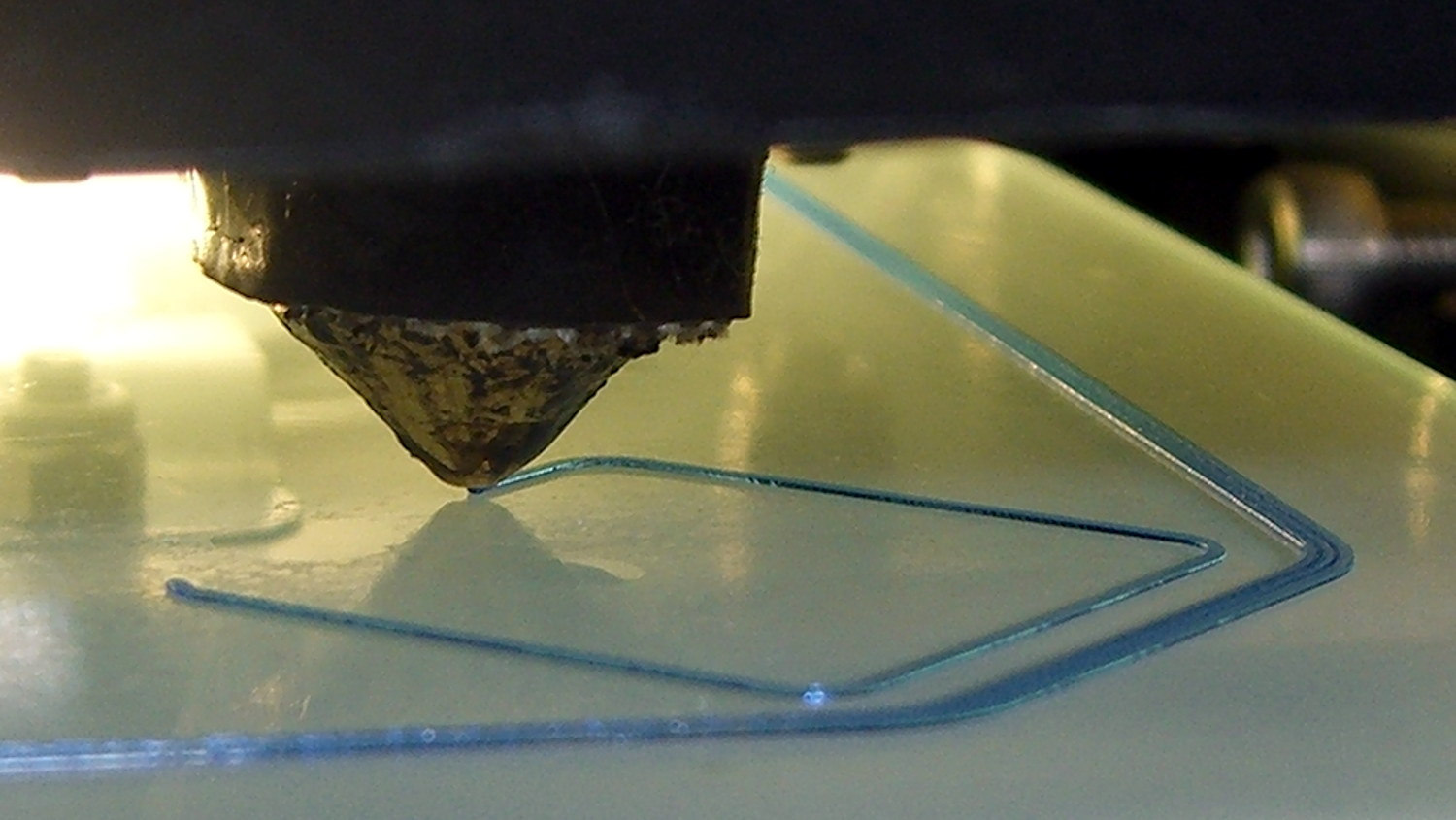
Here’s what the 0.35 mm diameter nozzle of my Makergear M2 looks like when printing a 0.40×0.25 mm thread on borosilicate glass with a coating of hairspray:
M2 V4 nozzle – thinwall box first layer
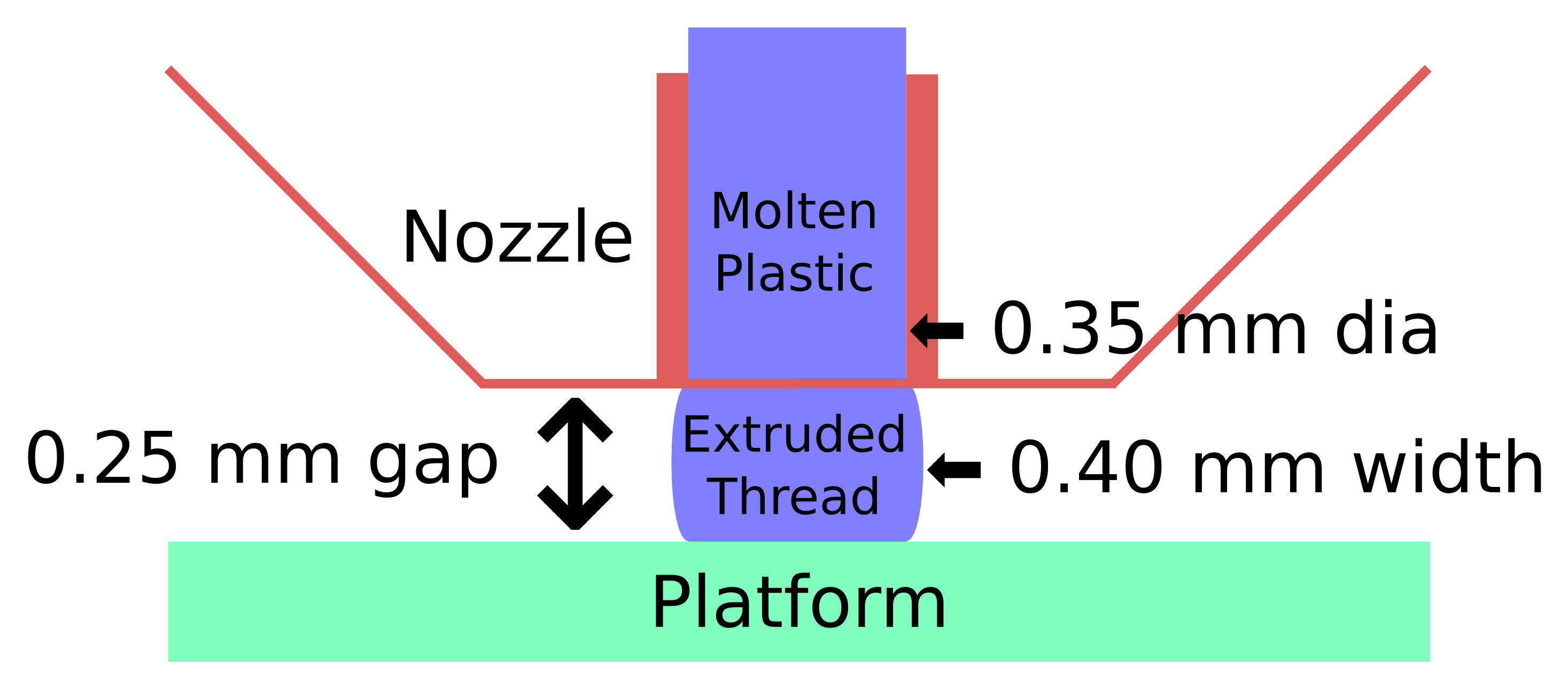
The dimensions:
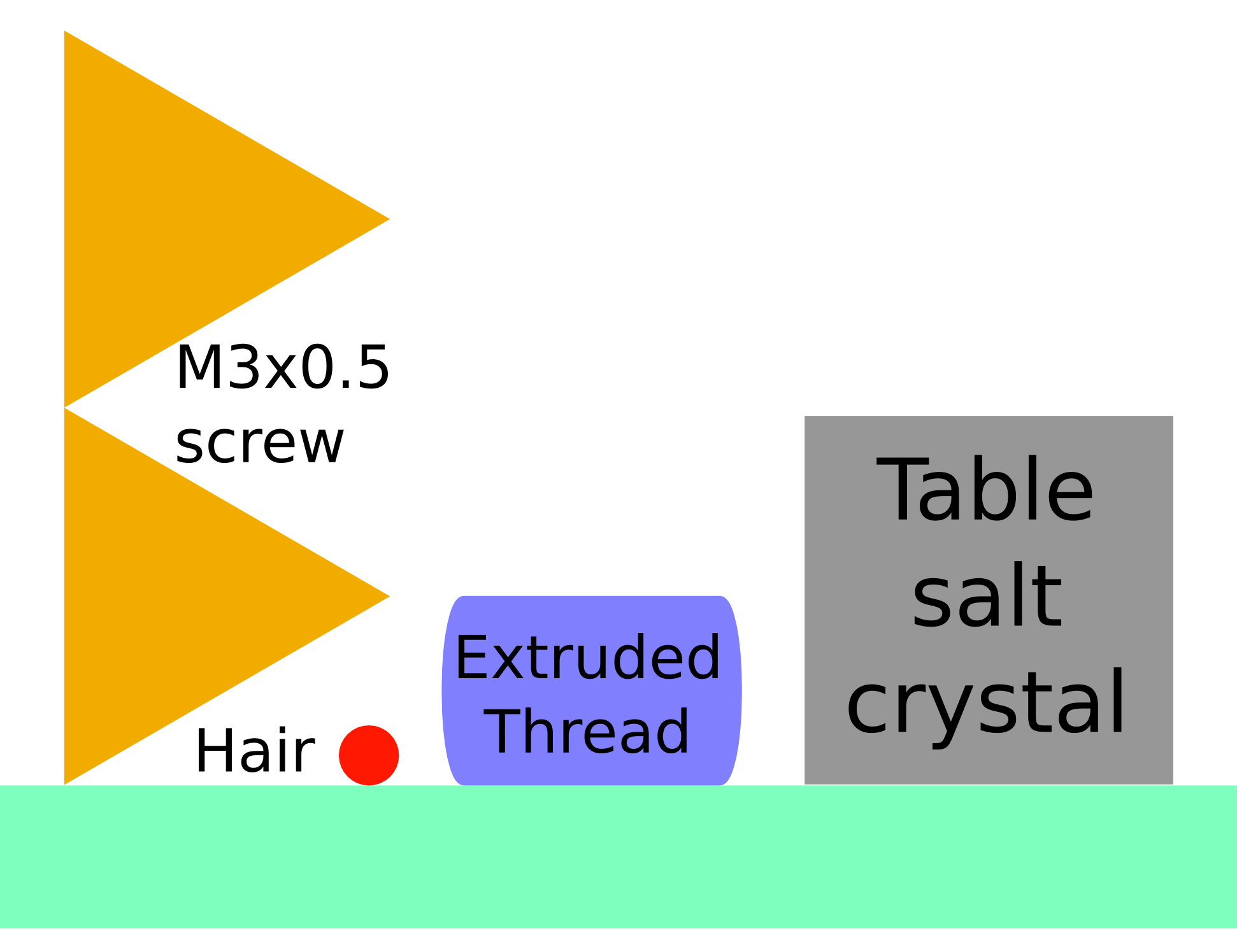
Extrusion Dimensions
Some common household objects at the same scale:
Objects vs Thread Comparison
The accuracy required is literally hair-fine: being off by the diameter of the hair on your head can wreck the first layer of the printed object.
One turn of the M3 screws supporting the M2 platform move the mounting point by twice the thread thickness. Their positions on the platform amplify the motion by about a factor of two, so if you’re tweaking the screws by more than 1/6 turn at a time, you’re overdoing it.
For first-layer nozzle-to-platform distance adjustment:
If it increases by 0.25 mm, the plastic won’t touch the platform
If it decreases by 0.25 mm, the plastic won’t come out of the nozzle
For platform alignment:
If your printer can’t maintain the proper gap to within ±0.10 mm across the entire platform, it won’t produce accurate results
Works for me, anyhow. All I do is slice whatever object I’ve just designed, turn the M2 on, and print it. No muss, no fuss, no wasted motion: It Just Works.
The sketches come from my Digital Machinist column (DM 10.4). They’ve been covering a bunch of 3D printing topics, so if you’re interested in that kind of stuff…