The Smell of Molten Projects in the Morning

Ed Nisley's Blog: Shop notes, electronics, firmware, machinery, 3D printing, laser cuttery, and curiosities. Contents: 100% human thinking, 0% AI slop.

Tag: M2

Using and tweaking a Makergear M2 3D printer

  • Improved Gas Cartridge Fins

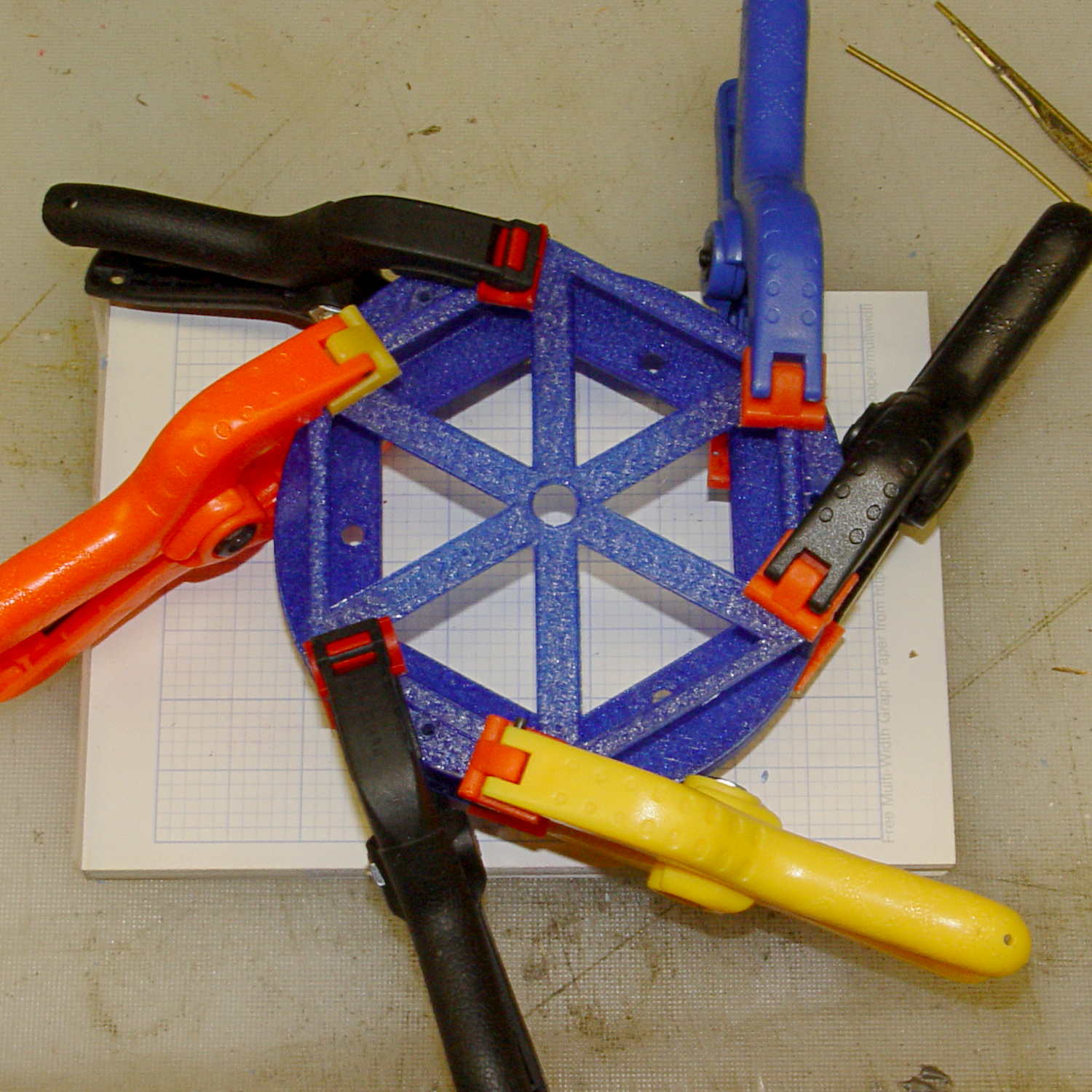
    A trio of N2O cartridges / capsules made their way into the Basement Laboratory and cried out to be fitted with fins:

    N2O Capsule Fins - installed
    N2O Capsule Fins – installed

    My original model tinkered up a cartridge from solid object primitives, but I’ve since discovered that cheating produces a much better and faster and easier result for cylindrical objects:
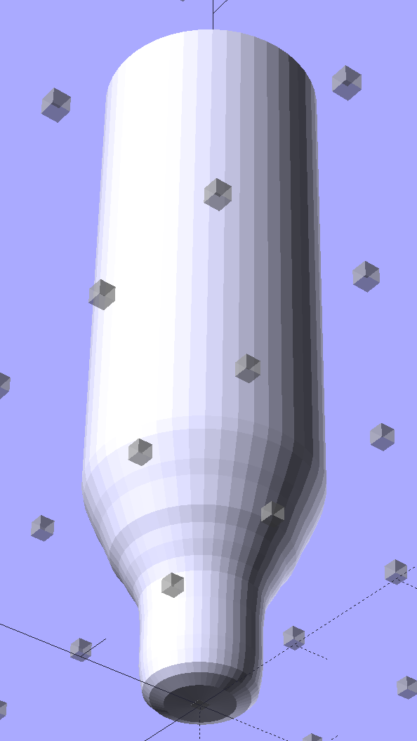
    N2O Capsule - solid model - bottom view
    N2O Capsule – solid model – bottom view

    The trick is getting an image of the original object from the side, taken from far enough away to flatten the perspective:
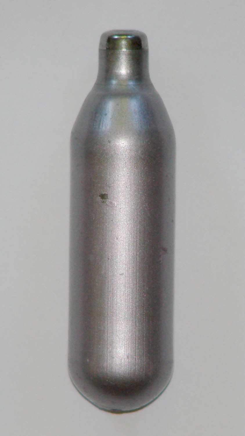
    N2O capsule - side view
    N2O capsule – side view

    Then overlay and scale a grid to match the actual length:

    N2O capsule - grid overlay
    N2O capsule – grid overlay

    The grid has 1 mm per minor square, centered along the cartridge’s axis, and zeroed at the tip; I rotated the cartridge image by half a degree to line it up with the grid.

    Print it out on actual paper so you can eyeball the measurements and write ’em where you need ’em:

    N2O capsule - grid overlay - printed
    N2O capsule – grid overlay – printed

    Which becomes an OpenSCAD polygon definition:

    RADIUS = 0;				// subscript for radius values
    HEIGHT = 1;				//   ... height above Z=0 at seal flange
    
    //-- N2O 8 g capsule
    
    CartridgeOutline = [			// X values = measured radius, Y as distance from tip
    	[0.0,0.0],					//  0 cartridge seal tip
    	[2.5,0.1],					//  1 seal disk
    	[3.5,0.5],[4.0,1.0],		//  2 tip end
    	[4.2,2.0],[4.3,3.0],		//  4 tip
    	[4.3,6.0],					//  6 chamfer
    	[4.5,8.0],					//  7 taper
    	[4.9,9.0],					//  8
    	[5.5,10.0],					//  9
    	[6.0,11.0],					// 10
    	[6.7,12.0],					// 11
    	[7.1,13.0],					// 12
    	[7.5,14.0],					// 13
    	[8.0,15.0],					// 14
    	[8.4,16.0],					// 15
    	[8.8,17.0],					// 16
    	[9.0,18.0],[9.0,58.0],		// 17 body
    	[0.0,65.0]					// 19 dummy end cone
    	];
    
    TipLength = CartridgeOutline[6][HEIGHT];
    TipOD = 2*CartridgeOutline[5][RADIUS];
    	
    BodyOD = 2*CartridgeOutline[17][RADIUS];
    BodyOAL = CartridgeOutline[19][HEIGHT];
    

    Because the rounded end of the cartridge doesn’t matter, I turned it into a cone.

    Twirl that around the Z axis and It Just Works:

    module Cartridge() {
    
     rotate_extrude($fn=CartridgeSides)
     polygon(points=CartridgeOutline);
    
    }
    

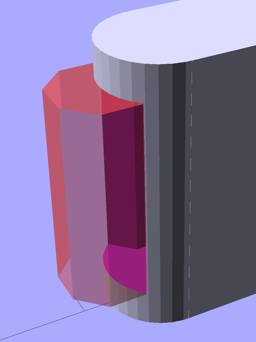
    Which then punches a matching dent in the fin structure:

    Gas Capsule Fins - Slic3r preview
    Gas Capsule Fins – Slic3r preview

    The lead picture doesn’t quite match the Slic3r preview, as I found the single-width diagonal fins weren’t strong enough. Making them two (nominal) threads wide lets Slic3r lay down three thinner threads in the same space:

    Gas Capsule Fins - thicker - Slic3r preview
    Gas Capsule Fins – thicker – Slic3r preview

    That’s letting Slic3r automagically determine the infill and perimeter thread width to make the answer come out right. As nearly as I can tell, the slicing algorithms have become smart enough to get the right answer nearly all of the time, so I can-and-should relinquish more control over the details.

    The OpenSCAD source code:

    // CO2 capsule tail fins
    // Ed Nisley KE4ZNU - October 2015
    
    Layout = "Build"; // Show Build FinBlock Cartridge Fit
    
    //-------
    //- Extrusion parameters must match reality!
    // Print with +0 shells and 3 solid layers
    
    ThreadThick = 0.25;
    ThreadWidth = 0.40;
    
    HoleWindage = 0.2;
    
    Protrusion = 0.1; // make holes end cleanly
    
    function IntegerMultiple(Size,Unit) = Unit * ceil(Size / Unit);
    
    //-------
    // Capsule dimensions
    
    CartridgeSides = 12*4; // number of sides
    
    RADIUS = 0; // subscript for radius values
    HEIGHT = 1; // ... height above Z=0 at seal flange
    
    //-- N2O 8 g capsule
    
    RW = HoleWindage/2; // enlarge radius by just enough
    
    CartridgeOutline = [ // X values = measured radius, Y as distance from tip
     [0.0,0.0], // 0 cartridge seal tip
     [2.5 + RW,0.1], // 1 seal disk
     [3.5 + RW,0.5],[4.0 + RW,1.0], // 2 tip end
     [4.2 + RW,2.0],[4.3 + RW,3.0], // 4 tip
     [4.3 + RW,6.0], // 6 chamfer
     [4.5 + RW,8.0], // 7 taper
     [4.9 + RW,9.0], // 8
     [5.5 + RW,10.0], // 9
     [6.0 + RW,11.0], // 10
     [6.7 + RW,12.0], // 11
     [7.1 + RW,13.0], // 12
     [7.5 + RW,14.0], // 13
     [8.0 + RW,15.0], // 14
     [8.4 + RW,16.0], // 15
     [8.8 + RW,17.0], // 16
     [9.0 + RW,18.0],[9.0 + RW,58.0], // 17 body
     [0.0,65.0] // 19 dummy end cone
     ];
    
    TipLength = CartridgeOutline[6][HEIGHT];
    TipOD = 2*CartridgeOutline[5][RADIUS];
    
    CylinderBase = CartridgeOutline[17][HEIGHT];
    
    BodyOD = 2*CartridgeOutline[17][RADIUS];
    BodyOAL = CartridgeOutline[19][HEIGHT];
    
    //-------
    // Fin dimensions
    
    FinThick = 1.5*ThreadWidth; // outer square
    StrutThick = 2.0*ThreadWidth; // diagonal struts
    
    FinSquare = 1.25*BodyOD;
    FinTaperLength = sqrt(2)*FinSquare/2 - sqrt(2)*FinThick - ThreadWidth;
    
    FinBaseLength = 0.7 * CylinderBase;
    FinTop = 0.9*CylinderBase;
    
    //-------
    
    module PolyCyl(Dia,Height,ForceSides=0) { // based on nophead's polyholes
    
     Sides = (ForceSides != 0) ? ForceSides : (ceil(Dia) + 2);
    
     FixDia = Dia / cos(180/Sides);
    
     cylinder(r=(FixDia + HoleWindage)/2,h=Height,$fn=Sides);
    }
    
    module ShowPegGrid(Space = 10.0,Size = 1.0) {
    
     Range = floor(50 / Space);
    
     for (x=[-Range:Range])
     for (y=[-Range:Range])
     translate([x*Space,y*Space,Size/2])
     %cube(Size,center=true);
    
    }
    
    //-------
    // CO2 cartridge outline
    
    module Cartridge() {
    
     rotate_extrude($fn=CartridgeSides)
     polygon(points=CartridgeOutline);
    
    }
    
    //-------
    // Diagonal fin strut
    
    module FinStrut() {
     intersection() {
     rotate([90,0,45])
     translate([0,0,-StrutThick/2])
     linear_extrude(height=StrutThick)
     polygon(points=[
     [0,0],
     [FinTaperLength,0],
     [FinTaperLength,FinBaseLength],
     [0,(FinBaseLength + FinTaperLength)]
     ]);
     translate([0,0,FinTop/2])
     cube([2*FinSquare,2*FinSquare,FinTop], center=true);
     }
    }
    
    //-------
    // Fin outline
    
    module FinBlock() {
     
    $fn=12;
     render(convexity = 4)
     union() {
     translate([0,0,FinBaseLength/2])
     difference() {
     intersection() {
     minkowski() {
     cube([FinSquare - 2*ThreadWidth,
     FinSquare - 2*ThreadWidth,
     FinBaseLength],center=true);
     cylinder(r=FinThick,h=Protrusion,$fn=8);
     }
     cube([2*FinSquare,2*FinSquare,FinBaseLength],center=true);
     }
     difference() {
     cube([(FinSquare - 2*FinThick),
     (FinSquare - 2*FinThick),
     (FinBaseLength + 2*Protrusion)],center=true);
     for (Index = [0:3])
     rotate(Index*90)
     translate([(FinSquare/2 - FinThick),(FinSquare/2 - FinThick),0])
     cylinder(r=2*StrutThick,h=(FinBaseLength + 2*Protrusion),center=true,$fn=16);
     }
     }
     
     for (Index = [0:3])
     rotate(Index*90)
     FinStrut();
     
     rotate(180/12)
     cylinder(d=IntegerMultiple(TipOD + 6*ThreadWidth,ThreadWidth),h=TipLength);
     }
    }
    
    //-------
    // Fins
    
    module FinAssembly() {
    
     difference() {
     FinBlock();
     translate([0,0,2*ThreadThick]) // add two layers to close base cylinder
     Cartridge();
     }
    
    }
    
    module FinFit() {
    
     translate([0,0.75*BodyBaseLength,2*ThreadThick])
     rotate([90,0,0])
     difference() {
     translate([-FinSquare/2,-2*ThreadThick,0])
     cube([IntegerMultiple(FinSquare,ThreadWidth),
     4*ThreadThick,
     1.5*BodyBaseLength]);
     translate([0,0,5*ThreadWidth])
     Cartridge();
     }
    
    
    }
    
    //-------
    // Build it!
    
    ShowPegGrid();
    
    if (Layout == "FinStrut")
     FinStrut();
    
    if (Layout == "FinBlock")
     FinBlock();
    
    if (Layout == "Cartridge")
     Cartridge();
    
    if (Layout == "Show") {
     FinAssembly();
     color("LightYellow") Cartridge();
    }
    
    if (Layout == "Fit")
     FinFit();
    
    if (Layout == "Build")
     FinAssembly();
    
  • Victoreen 710-104 Ionization Chamber: Improved Circuit Board Holder

    The alignment pin holes between the ionization can lid and the board supports:

    Victoreen 710-104 Ionization Chamber Fittings - Alignment pin detail
    Victoreen 710-104 Ionization Chamber Fittings – Alignment pin detail

    … turned out to be a bit shorter than they should be, so I changed two lines of code and ran off another set:

    Electrometer amp - chamber cap - on platform
    Electrometer amp – chamber cap – on platform

    Which glued together perfectly, albeit with Too Many Clamps:

    Electrometer amp - chamber cap - gluing
    Electrometer amp – chamber cap – gluing

    The (minutely revised) OpenSCAD source code:

    // Victoreen 710-104 Ionization Chamber Fittings
    // Ed Nisley KE4ZNU August 2015
    
    Layout = "Show";
    					// Show - assembled parts
    					// Build - print can parts + shield
    					// BuildShield - print just the shield
    					// BuildHolder - print just the can cap & PCB base
    					// CanCap - PCB insulator for 6-32 mounting studs
    					// CanBase - surrounding foot for ionization chamber
    					// CanRim - generic surround for either end of chamber
    					// PCB - template for cutting PCB sheet
    					// PCBBase - holder for PCB atop CanCap
    					// Shield - electrostatic shield shell
    
    //- Extrusion parameters must match reality!
    //  Print with 2 shells and 3 solid layers
    
    ThreadThick = 0.25;
    ThreadWidth = 0.40;
    
    HoleWindage = 0.2;
    
    Protrusion = 0.1;			// make holes end cleanly
    
    AlignPinOD = 1.75;			// assembly alignment pins = filament dia
    
    inch = 25.4;
    
    function IntegerMultiple(Size,Unit) = Unit * ceil(Size / Unit);
    
    //- Screw sizes
    
    Tap4_40 = 0.089 * inch;
    Clear4_40 = 0.110 * inch;
    Head4_40 = 0.211 * inch;
    Head4_40Thick = 0.065 * inch;
    Nut4_40Dia = 0.228 * inch;
    Nut4_40Thick = 0.086 * inch;
    Washer4_40OD = 0.270 * inch;
    Washer4_40ID = 0.123 * inch;
    
    
    //----------------------
    // Dimensions
    
    OD = 0;											// name the subscripts
    LENGTH = 1;
    
    Chamber = [91.0,38];							// Victoreen ionization chamber dimensions
    
    Stud = [										// stud welded to ionization chamber lid
    	[6.5,IntegerMultiple(0.8,ThreadThick)],		// flat head -- generous clearance
    	[4.0,9.5],									// 6-32 screw -- ditto
    ];
    NumStuds = 3;									// this really isn't much of a variable...
    StudAngle = 360/NumStuds;
    StudSides = 6;									// for hole around stud
    
    BCD = 2.75 * inch;								// mounting stud bolt circle diameter
    
    PlateThick = 2.0;								// minimum layer atop and below chamber ends
    RimHeight = 4.0;								// extending along chamber perimeter
    WallHeight = RimHeight + PlateThick;
    WallThick = 3.0;								// thick enough to be sturdy & printable
    CapSides = 8*6;									// must be multiple of 4 & 3 to make symmetries work out right
    
    RimOD = Chamber[OD] + 2*WallThick;
    
    echo(str("Rim OD: ",RimOD));
    
    //PCBFlatsOD = 82.0;							// desired hex dia flat-to-flat
    PCBFlatsOD = floor(RimOD*cos(30)) - 2.0;		//  .. maximum possible
    //PCBFlatsOD = floor(Chamber[OD]*cos(30)) - 2.0;	//  .. chamber fitting
    PCBClearance = ThreadWidth;						// clearance beyond each flat for mounting
    
    PCBThick = 1.1;
    PCBActual = [PCBFlatsOD/cos(30),PCBThick];		// OD = tip-to-tip
    PCBCutter = [(PCBFlatsOD + 2*PCBClearance)/cos(30),PCBThick - ThreadThick];		// OD = tip-to-tip dia + clearance
    
    PCBSize = str(PCBFlatsOD, " mm");
    echo(str("Actual PCB across flats: ",PCBFlatsOD));
    echo(str(" ... tip-to-tip dia: ",PCBActual[OD]));
    echo(str(" ... thickness: ",PCBActual[LENGTH]));
    
    HolderHeight = 13.0 + PCBCutter[LENGTH];		// thick enough for PCB to clear studs + batteries
    HolderShelf = 2.0;								// shelf under PCB edge
    HolderTrim = 5.0;								// remove end of holder to clear PCB edge solder blobs
    echo(str("Holder trim distance: ",HolderTrim));
    HolderTrimAngle = StudAngle/2 - 2*atan(HolderTrim*cos(StudAngle/2)/(PCBActual[OD]/2));	// atan is close for small angles
    echo(str(" ... angle: ",HolderTrimAngle));
    
    PinAngle = 15;									// alignment pin angle on either side of holder screw
    
    echo(str("PCB holder across flats: ",PCBCutter[OD]*cos(30)));
    echo(str(" ... height: ",HolderHeight));
    
    ShieldInset = 0.5;								// shield inset from actual PCB flat
    ShieldWall = 2.0;								// wall thickness
    ShieldLid = 6*ThreadThick;						// top thickness (avoid one infill layer)
    Shield = [(PCBFlatsOD - 2*ShieldInset)/ cos(30),40.0];		// electrostatic shield shell dimensions
    
    TextSize = 4;
    TextCharSpace = 1.05;
    TextLineSpace = TextSize + 2;
    TextDepth = 1*ThreadThick;
    
    //----------------------
    // Useful routines
    
    module PolyCyl(Dia,Height,ForceSides=0) {			// based on nophead's polyholes
    
      Sides = (ForceSides != 0) ? ForceSides : (ceil(Dia) + 2);
    
      FixDia = Dia / cos(180/Sides);
    
      cylinder(r=(FixDia + HoleWindage)/2,
    			h=Height,
    		$fn=Sides);
    }
    
    //- Locating pin hole with glue recess
    //  Default length is two pin diameters on each side of the split
    
    module LocatingPin(Dia=AlignPinOD,Len=0.0) {
    	
    	PinLen = (Len != 0.0) ? Len : (4*Dia);
    	
    	translate([0,0,-ThreadThick])
    		PolyCyl((Dia + 2*ThreadWidth),2*ThreadThick,4);
    
    	translate([0,0,-2*ThreadThick])
    		PolyCyl((Dia + 1*ThreadWidth),4*ThreadThick,4);
    		
    	translate([0,0,-Len/2])
    		PolyCyl(Dia,Len,4);
    
    }
    
    module ShowPegGrid(Space = 10.0,Size = 1.0) {
    
      RangeX = floor(100 / Space);
      RangeY = floor(125 / Space);
      
    	for (x=[-RangeX:RangeX])
    		for (y=[-RangeY:RangeY])
    		translate([x*Space,y*Space,Size/2])
    			%cube(Size,center=true);
    }
    
    //-----
    
    module CanRim(BaseThick) {
    	
    	difference() {
    		cylinder(d=Chamber[OD] + 2*WallThick,h=(WallHeight + BaseThick),$fn=CapSides);
    		translate([0,0,BaseThick])
    			PolyCyl(Chamber[OD],Chamber[LENGTH],CapSides);
    	}
    	
    }
    
    module CanCap() {
    	
    	difference() {
    		CanRim(PlateThick + Stud[0][LENGTH]);
    		
    		translate([0,0,-Protrusion])											// central cutout
    			rotate(180/6)
    				cylinder(d=BCD,h=Chamber[LENGTH],$fn=6);						//  ... reasonable size
    			
    		for (i=[0:(NumStuds - 1)])												// stud clearance holes
    			rotate(i*StudAngle)
    				translate([BCD/2,0,0])
    					rotate(180/StudSides) {
    						translate([0,0,PlateThick])
    							PolyCyl(Stud[0][OD],Chamber[LENGTH],StudSides);
    						translate([0,0,-Protrusion])
    							PolyCyl(Stud[1][OD],Chamber[LENGTH],StudSides);
    					}
    					
    		for (i=[0:(NumStuds - 1)], j=[-1,1])									// PCB holder alignment pins
    			rotate(i*StudAngle + j*PinAngle + 60)
    				translate([Chamber[OD]/2,0,0])
    					rotate(180/4 - j*PinAngle)
    						LocatingPin(Len=2*(PlateThick + Stud[0][LENGTH]) - 4*ThreadThick);
    						
    		translate([-(BCD/2),0,-Protrusion])
    			rotate(90) mirror() 
    				linear_extrude(height=(ThreadThick + Protrusion))
    				text(PCBSize,size=6,font="Liberation Mono:style=bold",halign="center",valign="center");
    	}
    
    }
    
    module CanBase() {
    	
    	difference() {
    		CanRim(PlateThick);
    		translate([0,0,-Protrusion])
    			PolyCyl(Chamber[OD] - 2*RimHeight,Chamber[LENGTH],CapSides);
    	}
    }
    
    module PCBTemplate() {
    	
    	CutLen = 10*PCBActual[LENGTH];
    	
    	difference() {
    		cylinder(d=PCBActual[OD],h=PCBActual[LENGTH],$fn=6);		// actual PCB size
    		translate([0,0,-Protrusion])
    			cylinder(d=8,h=CutLen,$fn=12);
    		if (true)
    			for (i=[0:5])											// empirical cutouts
    				rotate(i*60 + 30)
    					translate([PCBFlatsOD/3,0,-Protrusion])
    						rotate(60)
    							cylinder(d=0.43*PCBActual[OD],h=CutLen,$fn=3);
    							
    		translate([PCBActual[OD]/4,0,(PCBActual[LENGTH] - ThreadThick)])
    			linear_extrude(height=(ThreadThick + Protrusion),convexity=1)
    			text(PCBSize,size=4,font="Liberation Mono:style=bold",halign="center",valign="center");
    							
    	}
    }
    
    module PCBBase() {
    
    	intersection() {
    		difference() {
    			cylinder(d=Chamber[OD] + 2*WallThick,h=HolderHeight,$fn=CapSides);		// outer rim
    			
    			rotate(30) {
    				translate([0,0,-Protrusion])										// central hex
    					cylinder(d=(PCBActual[OD] - HolderShelf/cos(30) - HolderShelf/cos(30)),h=2*HolderHeight,$fn=6);
    					
    				translate([0,0,HolderHeight - PCBCutter[LENGTH]])					// hex PCB recess
    					cylinder(d=PCBCutter[OD],h=HolderHeight,$fn=6);
    					
    				for (i=[0:NumStuds - 1])											// PCB retaining screws
    					rotate(i*StudAngle + 180/(2*NumStuds))
    						translate([(PCBCutter[OD]*cos(30)/2 + Clear4_40/2 + ThreadWidth),0,-Protrusion])
    							rotate(180/6)
    								PolyCyl(Tap4_40,2*HolderHeight,6);
    								
    				for (i=[0:(NumStuds - 1)], j=[-1,1])								// PCB holder alignment pins
    					rotate(i*StudAngle + j*PinAngle + 180/(2*NumStuds))
    						translate([Chamber[OD]/2,0,0])
    							rotate(180/4 - j*PinAngle)
    								LocatingPin(Len=2*(HolderHeight - 4*ThreadThick));
    			}
    			
    			if (false)
    			for (i=[0:NumStuds - 1])
    				rotate(i*StudAngle - StudAngle/2)							// segment isolation - hex sides
    					translate([0,0,-Protrusion]) {
    						linear_extrude(height=2*HolderHeight)
    							polygon([[0,0],[Chamber[OD],0],[Chamber[OD]*cos(180/NumStuds),Chamber[OD]*sin(180/NumStuds)]]);
    					}
    					
    			translate([-(PCBFlatsOD/2 + PCBClearance - HolderShelf),0,HolderHeight/2])
    				rotate([0,90,0]) rotate(90)
    					linear_extrude(height=(ThreadWidth + Protrusion))
    					text(PCBSize,size=6,font="Liberation Mono:style=bold",halign="center",valign="center");
    					
    		}
    		
    		for (i=[0:NumStuds - 1])
    			rotate(i*StudAngle + StudAngle/2 - HolderTrimAngle/2)								// trim holder ends
    				translate([0,0,-Protrusion]) {
    					linear_extrude(height=2*HolderHeight)
    						polygon([[0,0],[Chamber[OD],0],[Chamber[OD]*cos(HolderTrimAngle),Chamber[OD]*sin(HolderTrimAngle)]]);
    				}
    			
    	}
    }
    
    //-- Electrostatic shield
    //		the cutouts are completely ad-hoc
    
    module ShieldShell() {
    	
    CutHeight = 7.0;
    	
    	difference() {
    		cylinder(d=Shield[OD],h=Shield[LENGTH],$fn=6);							// exterior shape
    		
    		translate([0,0,-ShieldLid])												// interior
    			cylinder(d=(Shield[OD] - 2*ShieldWall/cos(30)),h=Shield[LENGTH],$fn=6);
    
    		translate([0,0,Shield[LENGTH] - TextDepth])
    		rotate(180) {
    			translate([0,0.3*Shield[OD] - 0*TextLineSpace,0])
    				linear_extrude(height=(TextDepth + Protrusion))
    					text("Gamma",size=TextSize,spacing=TextCharSpace,font="Liberation:style=bold",halign="center",valign="center");
    			translate([0,0.3*Shield[OD] - 1*TextLineSpace,0])
    				linear_extrude(height=(TextDepth + Protrusion))
    					text("Ionization",size=TextSize,spacing=TextCharSpace,font="Liberation:style=bold",halign="center",valign="center");
    			translate([0,0.3*Shield[OD] - 2*TextLineSpace,0])
    				linear_extrude(height=(TextDepth + Protrusion))
    					text("Amplifier",size=TextSize,spacing=TextCharSpace,font="Liberation:style=bold",halign="center",valign="center");
    			translate([0,-0.3*Shield[OD] + 1*TextLineSpace,0])
    				linear_extrude(height=(TextDepth + Protrusion))
    					text("KE4ZNU",size=TextSize,spacing=TextCharSpace,font="Liberation:style=bold",halign="center",valign="center");
    			translate([0,-0.3*Shield[OD] + 0*TextLineSpace,0])
    				linear_extrude(height=(TextDepth + Protrusion))
    					text("2015-08",size=TextSize,spacing=TextCharSpace,font="Liberation:style=bold",halign="center",valign="center");
    		}
    			
    		translate([Shield[OD]/4 - 20/2,Shield[OD]/2,(CutHeight - Protrusion)/2])	// switch
    			rotate(90)
    				cube([Shield[OD],20,CutHeight + Protrusion],center=true);
    
    		if (false)
    		translate([-Shield[OD]/4 + 5/2,Shield[OD]/2,(CutHeight - Protrusion)/2])	// front
    			rotate(90)
    				cube([Shield[OD],5,CutHeight + Protrusion],center=true);
    
    		translate([-Shield[OD]/2,0,(CutHeight - Protrusion)/2])						// right side
    				cube([Shield[OD],7,CutHeight + Protrusion],center=true);
    
    		translate([0,(Shield[OD]*cos(30)/2 - ThreadWidth),0.75*Shield[LENGTH]])
    			rotate([90,0,180]) rotate(00)
    				linear_extrude(height=(ThreadWidth + Protrusion))
    				text(PCBSize,size=5,font="Liberation Mono:style=bold",halign="center",valign="center");
    	}
    	
    }
    
    //----------------------
    // Build it
    
    ShowPegGrid();
    
    if (Layout == "CanRim") {
    	CanRim();
    }
    
    if (Layout == "CanCap") {
    	CanCap();
    }
    
    if (Layout == "CanBase") {
    	CanBase();
    }
    
    if (Layout == "PCBBase") {
    	PCBBase();
    }
    
    if (Layout == "PCB") {
    	PCBTemplate();
    }
    
    if (Layout == "Shield") {
    	ShieldShell();
    }
    
    if (Layout == "Show") {
    	CanBase();
    	color("Orange",0.5)
    		translate([0,0,PlateThick + Protrusion])
    			cylinder(d=Chamber[OD],h=Chamber[LENGTH],$fn=CapSides);
    	translate([0,0,(2*PlateThick + Chamber[LENGTH] + 2*Protrusion)])
    		rotate([180,0,0])
    			CanCap();
    	translate([0,0,(2*PlateThick + Chamber[LENGTH] + 5.0)])
    		PCBBase();
    	color("Green",0.5)
    		translate([0,0,(2*PlateThick + Chamber[LENGTH] + 7.0 + HolderHeight)])
    			rotate(30)
    				PCBTemplate();
    	translate([0,0,(2*PlateThick + Chamber[LENGTH] + 15.0 + HolderHeight)])
    		rotate(-30)
    			ShieldShell();}
    
    if (Layout == "Build") {
    	
    	translate([-0.50*Chamber[OD],-0.60*Chamber[OD],0])
    		CanCap();
    		
    	if (false)
    		translate([0.55*Chamber[OD],-0.60*Chamber[OD],0])
    			rotate(30)
    				translate([0,0,Shield[LENGTH]])
    					rotate([0,180,0])
    						ShieldShell();
    	if (true)
    		translate([0.55*Chamber[OD],-0.60*Chamber[OD],0])
    			rotate(30)
    				PCBTemplate();
    
    	if (true)
    		translate([-0.25*Chamber[OD],0.60*Chamber[OD],0])
    			CanBase();
    		translate([0.25*Chamber[OD],0.60*Chamber[OD],0])
    			PCBBase();
    }
    
    if (Layout == "BuildHolder") {
    	translate([-0.25*Chamber[OD],0,0])
    		CanCap();
    	translate([0.25*Chamber[OD],0,0])
    		PCBBase();
    }
    
    if (Layout == "BuildShield") {
    	
    	translate([0,0,Shield[LENGTH]])
    		rotate([0,180,0])
    				ShieldShell();
    		
    
    }
    

    Yeah, a Github repo would be nice, but the overhead for one-off models just isn’t worthwhile.

  • Makergear M2: Platform Stability

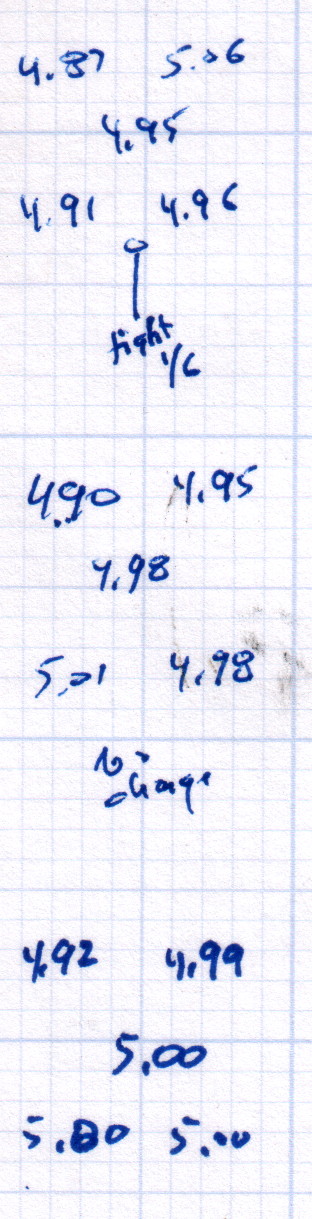
    After replacing that washer, the last step in the platform alignment required 1/6 turn on the front screw between the top two sets of measurements:

    M2 Alignment measurements - 2015-08-09 - 2
    M2 Alignment measurements – 2015-08-09 – 2

    The last two sets show the sample-to-sample variation with no adjustments, which didn’t amount to much.

    Without changing anything else, I then switched from magenta PETG filament to cyan and ran off two more sets of thinwall hollow boxes (in addition to other doodads) over the next two days:

    M2 Alignment measurements - 2015-08-10
    M2 Alignment measurements – 2015-08-10

    A bit less than a month later, after producing several iterations of unrelated doodads:

    M2 Alignment measurements - 2015-09-07
    M2 Alignment measurements – 2015-09-07

    The variation in the center box height from 4.94 mm to 5.00 mm shows that sensing the platform Z-axis position directly on the glass surface actually works the way it should: ±0.03 mm is as good as it gets. Given that my measurement error / eyeballometric averaging on any given box runs around ±0.02 mm, the far corners also seem rock-stable and certainly don’t justify automatic alignment probing and adjustment.

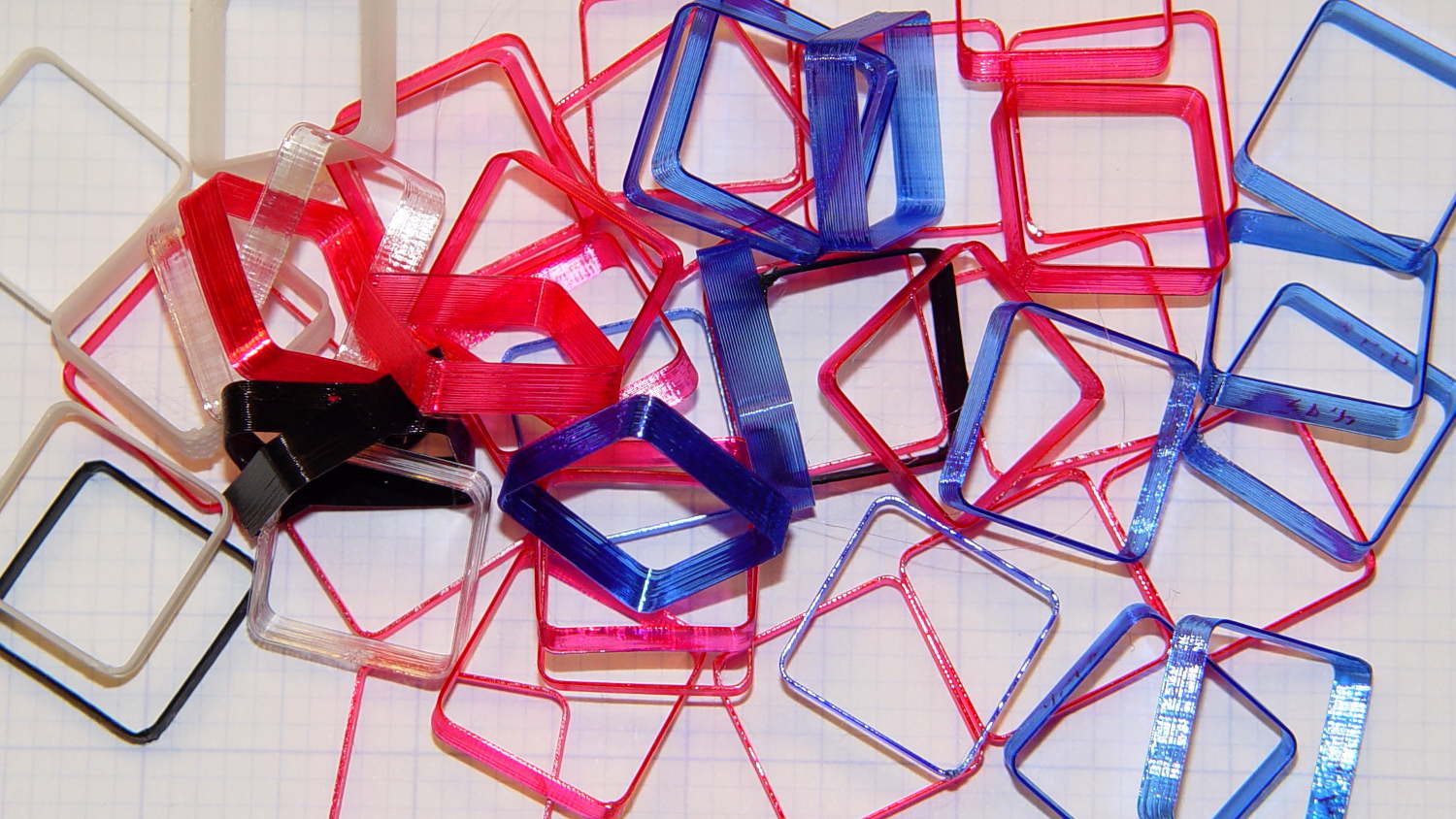
    Thinwall hollow boxes make good handouts at 3D printing presentations…

    Thinwall Hollow Box collection
    Thinwall Hollow Box collection
  • Garden Knife Sheath

    This replaces the transparent acrylic version that’s sure to resurface in the garden:

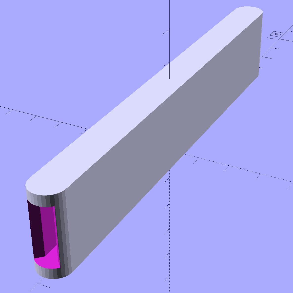
    Garden Knife Sheath - solid model
    Garden Knife Sheath – solid model

    The ends have nice chamfered entrances made from octagons:

    Garden Knife Sheath - entrances - solid model
    Garden Knife Sheath – entrances – solid model

    The thing went away so fast I didn’t get a chance to photograph it, but magenta PETG filament should make it much harder to mislay, out there among the greenery…

    The OpenSCAD source code:

    // Garden Knife Scabbard
    // Ed Nisley KE4ZNU - August 2015
    
    //- Extrusion parameters - must match reality!
    
    ThreadThick = 0.25;
    ThreadWidth = 0.40;
    
    function IntegerMultiple(Size,Unit) = Unit * ceil(Size / Unit);
    
    Protrusion = 0.1;
    
    HoleWindage = 0.2;
    
    //------
    // Dimensions
    
    WallThick = IntegerMultiple(3.0,ThreadWidth);
    
    Blade = [115,1.8,16.0];
    
    Clearance = [10.0,2.0,2.0];
    
    Slot = Blade + Clearance;
    
    Sheath = Slot + [0,2*WallThick,2*WallThick];
    
    //- Build it
    
    
    translate([0,0,Sheath[2]/2])
        difference() {
            union() {
                for (i=[-1,1])
                    translate([i*Sheath[0]/2,0,-Sheath[2]/2])
                        rotate(180/32)
                            cylinder(d=Sheath[1],h=Sheath[2],$fn=32);
                cube(Sheath,center=true);
            }
            cube(Slot + [Slot[0],0,0],center=true);
            for (i=[-1,1])
                translate([i*(Sheath[0]/2 + Sheath[1]/2),0,-Slot[2]/2])
                    rotate(180/8)
                        cylinder(d=Sheath[1] - 4*ThreadWidth,h=Slot[2],$fn=8);
        }
    
  • 3D Printer Platform Alignment: Details Matter

    Being that type of guy, I measure the single-layer skirt threads to keep track of the platform alignment. Most of the time, nothing happens, because the M2 has a remarkably stable platform, but some of the objects I’d done in early August showed more than the usual variation and, worryingly, no discernible trend.

    Successive sets of thinwall hollow boxes showed the instability:

    M2 Alignment measurements - 2015-08-09 - 1
    M2 Alignment measurements – 2015-08-09 – 1

    Adjusting the platform alignment between each of those sets produced no consistent effect, which is most unusual. The X in the bottom set shows where that thinwall box came unstuck from the platform, indicating that the clearance was considerably more than the nominal 0.25 mm layer height.

    Peering under platform revealed something else that was quite unusual:

    M3 washer - bad seating
    M3 washer – bad seating

    That washer should be flat against the spider mounting plate. My first thought was a burr on the plate, but that didn’t make any sense, as the plate was clean & smooth when I installed the platform; I’d enlarged those holes with a fine file and would have checked for burrs as part of that operation.

    Removing the screw nut and extracting the washer revealed the true problem:

    M3 washer with burrs
    M3 washer with burrs

    It’s a bad washer!

    Tossing that one in the trash and installing a good washer put everything in order:

    M3 washer - proper seating
    M3 washer – proper seating

    Well, that’s after re-doing the alignment to un-do the previous flailing around, of course.

    As nearly as I can tell, that washer sat there without causing any trouble since I installed the hotrod platform. or, more likely, when I repaired a failed screw. In late July I poked the platform to measure how much it moved under pressure, which apparently dislodged the washer and put the burr in play.

    That’s how sensitive a 3D printer is to mechanical problems…

  • Victoreen 710-104 Ionization Chamber: Revised Fittings

    Second time’s the charm:

    Victoreen 710-104 Ionization Chamber Fittings - Show V2
    Victoreen 710-104 Ionization Chamber Fittings – Show V2

    There’s not much difference from the first iteration, apart from a few code cleanups. The engraved text is kinda-sorta gratuitous, but I figured having the circuit board dimensions on all the key parts would avoid heartache & confusion; the code now autosizes the board to the holder OD. Skeletonizing the board template didn’t save nearly as much printing time as I expected, though.

    Now I can build a second electrometer amp without dismantling the two-transistor version.

    The OpenSCAD source code:

    // Victoreen 710-104 Ionization Chamber Fittings
    // Ed Nisley KE4ZNU August 2015
    
    Layout = "Show";
    					// Show - assembled parts
    					// Build - print can parts + shield
    					// BuildShield - print just the shield
    					// BuildHolder - print just the can cap & PCB base
    					// CanCap - PCB insulator for 6-32 mounting studs
    					// CanBase - surrounding foot for ionization chamber
    					// CanRim - generic surround for either end of chamber
    					// PCB - template for cutting PCB sheet
    					// PCBBase - holder for PCB atop CanCap
    					// Shield - electrostatic shield shell
    
    //- Extrusion parameters must match reality!
    //  Print with 2 shells and 3 solid layers
    
    ThreadThick = 0.25;
    ThreadWidth = 0.40;
    
    HoleWindage = 0.2;
    
    Protrusion = 0.1;			// make holes end cleanly
    
    AlignPinOD = 1.75;			// assembly alignment pins = filament dia
    
    inch = 25.4;
    
    function IntegerMultiple(Size,Unit) = Unit * ceil(Size / Unit);
    
    //- Screw sizes
    
    Tap4_40 = 0.089 * inch;
    Clear4_40 = 0.110 * inch;
    Head4_40 = 0.211 * inch;
    Head4_40Thick = 0.065 * inch;
    Nut4_40Dia = 0.228 * inch;
    Nut4_40Thick = 0.086 * inch;
    Washer4_40OD = 0.270 * inch;
    Washer4_40ID = 0.123 * inch;
    
    
    //----------------------
    // Dimensions
    
    OD = 0;											// name the subscripts
    LENGTH = 1;
    
    Chamber = [91.0,38];							// Victoreen ionization chamber dimensions
    
    Stud = [										// stud welded to ionization chamber lid
    	[6.5,IntegerMultiple(0.8,ThreadThick)],		// flat head -- generous clearance
    	[4.0,9.5],									// 6-32 screw -- ditto
    ];
    NumStuds = 3;									// this really isn't much of a variable...
    StudAngle = 360/NumStuds;
    StudSides = 6;									// for hole around stud
    
    BCD = 2.75 * inch;								// mounting stud bolt circle diameter
    
    PlateThick = 2.0;								// minimum layer atop and below chamber ends
    RimHeight = 4.0;								// extending along chamber perimeter
    WallHeight = RimHeight + PlateThick;
    WallThick = 3.0;								// thick enough to be sturdy & printable
    CapSides = 8*6;									// must be multiple of 4 & 3 to make symmetries work out right
    
    RimOD = Chamber[OD] + 2*WallThick;
    
    echo(str("Rim OD: ",RimOD));
    
    //PCBFlatsOD = 82.0;							// desired hex dia flat-to-flat
    PCBFlatsOD = floor(RimOD*cos(30)) - 2.0;		//  .. maximum possible
    //PCBFlatsOD = floor(Chamber[OD]*cos(30)) - 2.0;	//  .. chamber fitting
    PCBClearance = ThreadWidth;						// clearance beyond each flat for mounting
    
    PCBThick = 1.1;
    PCBActual = [PCBFlatsOD/cos(30),PCBThick];		// OD = tip-to-tip
    PCBCutter = [(PCBFlatsOD + 2*PCBClearance)/cos(30),PCBThick - ThreadThick];		// OD = tip-to-tip dia + clearance
    
    PCBSize = str(PCBFlatsOD, " mm");
    echo(str("Actual PCB across flats: ",PCBFlatsOD));
    echo(str(" ... tip-to-tip dia: ",PCBActual[OD]));
    echo(str(" ... thickness: ",PCBActual[LENGTH]));
    
    HolderHeight = 13.0 + PCBCutter[LENGTH];		// thick enough for PCB to clear studs + batteries
    HolderShelf = 2.0;								// shelf under PCB edge
    HolderTrim = 5.0;								// remove end of holder to clear PCB edge solder blobs
    echo(str("Holder trim distance: ",HolderTrim));
    HolderTrimAngle = StudAngle/2 - 2*atan(HolderTrim*cos(StudAngle/2)/(PCBActual[OD]/2));	// atan is close for small angles
    echo(str(" ... angle: ",HolderTrimAngle));
    
    PinAngle = 15;									// alignment pin angle on either side of holder screw
    
    echo(str("PCB holder across flats: ",PCBCutter[OD]*cos(30)));
    echo(str(" ... height: ",HolderHeight));
    
    ShieldInset = 0.5;								// shield inset from actual PCB flat
    ShieldWall = 2.0;								// wall thickness
    ShieldLid = 6*ThreadThick;						// top thickness (avoid one infill layer)
    Shield = [(PCBFlatsOD - 2*ShieldInset)/ cos(30),40.0];		// electrostatic shield shell dimensions
    
    TextSize = 4;
    TextCharSpace = 1.05;
    TextLineSpace = TextSize + 2;
    TextDepth = 1*ThreadThick;
    
    //----------------------
    // Useful routines
    
    module PolyCyl(Dia,Height,ForceSides=0) {			// based on nophead's polyholes
    
      Sides = (ForceSides != 0) ? ForceSides : (ceil(Dia) + 2);
    
      FixDia = Dia / cos(180/Sides);
    
      cylinder(r=(FixDia + HoleWindage)/2,
    			h=Height,
    		$fn=Sides);
    }
    
    //- Locating pin hole with glue recess
    //  Default length is two pin diameters on each side of the split
    
    module LocatingPin(Dia=AlignPinOD,Len=0.0) {
    	
    	PinLen = (Len != 0.0) ? Len : (4*Dia);
    	
    	translate([0,0,-ThreadThick])
    		PolyCyl((Dia + 2*ThreadWidth),2*ThreadThick,4);
    
    	translate([0,0,-2*ThreadThick])
    		PolyCyl((Dia + 1*ThreadWidth),4*ThreadThick,4);
    		
    	translate([0,0,-Len/2])
    		PolyCyl(Dia,Len,4);
    
    }
    
    module ShowPegGrid(Space = 10.0,Size = 1.0) {
    
      RangeX = floor(100 / Space);
      RangeY = floor(125 / Space);
      
    	for (x=[-RangeX:RangeX])
    		for (y=[-RangeY:RangeY])
    		translate([x*Space,y*Space,Size/2])
    			%cube(Size,center=true);
    }
    
    //-----
    
    module CanRim(BaseThick) {
    	
    	difference() {
    		cylinder(d=Chamber[OD] + 2*WallThick,h=(WallHeight + BaseThick),$fn=CapSides);
    		translate([0,0,BaseThick])
    			PolyCyl(Chamber[OD],Chamber[LENGTH],CapSides);
    	}
    	
    }
    
    module CanCap() {
    	
    	difference() {
    		CanRim(PlateThick + Stud[0][LENGTH]);
    		
    		translate([0,0,-Protrusion])											// central cutout
    			rotate(180/6)
    				cylinder(d=BCD,h=Chamber[LENGTH],$fn=6);						//  ... reasonable size
    			
    		for (i=[0:(NumStuds - 1)])												// stud clearance holes
    			rotate(i*StudAngle)
    				translate([BCD/2,0,0])
    					rotate(180/StudSides) {
    						translate([0,0,PlateThick])
    							PolyCyl(Stud[0][OD],Chamber[LENGTH],StudSides);
    						translate([0,0,-Protrusion])
    							PolyCyl(Stud[1][OD],Chamber[LENGTH],StudSides);
    					}
    					
    		for (i=[0:(NumStuds - 1)], j=[-1,1])									// PCB holder alignment pins
    			rotate(i*StudAngle + j*PinAngle + 60)
    				translate([Chamber[OD]/2,0,0])
    					rotate(180/4 - j*PinAngle)
    						LocatingPin(Len=2*(PlateThick + Stud[0][LENGTH]) - 4*ThreadThick);
    						
    		translate([-(BCD/2),0,-Protrusion])
    			rotate(90) mirror() 
    				linear_extrude(height=(ThreadThick + Protrusion))
    				text(PCBSize,size=6,font="Liberation Mono:style=bold",halign="center",valign="center");
    	}
    
    }
    
    module CanBase() {
    	
    	difference() {
    		CanRim(PlateThick);
    		translate([0,0,-Protrusion])
    			PolyCyl(Chamber[OD] - 2*RimHeight,Chamber[LENGTH],CapSides);
    	}
    }
    
    module PCBTemplate() {
    	
    	CutLen = 10*PCBActual[LENGTH];
    	
    	difference() {
    		cylinder(d=PCBActual[OD],h=PCBActual[LENGTH],$fn=6);		// actual PCB size
    		translate([0,0,-Protrusion])
    			cylinder(d=8,h=CutLen,$fn=12);
    		if (true)
    			for (i=[0:5])											// empirical cutouts
    				rotate(i*60 + 30)
    					translate([PCBFlatsOD/3,0,-Protrusion])
    						rotate(60)
    							cylinder(d=0.43*PCBActual[OD],h=CutLen,$fn=3);
    							
    		translate([PCBActual[OD]/4,0,(PCBActual[LENGTH] - ThreadThick)])
    			linear_extrude(height=(ThreadThick + Protrusion),convexity=1)
    			text(PCBSize,size=4,font="Liberation Mono:style=bold",halign="center",valign="center");
    							
    	}
    }
    
    module PCBBase() {
    
    	intersection() {
    		difference() {
    			cylinder(d=Chamber[OD] + 2*WallThick,h=HolderHeight,$fn=CapSides);		// outer rim
    			
    			rotate(30) {
    				translate([0,0,-Protrusion])										// central hex
    					cylinder(d=(PCBActual[OD] - HolderShelf/cos(30) - HolderShelf/cos(30)),h=2*HolderHeight,$fn=6);
    					
    				translate([0,0,HolderHeight - PCBCutter[LENGTH]])					// hex PCB recess
    					cylinder(d=PCBCutter[OD],h=HolderHeight,$fn=6);
    					
    				for (i=[0:NumStuds - 1])											// PCB retaining screws
    					rotate(i*StudAngle + 180/(2*NumStuds))
    						translate([(PCBCutter[OD]*cos(30)/2 + Clear4_40/2 + ThreadWidth),0,-Protrusion])
    							rotate(180/6)
    								PolyCyl(Tap4_40,2*HolderHeight,6);
    								
    				for (i=[0:(NumStuds - 1)], j=[-1,1])								// PCB holder alignment pins
    					rotate(i*StudAngle + j*PinAngle + 180/(2*NumStuds))
    						translate([Chamber[OD]/2,0,0])
    							rotate(180/4 - j*PinAngle)
    								LocatingPin(Len=2*(HolderHeight - 4*ThreadThick));
    			}
    			
    			if (false)
    			for (i=[0:NumStuds - 1])
    				rotate(i*StudAngle - StudAngle/2)							// segment isolation - hex sides
    					translate([0,0,-Protrusion]) {
    						linear_extrude(height=2*HolderHeight)
    							polygon([[0,0],[Chamber[OD],0],[Chamber[OD]*cos(180/NumStuds),Chamber[OD]*sin(180/NumStuds)]]);
    					}
    					
    			translate([-(PCBFlatsOD/2 + PCBClearance - HolderShelf),0,HolderHeight/2])
    				rotate([0,90,0]) rotate(90)
    					linear_extrude(height=(ThreadWidth + Protrusion))
    					text(PCBSize,size=6,font="Liberation Mono:style=bold",halign="center",valign="center");
    					
    		}
    		
    		for (i=[0:NumStuds - 1])
    			rotate(i*StudAngle + StudAngle/2 - HolderTrimAngle/2)								// trim holder ends
    				translate([0,0,-Protrusion]) {
    					linear_extrude(height=2*HolderHeight)
    						polygon([[0,0],[Chamber[OD],0],[Chamber[OD]*cos(HolderTrimAngle),Chamber[OD]*sin(HolderTrimAngle)]]);
    				}
    			
    	}
    }
    
    //-- Electrostatic shield
    //		the cutouts are completely ad-hoc
    
    module ShieldShell() {
    	
    CutHeight = 7.0;
    	
    	difference() {
    		cylinder(d=Shield[OD],h=Shield[LENGTH],$fn=6);							// exterior shape
    		
    		translate([0,0,-ShieldLid])												// interior
    			cylinder(d=(Shield[OD] - 2*ShieldWall/cos(30)),h=Shield[LENGTH],$fn=6);
    
    		translate([0,0,Shield[LENGTH] - TextDepth])
    		rotate(180) {
    			translate([0,0.3*Shield[OD] - 0*TextLineSpace,0])
    				linear_extrude(height=(TextDepth + Protrusion))
    					text("Gamma",size=TextSize,spacing=TextCharSpace,font="Liberation:style=bold",halign="center",valign="center");
    			translate([0,0.3*Shield[OD] - 1*TextLineSpace,0])
    				linear_extrude(height=(TextDepth + Protrusion))
    					text("Ionization",size=TextSize,spacing=TextCharSpace,font="Liberation:style=bold",halign="center",valign="center");
    			translate([0,0.3*Shield[OD] - 2*TextLineSpace,0])
    				linear_extrude(height=(TextDepth + Protrusion))
    					text("Amplifier",size=TextSize,spacing=TextCharSpace,font="Liberation:style=bold",halign="center",valign="center");
    			translate([0,-0.3*Shield[OD] + 1*TextLineSpace,0])
    				linear_extrude(height=(TextDepth + Protrusion))
    					text("KE4ZNU",size=TextSize,spacing=TextCharSpace,font="Liberation:style=bold",halign="center",valign="center");
    			translate([0,-0.3*Shield[OD] + 0*TextLineSpace,0])
    				linear_extrude(height=(TextDepth + Protrusion))
    					text("2015-08",size=TextSize,spacing=TextCharSpace,font="Liberation:style=bold",halign="center",valign="center");
    		}
    			
    		translate([Shield[OD]/4 - 20/2,Shield[OD]/2,(CutHeight - Protrusion)/2])	// switch
    			rotate(90)
    				cube([Shield[OD],20,CutHeight + Protrusion],center=true);
    
    		if (false)
    		translate([-Shield[OD]/4 + 5/2,Shield[OD]/2,(CutHeight - Protrusion)/2])	// front
    			rotate(90)
    				cube([Shield[OD],5,CutHeight + Protrusion],center=true);
    
    		translate([-Shield[OD]/2,0,(CutHeight - Protrusion)/2])						// right side
    				cube([Shield[OD],7,CutHeight + Protrusion],center=true);
    
    		translate([0,(Shield[OD]*cos(30)/2 - ThreadWidth),0.75*Shield[LENGTH]])
    			rotate([90,0,180]) rotate(00)
    				linear_extrude(height=(ThreadWidth + Protrusion))
    				text(PCBSize,size=5,font="Liberation Mono:style=bold",halign="center",valign="center");
    	}
    	
    }
    
    //----------------------
    // Build it
    
    ShowPegGrid();
    
    if (Layout == "CanRim") {
    	CanRim();
    }
    
    if (Layout == "CanCap") {
    	CanCap();
    }
    
    if (Layout == "CanBase") {
    	CanBase();
    }
    
    if (Layout == "PCBBase") {
    	PCBBase();
    }
    
    if (Layout == "PCB") {
    	PCBTemplate();
    }
    
    if (Layout == "Shield") {
    	ShieldShell();
    }
    
    if (Layout == "Show") {
    	CanBase();
    	color("Orange",0.5)
    		translate([0,0,PlateThick + Protrusion])
    			cylinder(d=Chamber[OD],h=Chamber[LENGTH],$fn=CapSides);
    	translate([0,0,(2*PlateThick + Chamber[LENGTH] + 2*Protrusion)])
    		rotate([180,0,0])
    			CanCap();
    	translate([0,0,(2*PlateThick + Chamber[LENGTH] + 5.0)])
    		PCBBase();
    	color("Green",0.5)
    		translate([0,0,(2*PlateThick + Chamber[LENGTH] + 7.0 + HolderHeight)])
    			rotate(30)
    				PCBTemplate();
    	translate([0,0,(2*PlateThick + Chamber[LENGTH] + 15.0 + HolderHeight)])
    		rotate(-30)
    			ShieldShell();}
    
    if (Layout == "Build") {
    	
    	translate([-0.50*Chamber[OD],-0.60*Chamber[OD],0])
    		CanCap();
    		
    	if (false)
    		translate([0.55*Chamber[OD],-0.60*Chamber[OD],0])
    			rotate(30)
    				translate([0,0,Shield[LENGTH]])
    					rotate([0,180,0])
    						ShieldShell();
    	if (true)
    		translate([0.55*Chamber[OD],-0.60*Chamber[OD],0])
    			rotate(30)
    				PCBTemplate();
    
    	if (true)
    		translate([-0.25*Chamber[OD],0.60*Chamber[OD],0])
    			CanBase();
    		translate([0.25*Chamber[OD],0.60*Chamber[OD],0])
    			PCBBase();
    }
    
    if (Layout == "BuildHolder") {
    	translate([-0.25*Chamber[OD],0,0])
    		CanCap();
    	translate([0.25*Chamber[OD],0,0])
    		PCBBase();
    }
    
    if (Layout == "BuildShield") {
    	
    	translate([0,0,Shield[LENGTH]])
    		rotate([0,180,0])
    				ShieldShell();
    		
    
    }
    
  • Thinwall Hollow Box for Platform Alignment: Bottom Layer Images

    Sticking an extruded plastic thread to the platform of a 3D printer requires absolutely accurate alignment and spacing, maybe ±0.05 mm across the entire platform. I’ll leave the topic of automatic alignment measurement & compensation for another day; here’s how to measure the actual platform alignment.

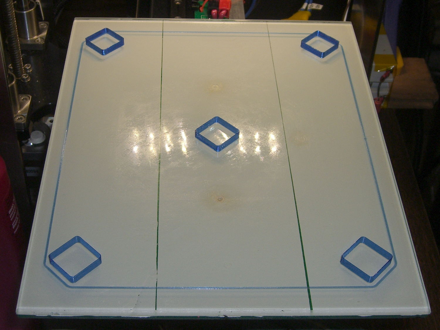
    Distribute five thinwall hollow boxes across the build platform:

    M2 V4 nozzle - thinwall boxes
    M2 V4 nozzle – thinwall boxes

    If the wall thickness (in the XY plane) doesn’t come out exactly right, fix that first by verifying the filament diameter setting, then adjusting the Extrusion Multiplier. If the extruder doesn’t produce the same wall thickness that the slicer calls for, you won’t get good results from anything else. In this case, they all have 0.40 mm thick walls, with 0.25 mm layers.

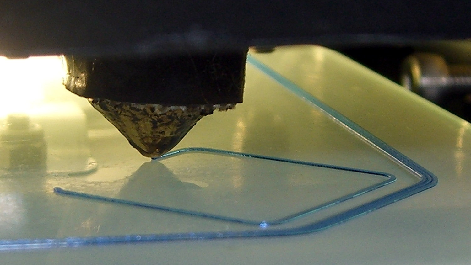
    The first layer of all five boxes should be identical:

    M2 V4 nozzle - thinwall box first layer
    M2 V4 nozzle – thinwall box first layer

    If the platform isn’t absolutely flat and properly aligned, those five first layers won’t be the same thickness. It’s surprisingly easy to spot differences under 0.05 mm, so pay attention to what’s happening.

    When they’re done, pop them off and measure their actual height. I measure across adjacent sides, leaving the corners / stray hairs / snot out of the measurement, and figure the eyeballometric average of the values, which usually differ by less than ±0.03 mm. Write the height on the side to eliminate future angst:

    Thinwall Box - platform height
    Thinwall Box – platform height

    The boxes should be 5.00 mm tall, so the leftmost box is short by -0.02 mm and the rightmost by -0.15 mm. The five boxes were 4.98, 4.95, 4.93, 4.92, and 4.85, with a mean of 4.93 mm. The variation across the 200×250 mm platform is 0.13 mm, which is pretty good.

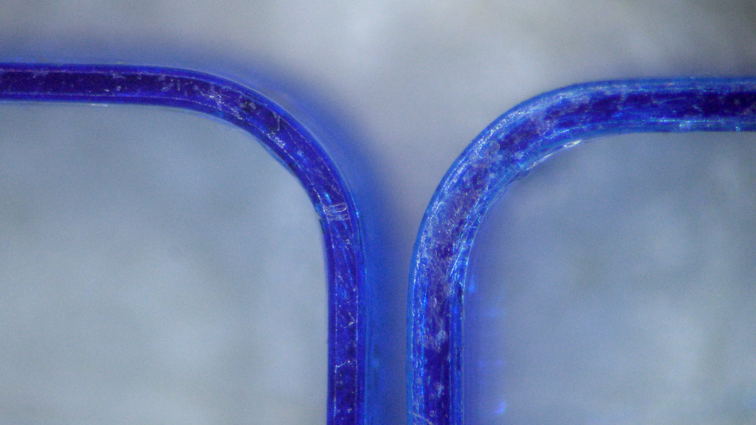
    Comparing the bottom layers of those boxes, the first layer of the 4.85 mm box is definitely squashed:

    Thinwall Hollow Boxes - first layer bottom view - 4.98 4.85 mm
    Thinwall Hollow Boxes – first layer bottom view – 4.98 4.85 mm

    Once you know what to look for, it’s also obvious from the side (4.98 on the left, 4.85 on the right, bottom layers facing each other):

    Thinwall boxes - 4.98 4.85 - bottom layers
    Thinwall boxes – 4.98 4.85 – bottom layers

    Keep in mind that’s a difference of 0.13 mm = 130 µm, just over the ±0.05 mm I usually bandy about. The nominal layers are 0.25 mm = 250 µm.

    A bit more magnification shows the nicely rounded first layer of the 4.98 mm box (rightmost thread of leftmost set):

    Thinwall Box - 4.98 mm
    Thinwall Box – 4.98 mm

    And the squashed first layer of the 4.85 mm box (likewise):

    Thinwall Box - 4.85 mm
    Thinwall Box – 4.85 mm

    Because the Z axis moves upward (on the M2, the platform moves downward) by exactly the layer thickness at the end of each layer, the first layer must absorb the entire difference between the desired thickness and the actual nozzle-to-platform distance. That squashed first layer is 0.10 mm thick, a bit less than half of the nominal 0.25 mm. The second layer of each box looks just like all the higher layers.

    Adjusting the first layer thickness by tweaking the initial Z-axis home position in the startup G-Code allows fine tuning without fussing with the mechanical settings. Having moved the Z-axis home switch to the middle of the X-axis gantry eliminates all those adjustments; tweaking the G-Code is the only way to go.

    You can set the Z-axis offset for a very slight squish, with the maximum nozzle-to-platform distance at 0.25 mm and the minimum set by the other end of the total misalignment, because the plastic won’t adhere to the platform when the nozzle-to-platform distance exceeds the nozzle diameter.

    Think of it this way: the plastic emerges from a 0.35 mm nozzle as a (slightly larger than) 0.35 mm cylinder that must squash to become a 0.25 mm high x 0.40 mm wide thread. Given the measurements above, setting the Z-axis home position to make the average box height equal to 5.00 mm would make the tallest box come out at 5.07 mm, which requires a 0.32 mm actual first layer that probably wouldn’t stick well at all.

    When your printer can consistently produce five thinwall boxes with the proper wall thickness and height, then you can move on to more complex objects.

    Selah.