Ed Nisley's Blog: Shop notes, electronics, firmware, machinery, 3D printing, laser cuttery, and curiosities. Contents: 100% human thinking, 0% AI slop.
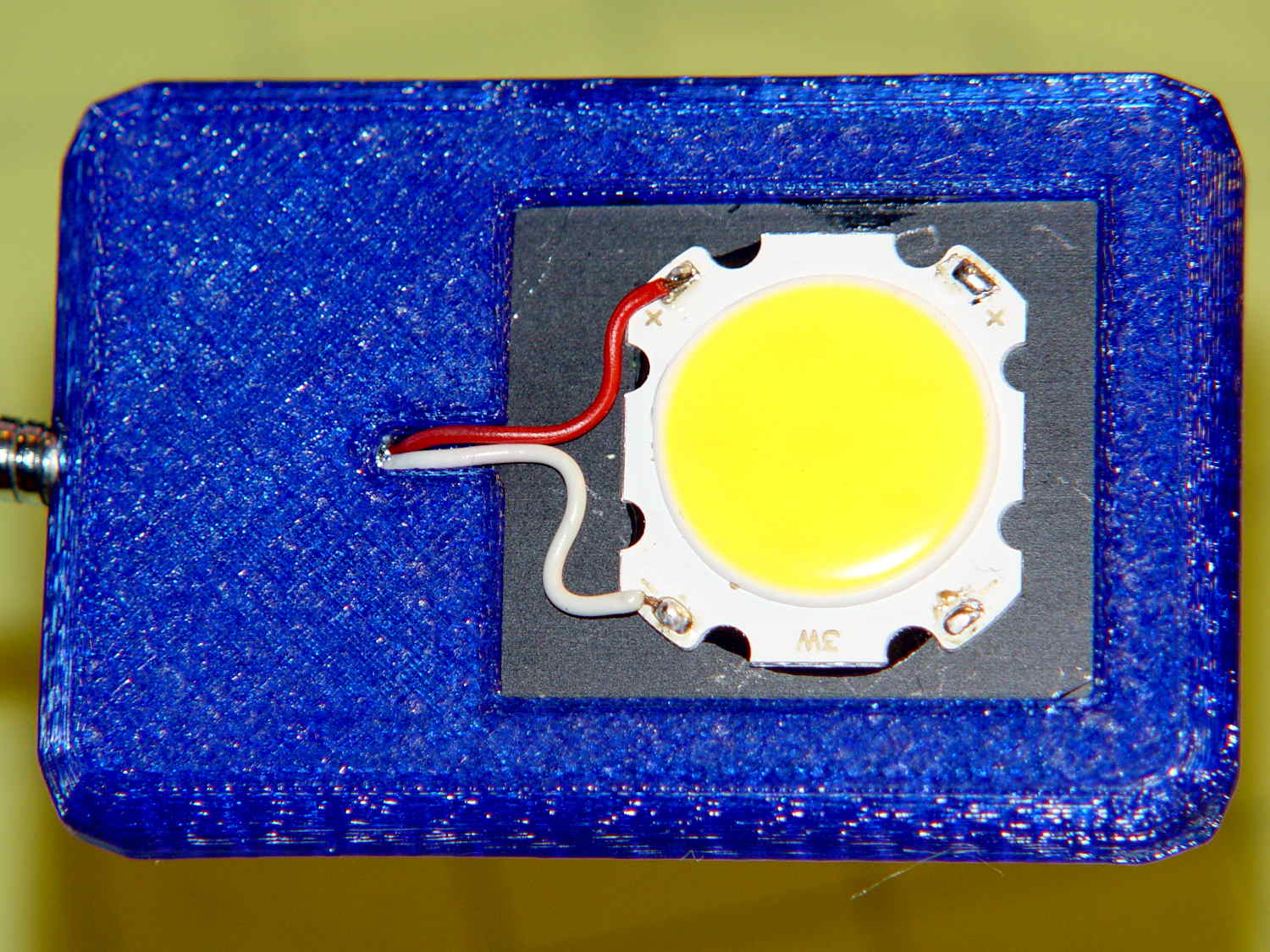
The LED’s aluminum baseplate (perhaps there’s an actual “board” inside the yellow silicone fill) is firmly epoxied to a small heatsink from the Big Box o’ Heatsinks, chosen on the basis of being the right size and not being too battered.
The rather limited specs say the LED supply voltage can range from 9 to 12 V, suggesting a bit of slack, with a maximum dissipation of 3 W, which definitely requires a heatsink.
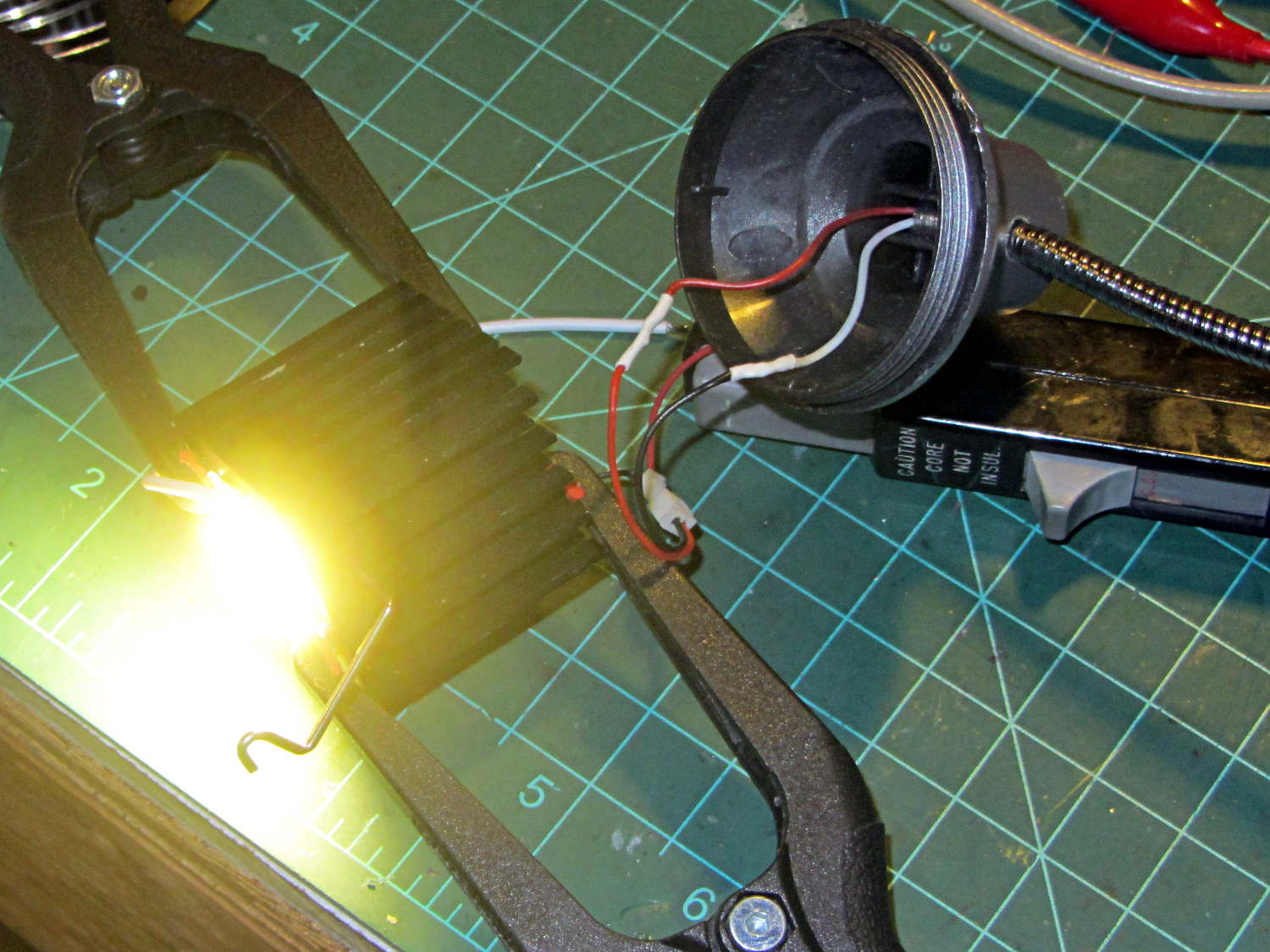
The First Light test looked promising:
COB LED Desk Lamp – first light
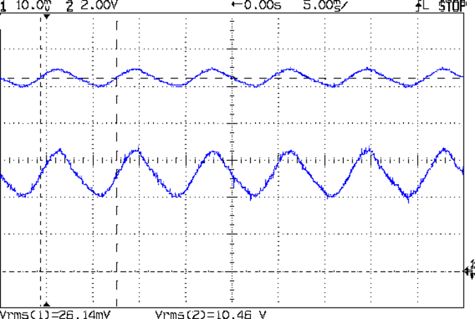
That’s driven from the same 12 VDC 200 mA wall wart that I used for the failed ring light version. Measuring the results shows that the supply now runs at the ragged edge of its current rating, with the output voltage around 10.5 V with plenty of ripple:
COB LED V I 100ma div
The 260 mA current (bottom, trace 1 at 100 mA/div) varies from 200 to 300 mA as the voltage (top, trace 2 at 2 V/div) varies between 10 V and a bit under 11 V. If you believe the RMS values, it’s dissipating 2.7 W and the heatsink runs at a pleasant 105 °F in an ordinary room. The wall wart gets about as warm as you’d expect; it contains an old heavy-iron transformer and rectifier, not a trendy switcher.
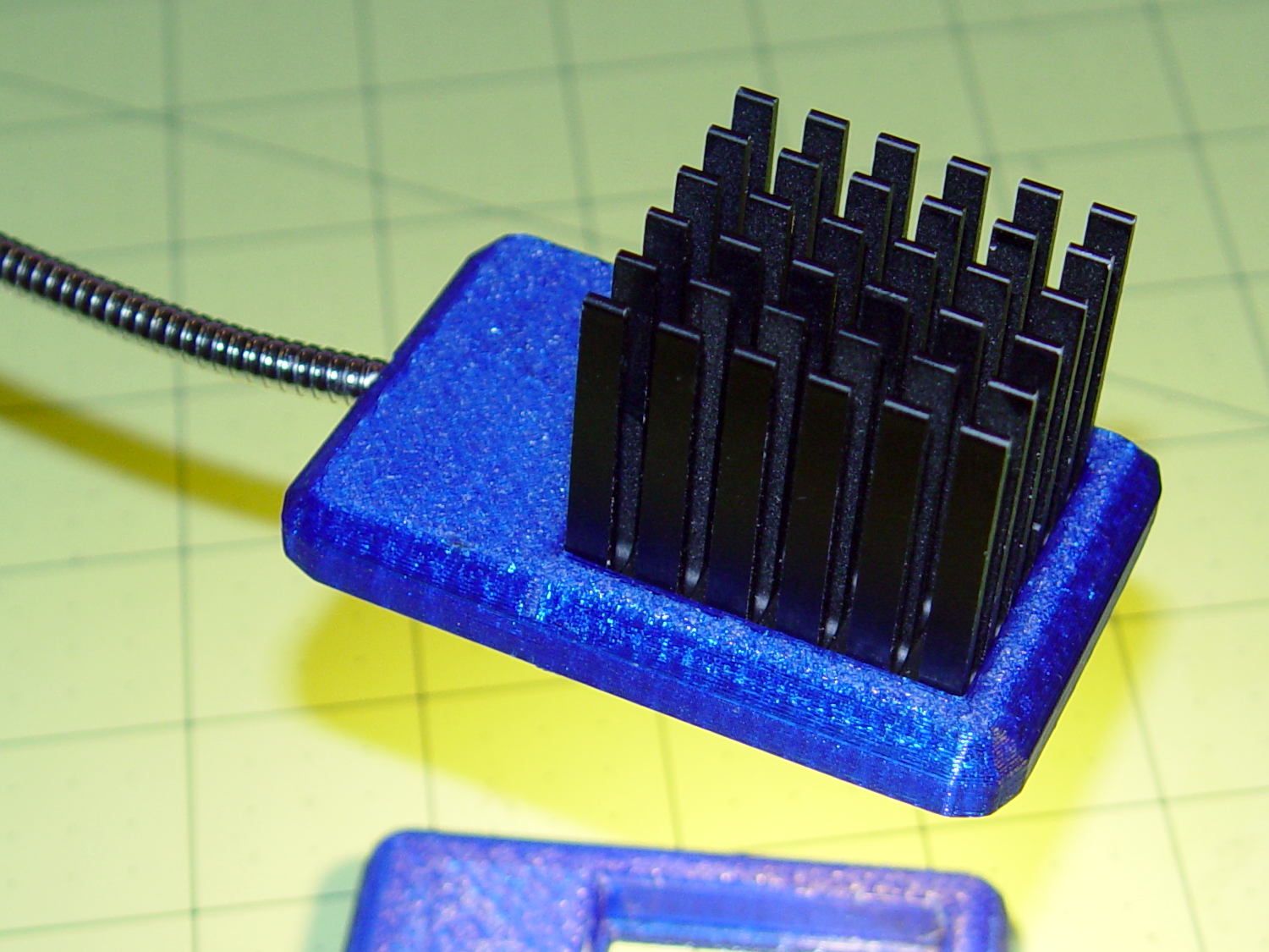
The heatsink mount looks nice, in a geeky way:
COB LED Desk Lamp – side detail
The left side must be that long to anchor the gooseneck; I thought about tapering the slab a bit, but, really, it’s OK the way it is. Dabs of epoxy hold the gooseneck and heatsink in place.
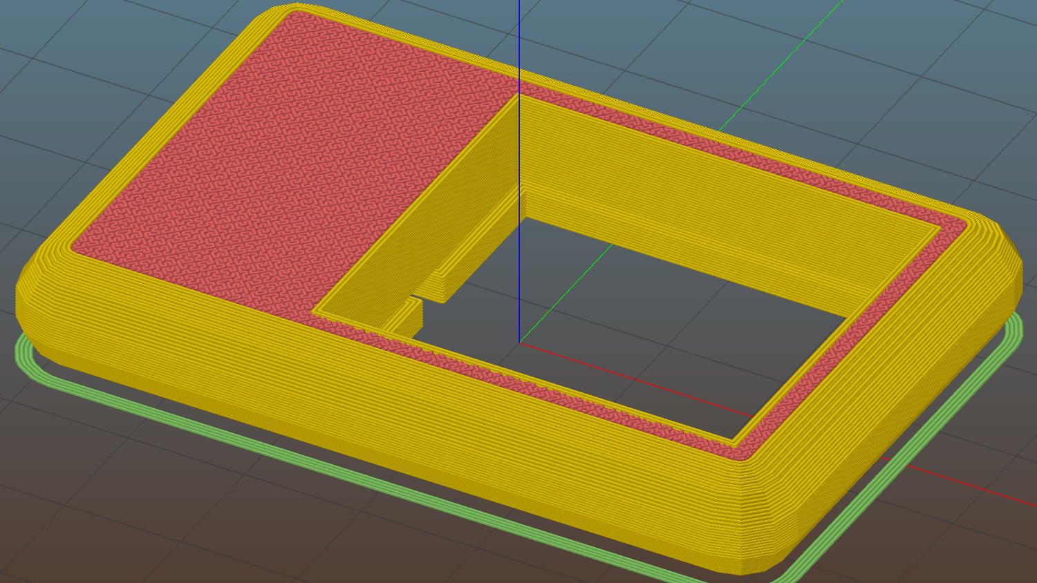
The heatsink rests on a small ledge at the bottom of the slab that’s as tall as the COB LED is thick, with a wire channel from the gooseneck socket:
COB LED Heatsink mount – Slic3r
The Hilbert Curve infill on the top produces a textured finish; I’m a sucker for that pattern.
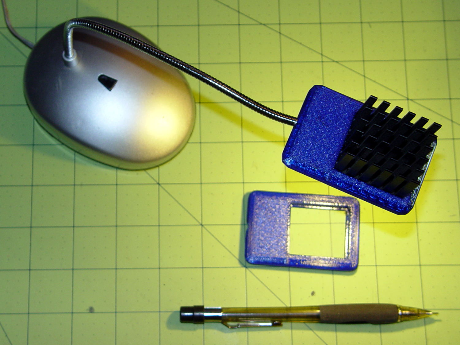
The old lamp base isn’t particularly stylin’, but the new head lights up my desk below the big monitors without any glare:
The tiny posts on the fencing helmet ear grommet produced a remarkable amount of PETG hair, because the nozzle had to skip between four separate pieces on the platform at each layer:
So I told Slic3r to build each part separately:
Fencing helmet grommet – separate builds – first attempt
Due to absolutely no forethought or planning on my part, that actually worked. Slic3r defines a cylindrical keep-out zone around the nozzle that I set to 15 mm radius and 25 mm height, but those numbers are completely wrong for the M2, particularly with a V4 hot end.
To the rear, the nuts & bolts along the bottom of the X gantry sit 5 mm above the V4 nozzle, with the relaxed actuator on my re-relocated Z-axis home switch at Z=+1 mm:
V4 PETG – extruder priming
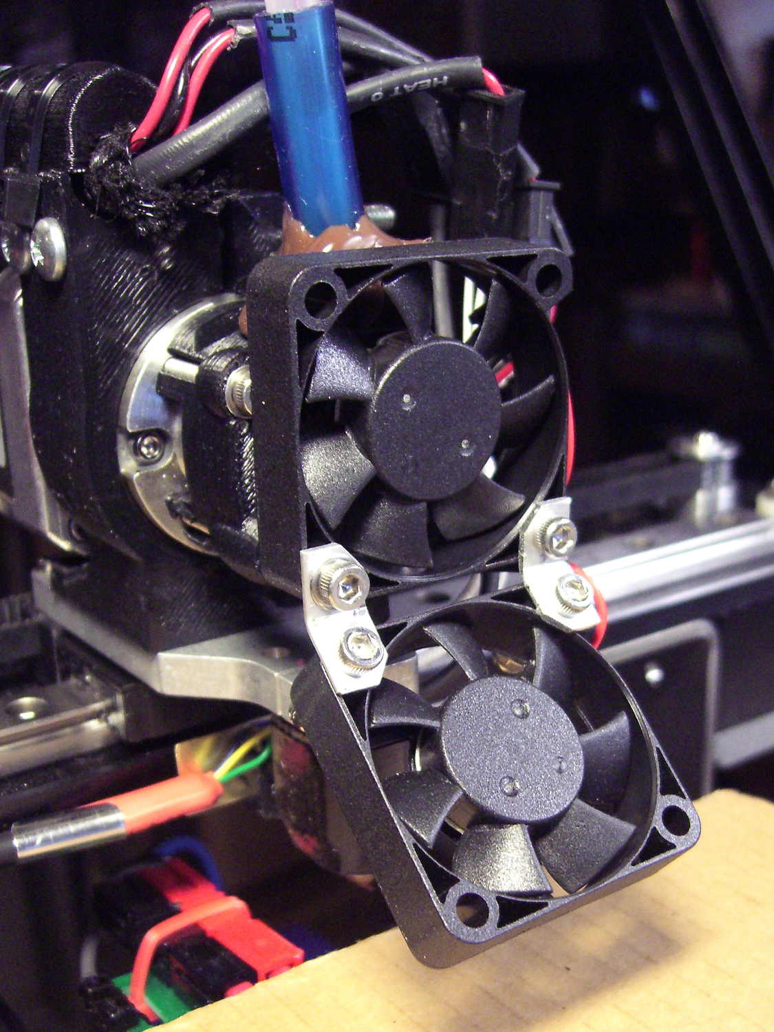
To the front, the bed fan doesn’t sit much higher:
M2 V4 Extruder – 24 V fans
As it turned out, the front washers built first, sitting there in front of the gantry and behind the fan, the rear washers appeared last, and Everything Just Worked.
However, even though the M2’s layout won’t allow for automated layout, I figured I could do it manually by building the parts from front to rear:
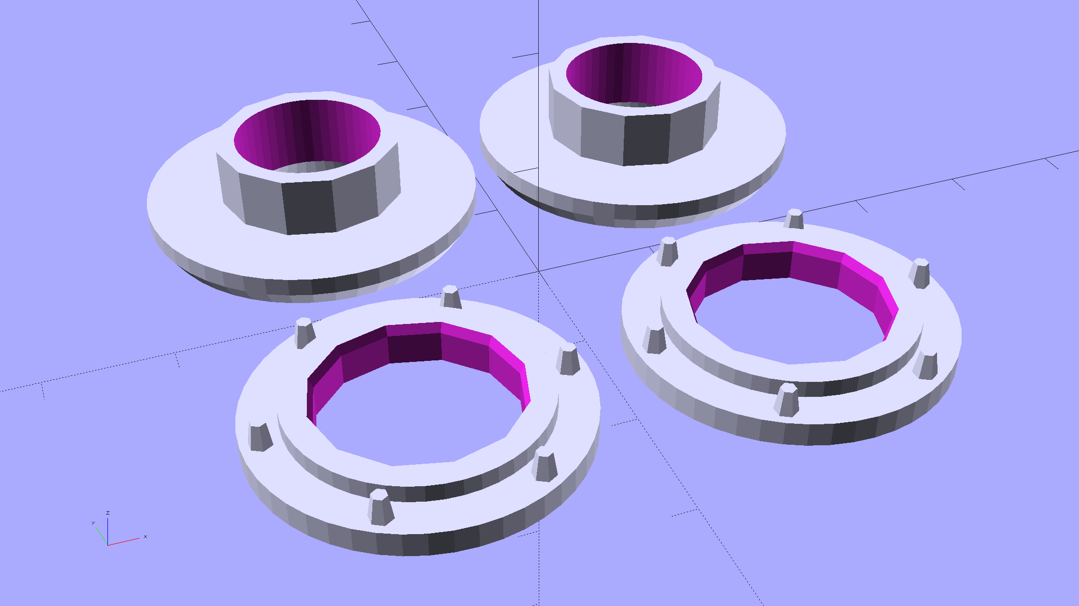
Fencing Helmet Ear Grommet – Slic3r layout
That way, the already-built parts never pass under the gantry / switch. For particularly tall parts, I could remove / relocate the bed fan to clear the already-built parts as they appear.
Come to find out that Slic3r, for whatever reason, doesn’t build the parts in the order you’d expect from the nice list on the far right side of the screen:
Sequential Build Order – Slic3r vs Pronterface
Worse, the Slic3r 3D preview shows the threads by layer (which is what you’d expect), rather than by object for sequential builds:
Slic3r – sequential preview vs build order
I don’t know how you’d force-fit a four-dimensional preview into the UI, so I won’t complain at all.
There’s no way to tell which part will build first; selecting the part will highlight its entry in the list (and vice versa), but the order of appearance in that list doesn’t tell you where the G-Code will appear in the output file. That’s not a problem for extruders with a keep-out volume that looks like a cylinder, so there’s no reason for Slic3r to do it any differently: it will manage the extruder position to clear all the objects in any order.
The Pronterface preview creates the objects by reading the G-Code file and displaying the threads in order, so, if you’re quick and it’s slow, you can watch the parts appear in their to-be-built order. The detailed preview (in the small window on the right in the screenshot) does show the parts in the order they will be built as you scroll upward through the “layers”, which is the only way you can tell what will happen.
So doing sequential builds requires iterating through these steps until the right answer appears:
Add all objects separately to get each one as a separate line in the list to the right
Using the More option to duplicate objects produces multiple objects per line = Bad Idea
Arrange objects in a line from front to back
Export G-Code file
Load G-Code file into Pronterface
Pop up the Pronterface layer preview, scroll upward to show build order, note carefully
Rearrange parts in Slic3r accordingly
That’s do-able (note the different order from the Slic3r preview):
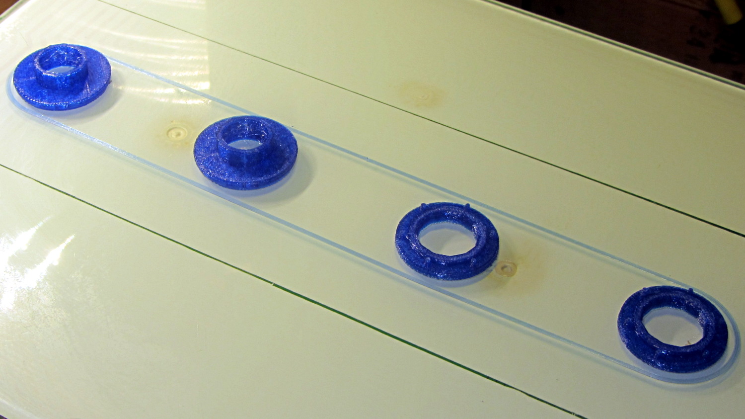
Fencing helmet grommet – manual sequential build
But it’s tedious and enough of a pain that it probably makes no sense for anything other than parts that you absolutely can’t build any other way.
In this case, completing each of the bottom washers separately eliminated all of the PETG hair between the small pegs. The upper washers still had some hair inside the inner cylinder, but not much. If you were fussy, you could suppress that by selecting “Avoid crossing perimeters”, at the cost of more flailing around in the XY plane.
All those spare grommets will make a good show-n-tell exhibit…
Our Larval Engineer practiced fencing for several years, learning the fundamental truth that you should always bring a gun to a knife fight:
Fencing – taking a hit
It’s time to pass the gear along to someone who can use it, but we discovered one of the ear grommets inside the helmet had broken:
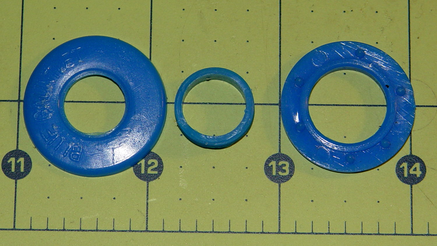
Blue Gauntlet M003-BG Helmet – broken ear grommet
The cylinder in the middle should be attached to the washer on the left, which goes inside the helmet padding. It’s a tight push fit inside the washer on the right, which goes on the outside of the padding. Ridges along the cylinder hold it in place.
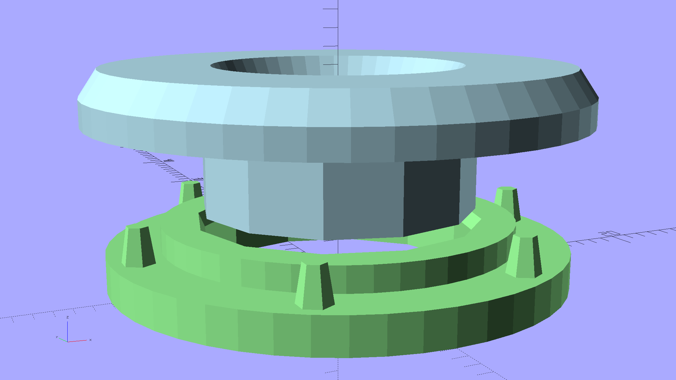
Being an injection-molded polyethylene part, no earthly adhesive or solvent will bother it, soooo… the solid model pretty much reproduces the original design:
Fencing Helmet Ear Grommet – show
The top washer goes inside the padding against your (well, her) ear, so I chamfered the edges sorta-kinda like the original.
There are no deliberate ridges on the central cylinder, but printing the parts in the obvious orientation with no additional clearance makes them a very snug push fit and the usual 3D printing ridges work perfectly; you could apply adhesive if you like. The outside washer has a slight chamfer to orient the post and get it moving along.
The posts keep the whole affair from rotating, but I’m not sure they’re really necessary.
Printing a pair doesn’t take much longer than just one:
Fencing Helmet Ear Grommet – build
It doesn’t look like much inside the helmet:
Blue Gauntlet M003-BG – replacement ear grommet – installed
Vacuum cleaner dust brushes, separated by millimeters and decades:
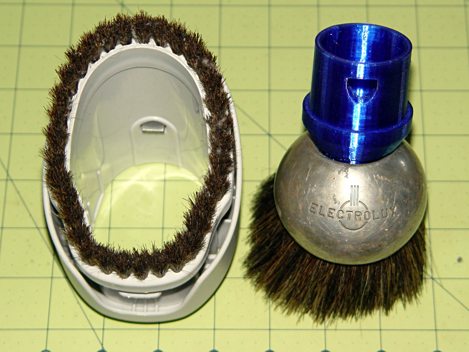
Kenmore vs adapted Electrolux dust brushes
The bulky one on the left came with our new Kenmore Progressive vacuum cleaner. It’s fine for dust on a flat horizontal or vertical surface and totally useless for dust on actual objects. It’s supposed to snap around the handle at the end of the cleaner’s flexy hose, where it helps make the entire assembly too large and too clumsy, or on the end of the “wand”, where it’s at the wrong angle. The bonus outer shell slides around the stubby bristles in the unlikely event they’re too long for the flat surface at hand.
The brush on the right emerged from the Box o’ Electrolux Parts that Came With The House™, must be half a century old, and consists of a cast aluminum lump with various holes milled into it, adorned with luxuriously long and flexible horsehair. Suffice it to say they don’t make ’em like that any more. Heck, they probably don’t make horses with hair like that any more, either.
The short snout fits neatly into the space available inside the ball. The abrupt ledge at the top of the snout, of course, didn’t work well; I rushed the design for a show-n-tell.
The OpenSCAD source code (as a Github gist) bevels that ledge and tweaks the interior air channel a bit:
That’s supposed to prevent the WordPress post editors from destroying the formatting…
So the dishwasher ate another rack protector, which happens a few times a year. I’m getting low on spares, so maybe it’s time to run off a few in cyan PETG to see if the cute support structure will still be removable:
Dishwasher rack protector – support model
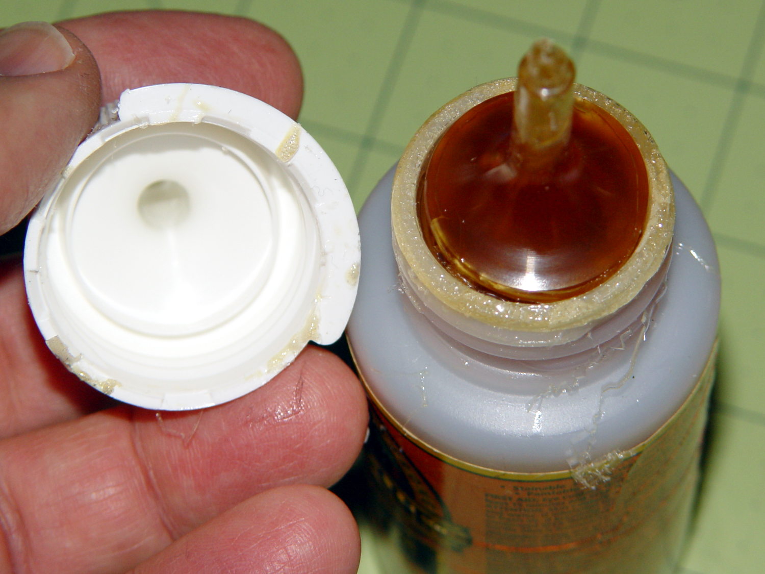
Anyhow, this time I used urethane glue, because the last of the acrylic caulk went into another project. I store the Gorilla Glue bottle upside-down so the entire top doesn’t cure solid, but:
Gorilla Glue – cured in bottle
Usually, it’s just cured in the snout. This time, the layer across the bottom was a few millimeters thick and the glue below seemed rather thick. I tossed the solid lump, slobbered a dab of thick goo on the dishwasher rack, jammed the new protector in place, replaced the cap, and declared victory.
That’s why I no longer buy that stuff in The Big Bottle…
The tab supporting the strut with the center slides for the lower drawers in our Whirlpool refrigerator broke of its own accord. This is a problem of long standing, somewhat exacerbated by the fact that lifting the strut will break the tab without much effort at all, but this time the drawers pulled the strut downward hard enough to not only break the tab, but also tear the small tabs that align the bracket right out of the frame.
While pondering the problem, I glued the broken chunk back into the frame:
Refrigerator Drawer Strut – clamping front plate
We agreed that, after nigh onto two decades, it would be OK to swap the position of the two drawers, so as to let the strut use the undamaged part of the frame seen below. Presumably, we’ll eventually get used to having the apples on the right and the veggies on the left.
But it was obvious Something Serious Had To Be Done about the tab.
The tab should align like this inside the frame:
Refrigerator Drawer Strut Tab – alignment
The rightmost part of the tab rests atop a U-shaped metal bar that also supports and stiffens the entire front of the frame, but cantilevering the weight of both drawers on that extended tab overpowered my last attempt at making a glue joint. Soooo, I decided to build a (wait for it …) 3D printed part that screws firmly to the front of the strut.
The first step involved introducing the strut to Mr Belt Sander to strip the wreckage of the OEM tab from the front end (visible through the opening) and smooth things out, then measuring the remainder. The locating flange inside the frame almost defeated me, but eventually I found a tool that fit inside the strut opening and around the flange:
Refrigerator Drawer – measuring flange
Which produced a sketch of the key dimensions:
Refrigerator Drawer Strut – Dimension Doodles
Which became an extruded polygon with a few holes punched in the side:
Refrigerator Shelf Strut Tab – solid model
Building it standing up wraps the plastic threads around the entire tab and stacks the layers along the length of the tab. Doing it lying down in the obvious hump-up orientation would put the layers parallel to the bottom surface, where they can pull apart under load.
The key innovation here involves being willing to assemble the tab to the strut in situ, without insisting it fit through the frame opening and be more-or-less easily removable. That let me bulk up the tab to match the end of the strut, fill the entire frame opening with plastic, and get enough bulk for a pair of 4-40 screws that, being loaded in shear, should withstand the weight of all those fruits & veggies in the drawers.
The screws simply thread into the holes in the tab, without benefit of tapping. The OpenSCAD code now includes a pair of nut traps, but I’m hoping they won’t be needed.
The new tab really does fill the space available:
Refrigerator Drawer Strut – new tab in place
The OpenSCAD code now moves the notch half a millimeter further away from the strut to center it over the ridge. What’s not obvious is how the frame slants toward the tab over the U-bar: the tab just barely clears and probably should have a tapered nose. You may add that if you like.
The U-shaped bar constrains the tab pretty firmly and supports the end, which should now be plump enough to withstand the forces involved. The screws sit horizontally with the frame installed and can’t pull out, which is why I think they can get along without nut traps.
It’s built in cyan PETG with three perimeter threads and 40% 3D Honeycomb fill, making it essentially a solid block of plastic; it’ll be interesting to see what fails next.
The OpenSCAD source code, which I hammered out in a white-hot fury:
// Refrigerator Shelf Strut Tab
// Ed Nisley KE4ZNU December 2015
//- Extrusion parameters must match reality!
ThreadThick = 0.25;
ThreadWidth = 0.40;
HoleWindage = 0.2;
Protrusion = 0.1; // make holes end cleanly
inch = 25.4;
function IntegerMultiple(Size,Unit) = Unit * ceil(Size / Unit);
//----------------------
// Dimensions
TabSize = [20.0,12.0,35.0]; // length from bracket, height, width along front
SlotSize = [3.0,7.0];
SlotX = 7.0;
TabProfile = [
[0,0],
[12,0], [12,7.0],
[TabSize[0],7.0], [TabSize[0],TabSize[1]],
[SlotX + SlotSize[0]/2,TabSize[1]],
[SlotX + SlotSize[0]/2,5.0], [SlotX - SlotSize[0]/2,5.0],
[SlotX - SlotSize[0]/2,TabSize[1]],
[0,TabSize[1]]
];
ScrewY = 7.0;
ScrewOC = 25.0;
ScrewOD = 2.5;
NutOD = 6.6; // across flats
NutThick = 2.5;
//----------------------
// Useful routines
module PolyCyl(Dia,Height,ForceSides=0) { // based on nophead's polyholes
Sides = (ForceSides != 0) ? ForceSides : (ceil(Dia) + 2);
FixDia = Dia / cos(180/Sides);
cylinder(r=(FixDia + HoleWindage)/2,
h=Height,
$fn=Sides);
}
//----------------------
// Build it
difference() {
linear_extrude(height=TabSize[2],convexity=4)
polygon(points=TabProfile);
for (i=[-1,1]) {
translate([-Protrusion,ScrewY,i*ScrewOC/2 + TabSize[2]/2])
rotate([0,90,0])
rotate(180/6)
PolyCyl(ScrewOD,SlotX,6);
translate([SlotX - SlotSize[0]/2 - NutThick - Protrusion,ScrewY,i*ScrewOC/2 + TabSize[2]/2])
rotate([0,90,0])
rotate(180/6)
PolyCyl(NutOD,NutThick + SlotSize[0],6);
}
}
Maybe that’ll last until we finally scrap out the refrigerator…
Mary started doing “ruler quilting” that involves sewing seams aligned with templates, only to find that the thumbscrew holding the (modified) presser foot obscures the view to the left of the needle:
Kenmore Model 158 – OEM Presser Foot Screw
The screw looked to be 6-32 and I wanted to use a socket head cap screw, but thread turns out to be 6-40. Having previously bought the Brownell’s Fillister Head Screw Assortment specifically to solve that problem, all I had to do was cut the screw to length:
Kenmore Model 158 – Small Presser Foot Screw
The washer epoxied to the screw provides a bit more bearing surface.
Rather than putz with a screwdriver, this handle locates itself around the screw head; turn until the blade clicks into the screw slot, then tighten or loosen as needed:
Kenmore Model 158 – Presser Foot – Driver and Screw
The slot holds a chunk of spring steel (barely visible in the driver’s snout in group photo above) that accounts for the fat shaft around the screw head:
Presser Foot Screw Driver – top – Slic3r
I think the shaft could be a few millimeters narrower, but a bit of meat around the ends of the blade will support it against the torque.
The screw head slot is about 1 mm and the blade is 0.75 mm. I chopped the blade to fit by whacking the spring with a poorly tempered cold chisel, then flexing across the impact line until it broke. That chisel needed sharpening anyhow.
A dab of epoxy along the slot edges holds the blade in place. I inserted it flush with the top of the socket, then lined up the screw and pushed, with the steel bottomed out in the screw head and riding down for a perfect fit.
Then it’s all good!
The OpenSCAD source code:
// Presser Foot Screw Driver for Kenmore Model 158
// Ed Nisley - KE4ZNU - December 2015
use <knurledFinishLib_v2.scad>
//- Extrusion parameters must match reality!
// Print with 2 shells and 3 solid layers
ThreadThick = 0.20;
ThreadWidth = 0.40;
HoleWindage = 0.3; // extra clearance to improve hex socket fit
Protrusion = 0.1; // make holes end cleanly
inch = 25.4;
//----------------------
// Dimensions
SocketDia = 5.75; // generous fit on 6-40 fillister screw head
SocketDepth = 3.2;
Blade = [9.0,1.0,ceil(SocketDepth + 5)]; // inserted metal driver blade
echo(str("Blade: ",Blade));
ShaftDia = 1.5*Blade[0]; // un-knurled section diameter
ShaftLength = 10.0; // ... length
KnurlLen = 10.0; // length of knurled section
KnurlDia = 18.0; // ... diameter at midline of knurl diamonds
KnurlDPNom = 30; // Nominal diametral pitch = (# diamonds) / (OD inches)
DiamondDepth = 1.0; // ... depth of diamonds
DiamondAspect = 2; // length to width ratio
KnurlID = KnurlDia - DiamondDepth; // dia at bottom of knurl
NumDiamonds = ceil(KnurlDPNom * KnurlID / inch);
echo(str("Num diamonds: ",NumDiamonds));
NumSides = 4*NumDiamonds; // 4 facets per diamond
KnurlDP = NumDiamonds / (KnurlID / inch); // actual DP
echo(str("DP Nom: ",KnurlDPNom," actual: ",KnurlDP));
DiamondWidth = (KnurlID * PI) / NumDiamonds;
DiamondLenNom = DiamondAspect * DiamondWidth; // nominal diamond length
DiamondLength = KnurlLen / round(KnurlLen/DiamondLenNom); // ... actual
TaperLength = 0.50*DiamondLength;
KnobOAL = 2*TaperLength + KnurlLen + ShaftLength;
//----------------------
// Useful routines
module PolyCyl(Dia,Height,ForceSides=0) { // based on nophead's polyholes
Sides = (ForceSides != 0) ? ForceSides : (ceil(Dia) + 2);
FixDia = Dia / cos(180/Sides);
cylinder(r=(FixDia + HoleWindage)/2,
h=Height,
$fn=Sides);
}
module ShowPegGrid(Space = 10.0,Size = 1.0) {
Range = floor(50 / Space);
for (x=[-Range:Range])
for (y=[-Range:Range])
translate([x*Space,y*Space,Size/2])
%cube(Size,center=true);
}
//- Build it
ShowPegGrid();
difference() {
union() {
render(convexity=10)
translate([0,0,TaperLength]) // knurled cylinder
knurl(k_cyl_hg=KnurlLen,
k_cyl_od=KnurlDia,
knurl_wd=DiamondWidth,
knurl_hg=DiamondLength,
knurl_dp=DiamondDepth,
e_smooth=DiamondLength/2);
color("Orange") // lower tapered cap
cylinder(r1=ShaftDia/2,
r2=(KnurlDia - DiamondDepth)/2,
h=(TaperLength + Protrusion),
$fn=NumSides);
color("Orange") // upper tapered cap
translate([0,0,(TaperLength + KnurlLen - Protrusion)])
cylinder(r2=ShaftDia/2,
r1=(KnurlDia - DiamondDepth)/2,
h=(TaperLength + Protrusion),
$fn=NumSides);
color("Moccasin") // cylindrical extension
translate([0,0,(2*TaperLength + KnurlLen - Protrusion)])
cylinder(r=ShaftDia/2,h=(ShaftLength + Protrusion),$fn=NumSides);
}
translate([0,0,(KnobOAL - SocketDepth + Protrusion)])
PolyCyl(SocketDia,(SocketDepth + Protrusion),8); // screw head socket
translate([0,0,KnobOAL - (Blade[2] - Protrusion)/2])
cube(Blade + [0,0,Protrusion],center=true);
}