The Smell of Molten Projects in the Morning

Ed Nisley's Blog: Shop notes, electronics, firmware, machinery, 3D printing, laser cuttery, and curiosities. Contents: 100% human thinking, 0% AI slop.

Tag: M2

Using and tweaking a Makergear M2 3D printer

  • Tecumseh 36638 Throttle Knob

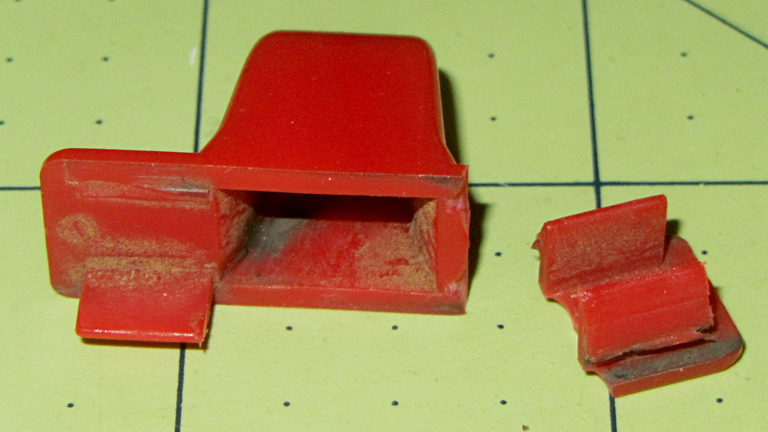
    The upper-left tab broke off this “knob” shortly after we got the leaf shredder:
    Throttle knob - broken original
    Throttle knob – broken original

    But it worked well enough that, following my usual course of action, I could ignore the problem. Until a few days ago, that is, when the remaining tab on that end pulled out of the slot on the engine and the whole affair bent into uselessness.

    It’s a $10 item from eBay (with free shipping), $8 from Amazon ($4, not eligible for Prime, so plus $4 shipping), out of stock at my usual online small engine source, and not worth biking a few dozen miles here & there to see if anybody has one. I know better than to look for repair parts at Lowe’s / Home Depot. It’s Tecumseh Part 36638, which may come in handy some day.

    So, we begin…

    It’s one of those pesky injection-molded miracle plastic doodads that can’t be printed in one piece, so I designed the tabs as separate parts and glued them in place. The solid model shows the intended assembly, with a bit of clearance around the tabs for tolerance and glue slop:

    Tecumseh Throttle Knob - solid model - show view
    Tecumseh Throttle Knob – solid model – show view

    External clearances aren’t an issue, so I made the base plate longer, wider, and thicker, which gave the tabs something to grab onto. The half-round knob is bigger, more angular, and uglier than the OEM knob, because I had trouble holding onto the original while wearing work gloves.

    Printing a few extra tabs allows the inevitable finger fumble:

    Throttle knob - on platform
    Throttle knob – on platform

    The tabs stand on edge to properly orient the printed threads around the perimeter: a great force will try to rip that triangular feature right off the tab, so wrapping the thread as shown maximizes the strength. Laying them flat on their backs would put the force in shear, exactly parallel to thread-to-thread bonds; I wouldn’t bet on the strength of those layers.

    The brim provides enough platform footprint around the tabs to keep them upright, but obviously isn’t needed around the knob. Although you could wrap a modifier mesh around one or the other, trimming the brim off the knob with a precision scissors seemed more straightforward.

    Slobbering generous drops of of IPS #4 solvent adhesive into the slots and over the tabs softened the PETG enough that I could ram the tabs into place, using a big pliers to overcome their feeble resistance:

    Throttle knob - glued latches
    Throttle knob – glued latches

    With the plastic still dazed from the fumes, I force-fit the knob into the slot on the engine:
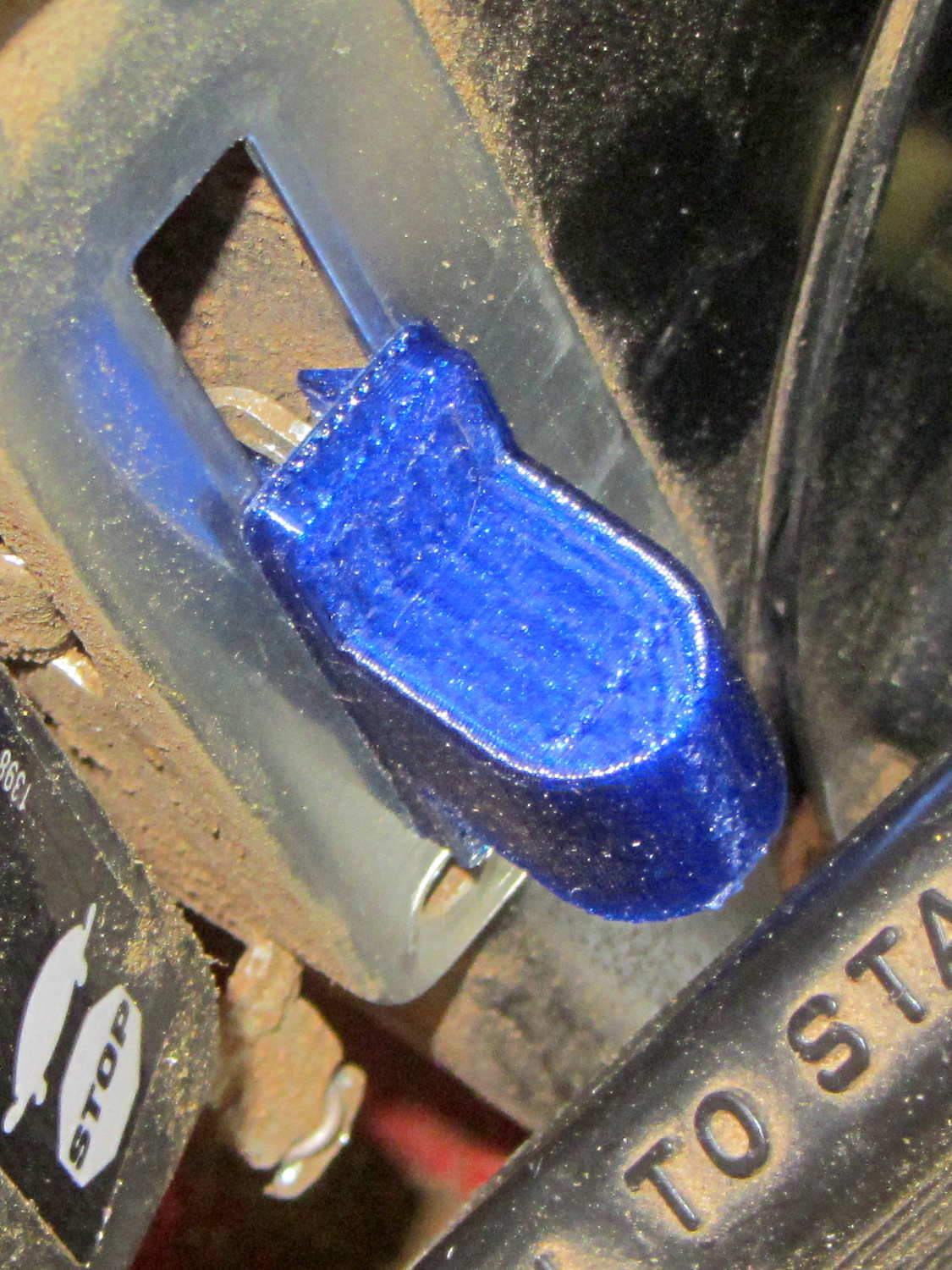
    Throttle knob - installed
    Throttle knob – installed

    The tabs eased back into position and seem to be holding the knob in place. Worst case: make a new knob, butter up the tabs with slow epoxy, ram knob into slot, then poke a screwdriver inside to realign the tabs against the slot edges.

    The solvent had a few cloudy days to evaporate before the next shredding session, whereupon the throttle once again worked exactly the way it should.

    The OpenSCAD source code:

    // Tecumseh 36638 Throttle Knob
    // Ed Nisley KE4ZNU November 2015
    
    Layout = "Build";					// Build Show Tab Base
    
    //- Extrusion parameters must match reality!
    
    ThreadThick = 0.25;
    ThreadWidth = 0.40;
    
    HoleWindage = 0.2;
    
    Protrusion = 0.1;			// make holes end cleanly
    
    inch = 25.4;
    
    function IntegerMultiple(Size,Unit) = Unit * ceil(Size / Unit);
    
    //----------------------
    // Dimensions
    
    BaseSize = [40,14,3.0];							// overall base plate outside engine controller slot
    
    Knob = [18,BaseSize[1],17];
    
    TabSize = [7.5,1.6,6.0];						// ovarall length, minimum width, overall height
    TabSocket = [8.0,2.0,BaseSize[2] - 2*ThreadThick];				// recess in base plate for tab 
    
    TabOuterSpace = 30.0;							// end-to-end length over tabs - sets travel distance
    SlotWidth = 7.75;								// engine controller slot width
    SlotThick = 1.5;								// engine controller slot thickness
    
    TabShape = [
    	[0,0],
    	[BaseSize[2] + TabSize[2],0],
    	[BaseSize[2] + TabSize[2],ThreadWidth],
    	[BaseSize[2] + SlotThick,2*TabSize[1]],
    	[BaseSize[2] + SlotThick,TabSize[1]],
    	[0,TabSize[1]]
    ];
    
    CapBaseOpening = [11,7.5,15];			// opening in base plate, Z = clearance from controller plate
    
    //----------------------
    // Useful routines
    
    module PolyCyl(Dia,Height,ForceSides=0) {			// based on nophead's polyholes
    
      Sides = (ForceSides != 0) ? ForceSides : (ceil(Dia) + 2);
    
      FixDia = Dia / cos(180/Sides);
    
      cylinder(r=(FixDia + HoleWindage)/2,
    		h=Height,
    	$fn=Sides);
    }
    
    //----------------------
    // Pieces
    
    module Tab() {
    	
    	linear_extrude(height=TabSize[0]) {
    		polygon(points=TabShape);
    	}
    }
    
    
    module Base() {
    	
    	CornerRad = BaseSize[1]/8;
    
    	difference() {
    		union() {
    			linear_extrude(height=BaseSize[2])
    				hull()
    					for (i=[-1,1], j=[-1,1]) 
    						translate([i*(BaseSize[0]/2- CornerRad),j*(BaseSize[1]/2 - CornerRad)])
    							circle(r=CornerRad,$fn=4*4);
    			translate([Knob[0]/2,0,BaseSize[2] - Protrusion])
    				rotate([0,-90,0])
    					linear_extrude(height=Knob[0])
    						hull() {
    							translate([Knob[2] - Knob[1]/2,0])
    								circle(d=Knob[1],$fn=8*4);
    							translate([0,-Knob[1]/2,0])
    								square([Protrusion,Knob[1]]);
    						}
    		}
    		
    		translate([-CapBaseOpening[0]/2,-CapBaseOpening[1]/2,-Protrusion])
    			cube(CapBaseOpening + [0,0,-CapBaseOpening[1]/2 + Protrusion],center=false);
    			
    		translate([0,0,CapBaseOpening[2] - CapBaseOpening[1]/2])
    			rotate([0,90,0]) rotate(180/8)
    				cylinder(d=CapBaseOpening[1]/cos(180/8),h=CapBaseOpening[0],center=true,$fn=8);
    				
    		for (i=[-1,1], j=[-1,1])
    			translate([i*(TabOuterSpace/2 - TabSocket[0]/2),j*(SlotWidth/2 - TabSocket[1]/2),TabSocket[2]/2 - Protrusion])
    				cube(TabSocket + [0,0,Protrusion],center=true);
    	}
    }
    
    
    //----------------------
    // Build it
    
    if (Layout == "Base")
    	Base();
    	
    if (Layout == "Tab")
    	Tab();
    	
    if (Layout == "Show") {
    	Base();
    	
    		for (i=[-1,1], j=[-1,1])
    			translate([i*(TabOuterSpace/2 - TabSocket[0]/2),j*(SlotWidth/2 - TabSocket[1]/2),0])
    				translate([j < 0 ? TabSize[0]/2 : -TabSize[0]/2,j < 0 ? TabSize[1]/2 : -TabSize[1]/2,BaseSize[2] - 2*ThreadThick])
    					rotate([0,90,j < 0 ? -180 : 0])
    					Tab();
    }
    
    if (Layout == "Build") {
    	Base();
    	
    	for (i=[0:5])					// build a few spares
    		translate([-7*TabSocket[1] + i*3*TabSocket[1],BaseSize[1],0])
    			rotate(90)
    				Tab();
    }
    

    The original doodle showing the OEM knob dimensions and some failed attempts at fancy features:

    Tecumseh Throttle Knob - doodles
    Tecumseh Throttle Knob – doodles
  • Tiny Cylinder Test Object

    A discussion on the M2 forums prompted this test object:

    Tiny Cylinder - 0.9x9.0 mm
    Tiny Cylinder – 0.9×9.0 mm

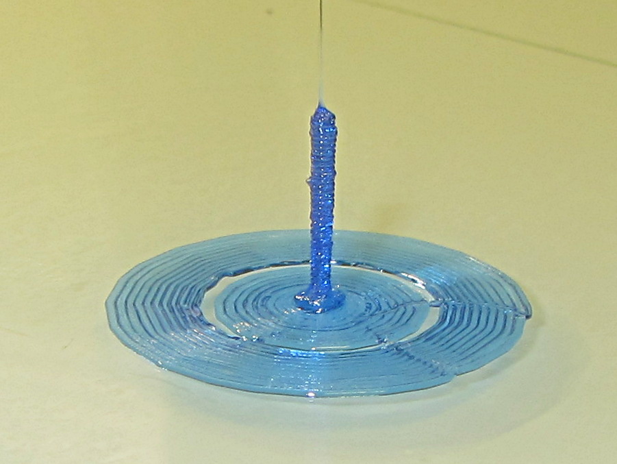
    Sliced with Slic3r for PETG at 1 mm/s, with fans in full effect. It sits amid a 5 mm brim, inside a skirt that uses 15 mm of filament, giving it a Washington Monument aspect.

    The challenge was to print a 0.7x9.0 cylinder, which doesn’t work well with a 0.35 mm nozzle. Instead, I went with 0.9 mm diameter. The result measures 1.1 mm over all the obvious bumps, so it’s surprisingly close. The “nail head” at the bottom most likely comes from the hot end depressurizing as it suddenly transitions from 15 mm/s in the brim to 1 mm/s for the cylinder.

    Fairly obviously, you can’t print something like that at full speed (50 mm/s was claimed for a Rep 2 and I don’t believe that for an instant). Indeed, it’s such a pathological model that Slic3r’s minimum layer time and small perimeter settings had no effect; I had to manually set the extrusion speed to 1 mm/s in order to make it work. Plus adding that brim, because I knew it wouldn’t stand by itself.

    Other than that, printing it was no big deal.

    A picture from that M2 forum discussion suggests you can go crazy with this stuff:

    20 mm, 40 mm, 60 mm and 120 mm
    20 mm, 40 mm, 60 mm and 120 mm

    The OpenSCAD source code for my version:

    cylinder(d=0.9,h=9,$fn=8);
    

    There, now, that wasn’t so hard, was it?

  • Monthly Science: Dehumidification by Rice

    As part of a discussion on the M2 forums about using rice to dehumidify 3D printer filament, I replaced the 500 g bag of silica gel in the basement safe with a bowl containing 200 g of long-grain brown rice from our rice supply and let it sit for a while:

    Basement Safe Humidity - Rice vs. Silica Gel - 2015-10-31
    Basement Safe Humidity – Rice vs. Silica Gel – 2015-10-31

    The abrupt drop in humidity from 52% to the logger’s minimum 15% marks the point where I replaced the rice with a fresh bag of silica gel, with a door opening shortly thereafter. The basement air outside the safe varied between 52% and 54% during that time, so the air inside the safe trended upward toward that goal.

    The rice still weighed exactly 200 g after its stay in the safe, so we can conclude it hadn’t absorbed or released any water.

    Conclusion: nope, rice doesn’t work as a dehumidifier…

  • LED Ring Desk Lamp

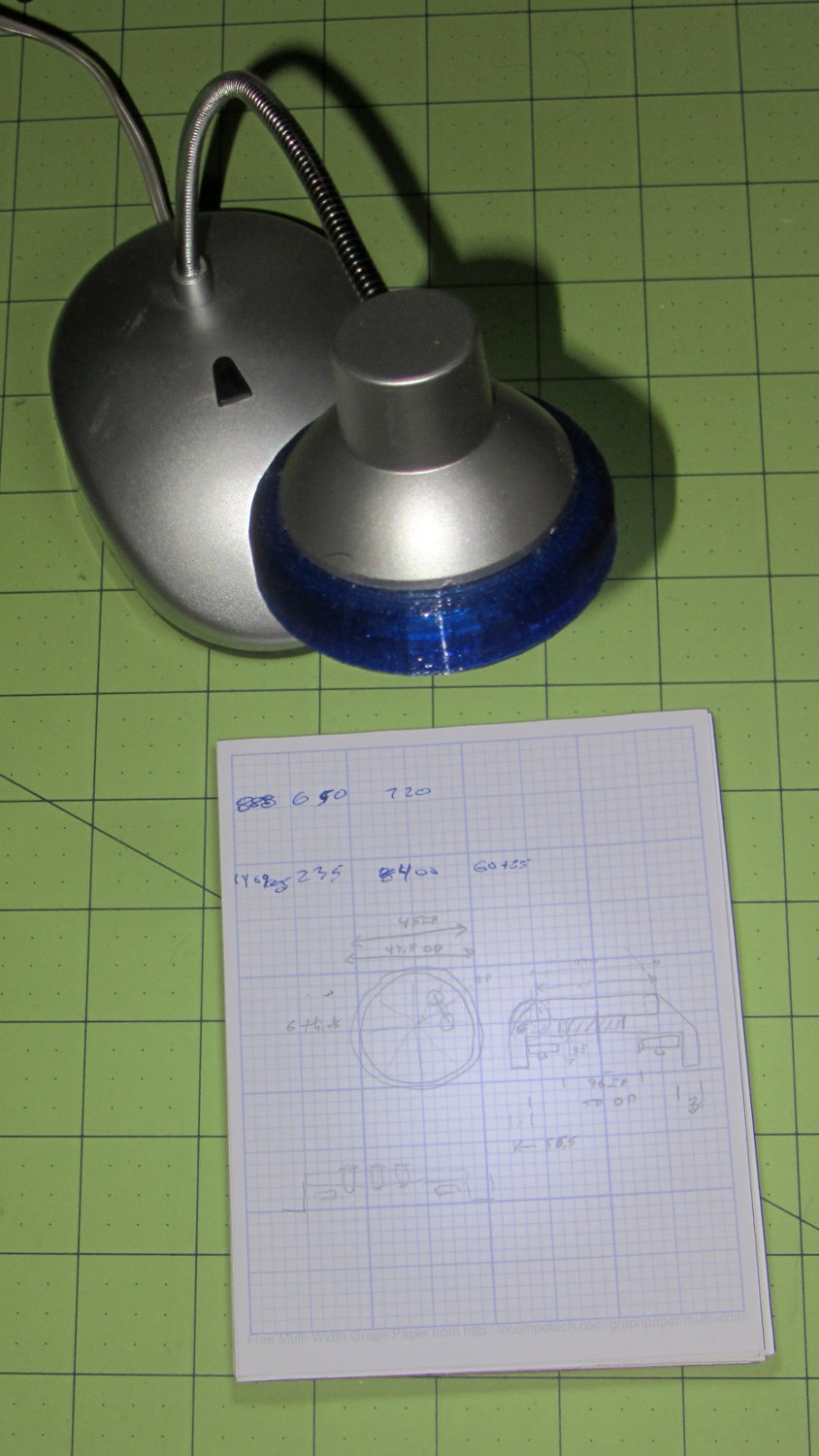
    A defunct desk lamp emerged from the clutter and cried out for bright, new LEDs. This adapter puts a small LED ring and nine white LEDs on the original lamp head:

    Ring Light Mount - in operation
    Ring Light Mount – in operation

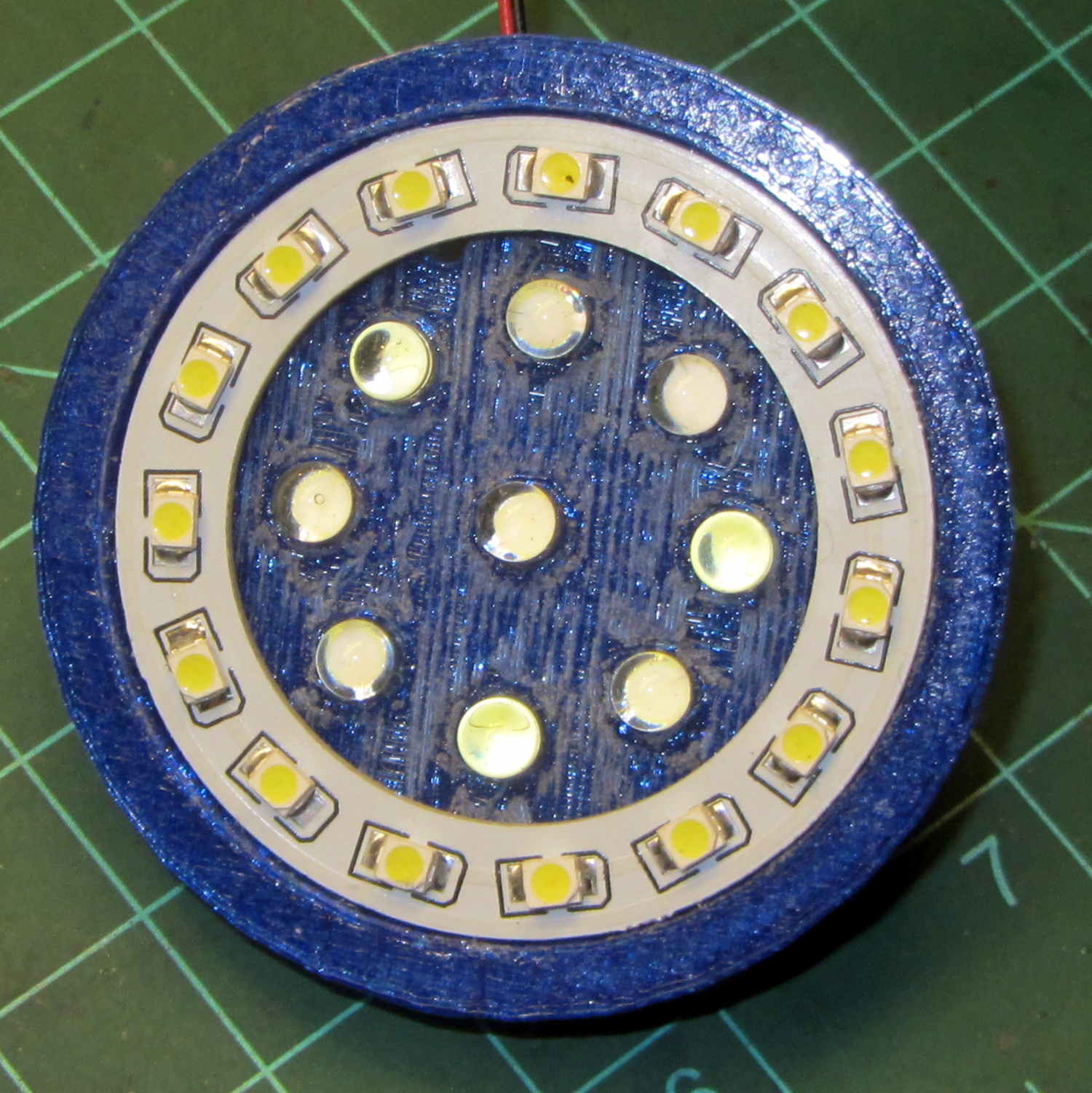
    Peering into the business end, before mounting it on the lamp, shows some abrasive adjustment on the inside layer:

    Ring Light Mount - LEDs installed
    Ring Light Mount – LEDs installed

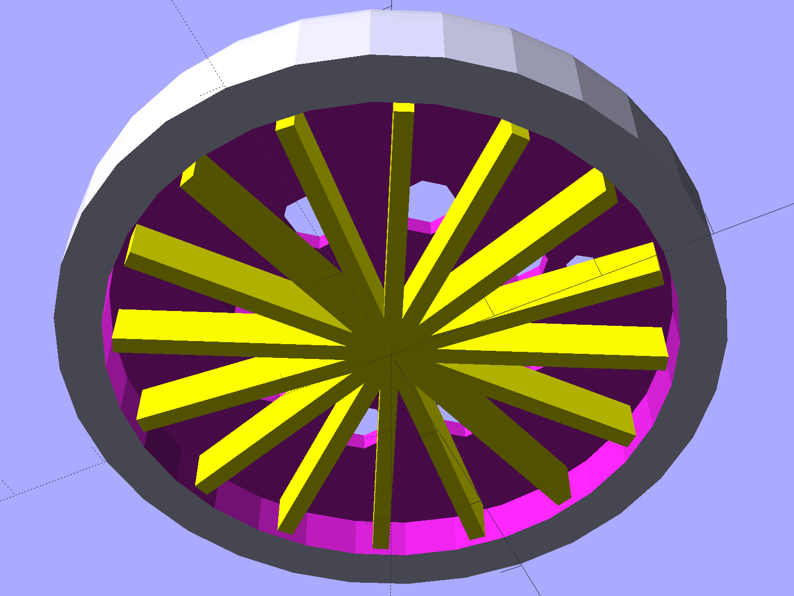
    That layer printed over a quick-and-easy support spider:

    Ring Light Mount - solid model - bottom
    Ring Light Mount – solid model – bottom

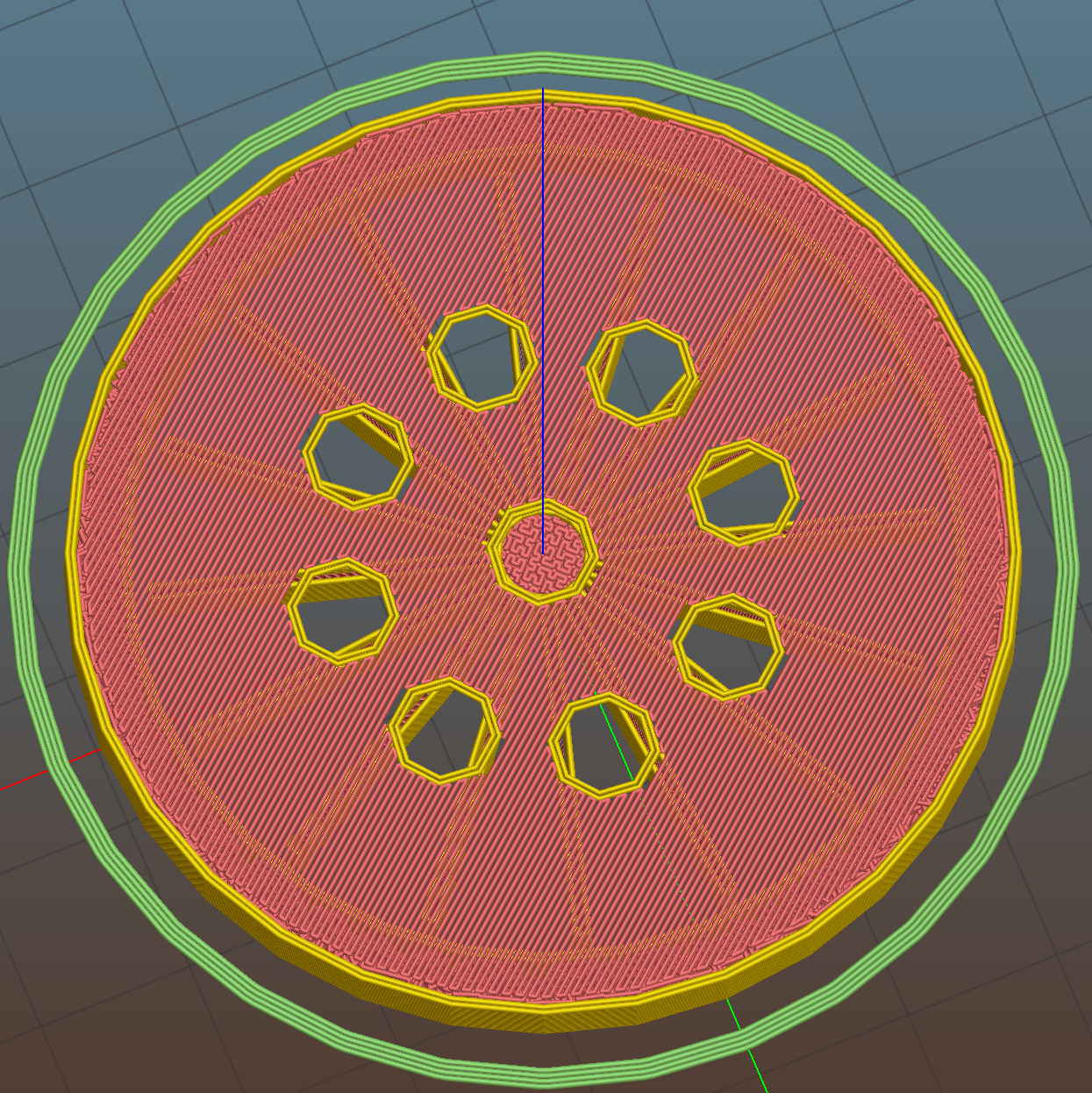
    The Slic3r preview looking down through the layer just over the support shows that the perimeter of those LED holes doesn’t have much support:

    Ring Light Mount - Slic3r preview - bridge layer
    Ring Light Mount – Slic3r preview – bridge layer

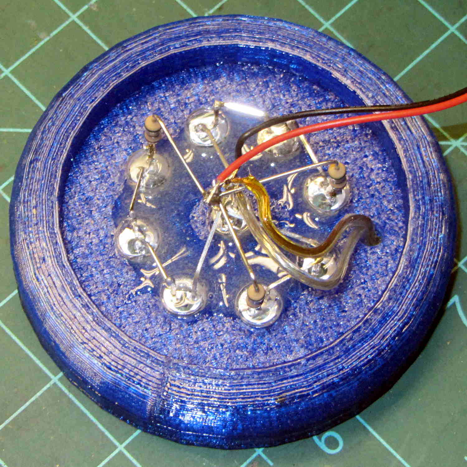
    The obvious threads drooped in the predictable way, so I just clipped them off, sanded the high spots into submission, and epoxied everything in place:

    Ring Light Mount - LED wiring
    Ring Light Mount – LED wiring

    That nice Hilbert Curve infill is completely wasted inside the OEM shade, but the smooth curve around the rim had to be on the top surface.

    Rather than beefing up the support, you should print the bottom ring (or the top rim) separately, then glue it back on, but I wanted to see how well simple support worked with PETG.

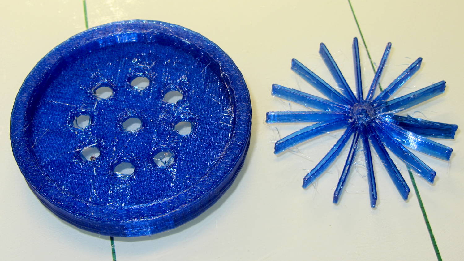
    It came out reasonably well:

    Ring Light Mount - support spider
    Ring Light Mount – support spider

    That’s far more hair than usual, even for PETG, because I made the spider’s legs exactly three thread widths wide. Slic3r reduced the single infill thread to, literally, a hair that didn’t stick to the platform; the model now has four-thread-wide legs.

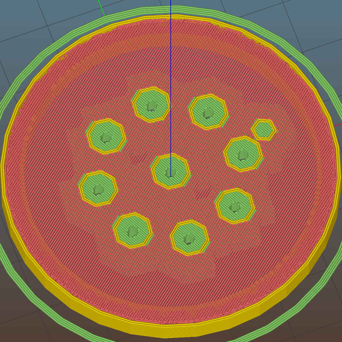
    Slic3r’s automatic support would do a better job of holding up the underside, albeit with more plastic and printing time:

    Ring Light Mount - Slic3r preview - auto support
    Ring Light Mount – Slic3r preview – auto support

    The top view looks about like you’d expect:

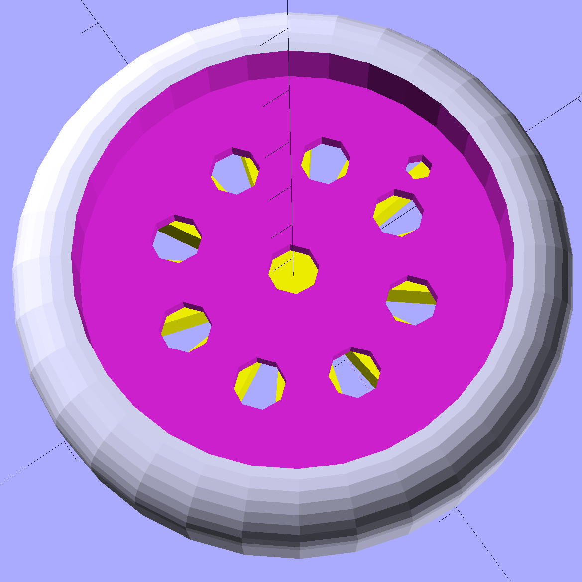
    Ring Light Mount - solid model - top
    Ring Light Mount – solid model – top

    Those two solid models show the small hole for the LED ring wiring, which I drilled into the as-printed plastic. The original layout included just the LED ring, with the wire through a big central hole, but then I realized the wall wart had enough moxie for a few more LEDs. So it goes.

    Anyhow, the lamp provides just enough illumination below my big monitors to suffice. The gooseneck might not be quite long enough, but that’ll be another project…

    The OpenSCAD source code:

    // LED Ring Light Mount
    // Ed Nisley KE4ZNU October 2015
    
    DoSupport = true;
    
    //- Extrusion parameters must match reality!
    
    ThreadThick = 0.25;
    ThreadWidth = 0.40;
    
    HoleWindage = 0.2;
    
    Protrusion = 0.1;			// make holes end cleanly
    
    inch = 25.4;
    
    function IntegerMultiple(Size,Unit) = Unit * ceil(Size / Unit);
    
    //----------------------
    // Dimensions
    
    NumSides = 8*4;						// number of sides on each "cylinder"
    
    LENGTH = 0;
    ID = 1;
    OD = 2;
    
    Shade = [6.0,45.2,47.5];			// threaded end of OEM lamp shade
    RingLED = [4.5,36.0,51.0];
    
    SpotLED = [2.0,0,5.0];				// discrete LEDs in center
    NumSpots = 8;						// discrete LEDs around the one in the middle
    
    Support = [(RingLED[LENGTH] - 1*ThreadThick),0,(RingLED[OD] - 4*ThreadWidth)];
    NumSupports = NumSides/2;
    
    ThreadBase = RingLED[LENGTH] + SpotLED[LENGTH];
    OAHeight = ThreadBase + Shade[LENGTH];
    
    //----------------------
    // Useful routines
    
    module PolyCyl(Dia,Height,ForceSides=0) {			// based on nophead's polyholes
    
      Sides = (ForceSides != 0) ? ForceSides : (ceil(Dia) + 2);
    
      FixDia = Dia / cos(180/Sides);
    
      cylinder(r=(FixDia + HoleWindage)/2,
               h=Height,
    	   $fn=Sides);
    }
    
    //----------------------
    // Build it
    
    	difference() {
    		union() {																				// overall shape
    			translate([0,0,ThreadBase])
    				rotate_extrude(convexity = 2, $fn=NumSides)
    					translate([Shade[OD]/2,0])
    						circle(r=Shade[LENGTH],$fn=NumSides);
    			cylinder(d=(Shade[OD] + 2*Shade[LENGTH]),h=ThreadBase,$fn=NumSides);
    			translate([0,0,ThreadBase])
    				cylinder(d=Shade[OD],h=Shade[LENGTH],$fn=NumSides);
    		}
    		
    		translate([0,0,ThreadBase - Protrusion])
    			cylinder(d=(Shade[ID] + HoleWindage),h=(Shade[LENGTH] + 2*Protrusion),$fn=NumSides);	// opening for shade thread
    			
    		translate([0,0,-Protrusion])
    			cylinder(d=(RingLED[OD] + HoleWindage),h=(RingLED[LENGTH] + Protrusion),$fn=NumSides);	// opening for LED ring
    			
    		rotate(180/NumSides)																		// LED ring power wire
    			translate([RingLED[ID]/2,0,0])
    				rotate(180/6)
    					PolyCyl(2.5,OAHeight,6);
    			
    		rotate(180/8  - 180/NumSides)
    			PolyCyl(SpotLED[OD],OAHeight,8);														// central LED SpotLED
    			
    		for (i=[0:NumSpots-1])																		// surrounding spots
    			rotate(i*360/NumSpots - 180/NumSides)
    				translate([(RingLED[ID] - 2*SpotLED[OD])/2,0,0])
    						rotate(180/8)
    							PolyCyl(SpotLED[OD],OAHeight,8);
    	}
    	
    //-- Support structure
    
    	if (DoSupport)
    		color("Yellow")
    		rotate(180/NumSides)													// align bars to flat internal faces
    			for (i=[0:NumSupports/2 - 1]) {
    				rotate(i * 360 / NumSupports)
    					translate([0,0,Support[LENGTH]/2])
    						cube([Support[OD],4*ThreadWidth,Support[LENGTH]],center=true);
    			}
    
    
  • Stabbing Guides

    Many of my solid models have holes for alignment pins made from filament snippets that let me glue the pieces together with near-perfect registration:

    Alignment Hole and Pin
    Alignment Hole and Pin

    A reader who designs oil-field equipment for a living pointed out that, in his world, they’re called “stabbing guides”:

    Stabbing_Point_on_Leg_1
    Stabbing_Point_on_Leg_1

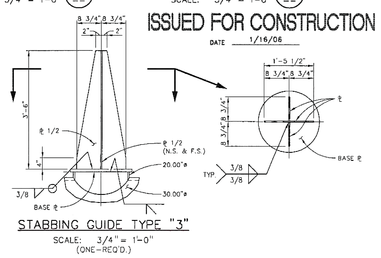
    He specifies steel plate and welding instructions:

    Stabbing_Guide_Type_3
    Stabbing_Guide_Type_3

    Stabbing guides for large modules may rise 25 feet above the deck plates…

    After they install all the little bits on a “part” like this:

    Generator Module - during assembly
    Generator Module – during assembly

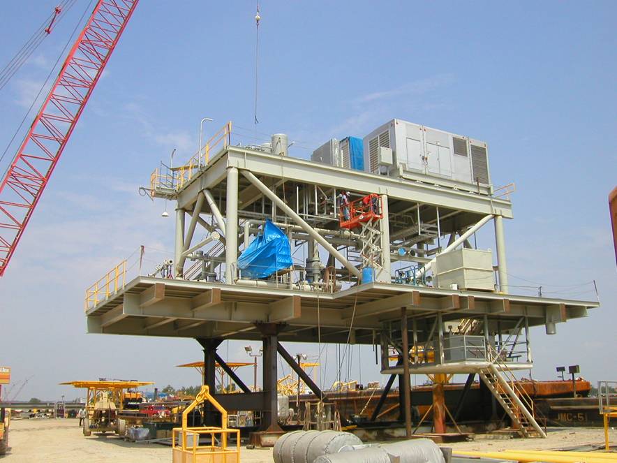
    It fits neatly atop the stabbing guides and gets welded to a somewhat larger structure:

    Generator Module - installed
    Generator Module – installed

    No sissy plastic for him!

    My puny pins don’t qualify as stabbing guides, but forgive me if I sneak the term in every now and then…

    Thanks, Tom!

  • Swept Claw Model

    Our Larval Engineer asked for help with an OpenSCAD model of a 3D printable claw that, she says, has nothing at all to do with the upcoming Night of Little Horrors. Not having had an excuse to fiddle with the new (and lightly documented) sweep() functions, I gnawed on the sweep-drop.scad example until this popped out:

    Swept Claw - solid model
    Swept Claw – solid model

    That might be too aggressively sloped up near the top, but it’s a start.

    The OpenSCAD source code:

    use <sweep.scad>
    use <scad-utils/transformations.scad>
    
    function shape() = [[0,-25],[0,25],[100,0]];
    
    function path(t) = [100*(1+sin(-90-t*90)), 0, (100 * t)];
    
    step = 0.01;
    
    path_transforms = [for (t=[0:step:1-step]) 
        translation(path(t)) * 
        scaling([0.5*(1-t) + 0.1,0.75*(1-t) + 0.1,1])];
        
    sweep(shape(), path_transforms);


    It’s perfectly manifold and slices just as you’d expect; you could affix it to a mounting bracket easily enough.

    Some notes on what’s going on…

    The t index determines all the other values as a function of the layer from the base at t=0 to the top at t=0.99.

    The shape() defines the overall triangular blade cross-section at the base; change the points / size to make it look like you want.

    The path() defines the XYZ translation of each slab that’s extruded from the shape() cross-section. I think the Z value sets the offset & thickness of each slab. The constant 100 in the X value interacts with the overall size of the shape(). The 90 values inside the sin() function set the phase & scale t so the claw bends the right way; that took some fiddling.

    The parameters in scaling() determine how the shape() shrinks along the path() as a function of the t parameter. The 0.1 Finagle Constants prevent the claw from tapering to a non-printable point at the tip. I think the Z value must be 1.000 to avoid weird non-manifold issues: the slabs must remain whatever thickness the sweep functions set them to be.

    It compiles & renders almost instantly: much faster than I expected from the demos.

    The folks who can (and do!) figure that kind of model (and the libraries behind it) from first principles have my undying admiration!

  • Sony HDR-AS30V Tripod Mount

    For reasons not relevant here, I need a tripod mount for the Sony AS-30V that’s not quite so constraining as Sony’s Official skeleton mount + right-angle tripod bracket:

    Sony HDR-AS30V - skeleton tripod mount
    Sony HDR-AS30V – skeleton tripod mount

    I must run a cable from the micro-HDMI port behind the hatch on the bottom of the camera to a display, but the Sony mount puts the hatch directly over the tripod platform and handle. Reversing the camera points it toward the handle, which then appears in the camera’s not-quite-fisheye view. Flipping the camera upside down sends the cable out the top, where it will put what I consider undue stress on the smallest high-density connector on any of my gadgets.

    This Thingiverse model by maxspongebob is called a “Windshield Mount“, but has approximately the right features:

    Sony HDR-AS30V holder - on tripod
    Sony HDR-AS30V holder – on tripod

    The weird T-shaped dingus adapts micro- and mini-HDMI sockets to an ordinary HDMI cable (HDMI connector Types D, C, and A, respectively), serving as a placeholder for the yet-to-arrive 15 foot (probably 4.5 meter) cable.

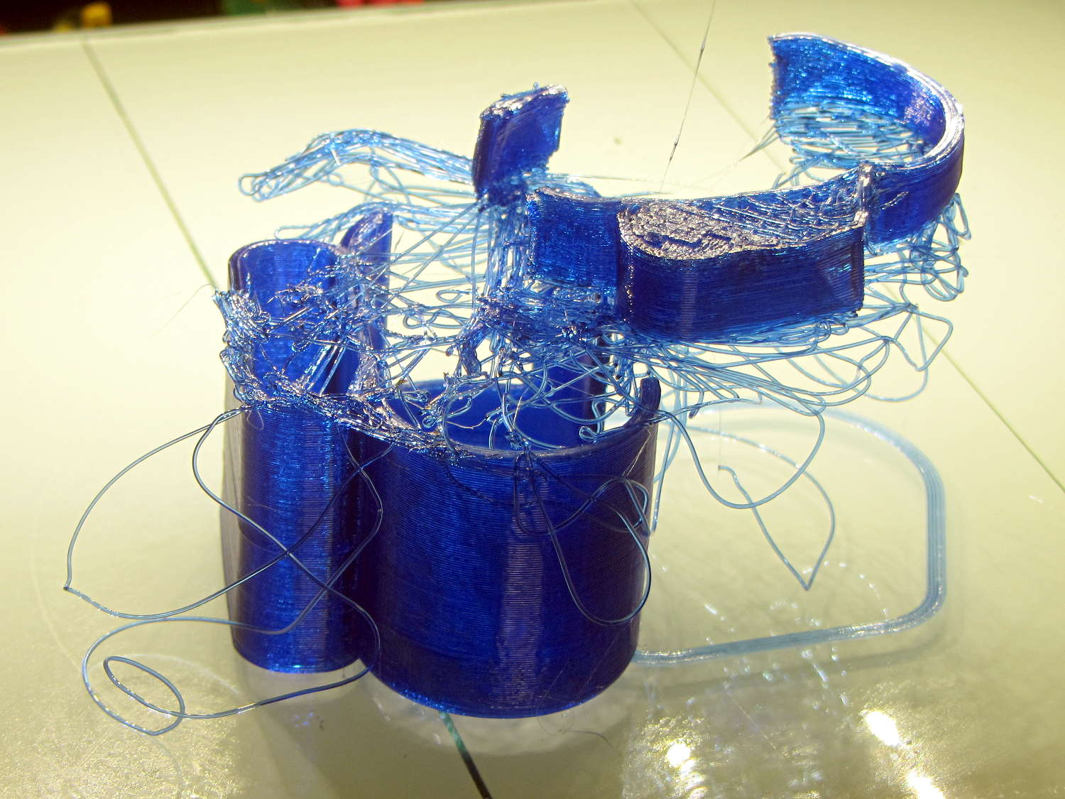
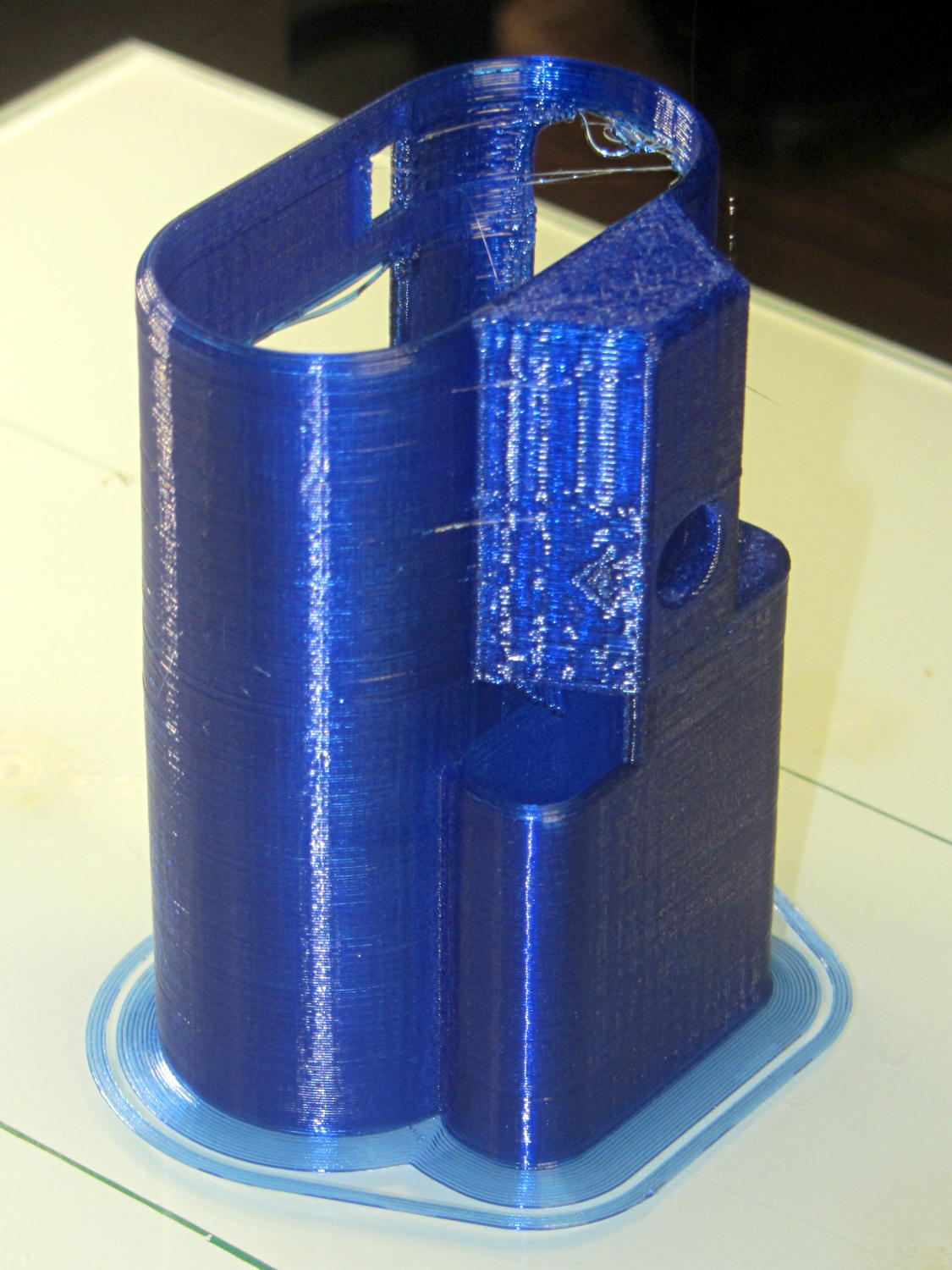
    The mount isn’t designed for easy 3D printing, as it includes thin walls with chamfered edges, close tolerances, and aggressive bridging in dimension-critical areas. The first attempt failed when the minimal footprint (you’re looking at it in the picture above) pulled off the platform when the nozzle hit the lower bridge in the battery compartment:

    Sony HDR-AS30V holder - failed print
    Sony HDR-AS30V holder – failed print

    Surrounding the first layer with a 5 mm brim provided enough traction to finish the whole thing:

    Sony HDR-AS30V holder - on platform
    Sony HDR-AS30V holder – on platform

    You can see some droopy threads across the openings; PETG bridges reasonably well, but the chamfers don’t provide good anchors. The opening for the camera hatch (on the far right rear) turned out slightly too short or, perhaps, the camera doesn’t seat quite far enough forward, which required some abrasive adjustment to accommodate the hatch.

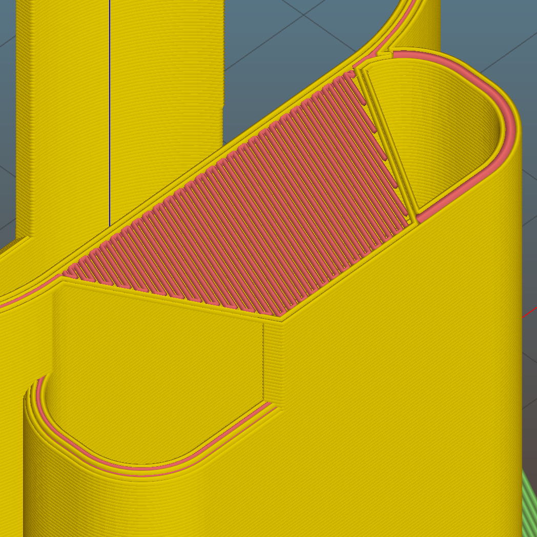
    For unknown reasons, the top end of the battery compartment has a trapezoidal bridge:

    Sony HDR-AS30V holder - trapezoidal bridge - Slic3r preview
    Sony HDR-AS30V holder – trapezoidal bridge – Slic3r preview

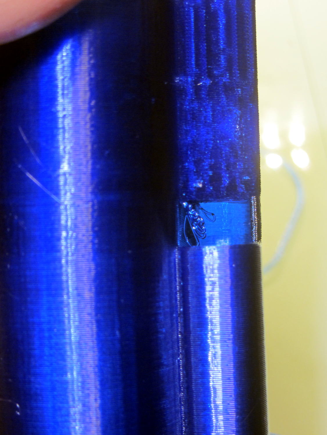
    Which simply cannot be printed:

    Sony HDR-AS30V holder - internal bridge failure
    Sony HDR-AS30V holder – internal bridge failure

    Cutting those threads out with an Xacto knife solved that problem.

    The mount attaches to the tripod with a 1/4-20 nut trapped behind the hole next to the battery compartment. I grabbed an ordinary steel nut in a long normally closed tweezers, heated it over a butane lighter flame, threaded it onto a bolt stuck through the hole, and pulled it securely into the trap with exactly zero drama.

    It has a very, very snug fit around the camera and battery that’s much better than a loose & floppy fit: there’s no positive retention latch.

    This will serve as a prototype to see if the whole project works. If so, I’ll lash something together in OpenSCAD that should print a bit better, even if it looks like my usual brackets…