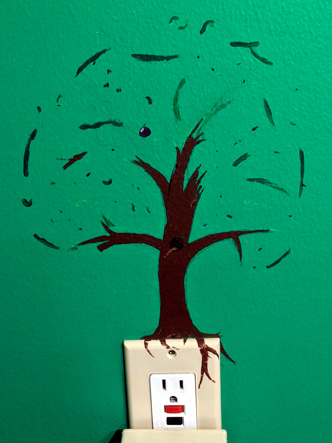
One day, long ago, this tree grew in a certain bedroom:
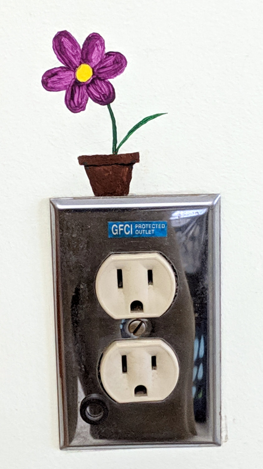
And then a flower appeared in the laundry room:
Much to our delight, she asked for forgiveness, not permission … which was, of course, granted immediately.
The Smell of Molten Projects in the Morning
Ed Nisley's Blog: Shop notes, electronics, firmware, machinery, 3D printing, laser cuttery, and curiosities. Contents: 100% human thinking, 0% AI slop.
Making the world a better place, one piece at a time
One day, long ago, this tree grew in a certain bedroom:
And then a flower appeared in the laundry room:
Much to our delight, she asked for forgiveness, not permission … which was, of course, granted immediately.
The original astable multivibrator ran from a dead CR123 primary lithium cell:

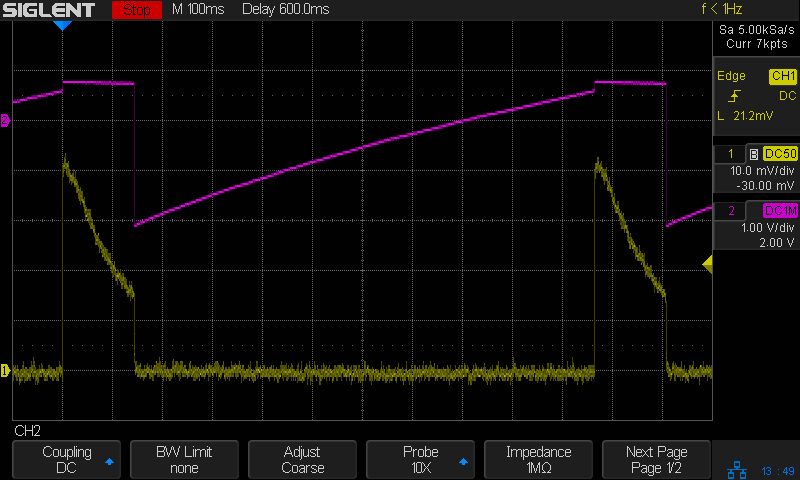
With a terminal voltage falling from barely 3 V, the LED drew about 3 mA (1 mA/div), tops, without a ballast resistor:

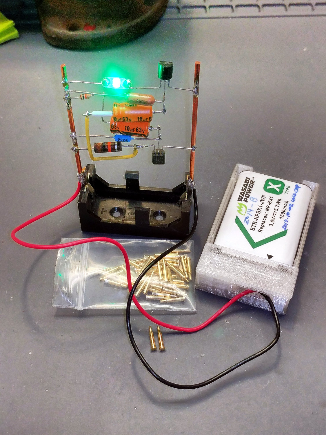
Hacking in a charged NP-BX1 secondary lithium cell boosted the supply to 4 V:
Which, diodes being the way they are, raised the LED current to nearly 400 mA (100 mA/div):
Somewhat to my surprise, a few weeks of abuse didn’t do any obvious damage to the LED, but I added a resistor while I was soldering up another holder:

There’s not quite enough room for a 1/8 W axial resistor, so why not blob in a surface-mount resistor?
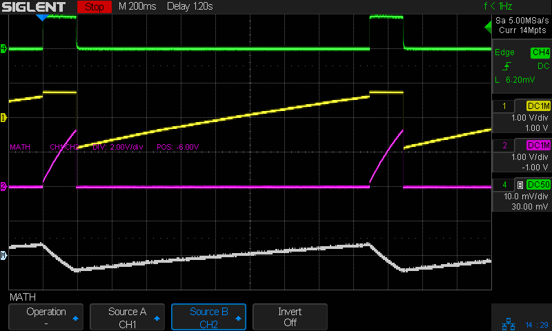
Which cuts the current down to a mere 15 mA (10 mA/div) from a lithium battery at 4 V:
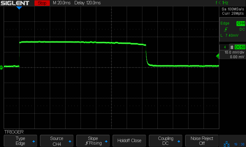
It’s still blindingly bright, but now I don’t feel bad about it.
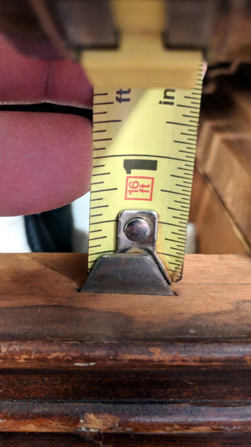
The stops aligning the top two drawers of an old desk vanished, so I got the job of replacing them. They’re hammered into the wood frame:

And stand up just enough to engage the back of the drawer face:
Back in the Basement Laboratory Shop Wing, I harvested steel strips from a defunct PC case, rubber-hammered them flat, sharpened a cold chisel (un-hardened, so it always needs sharpening), and got to work:
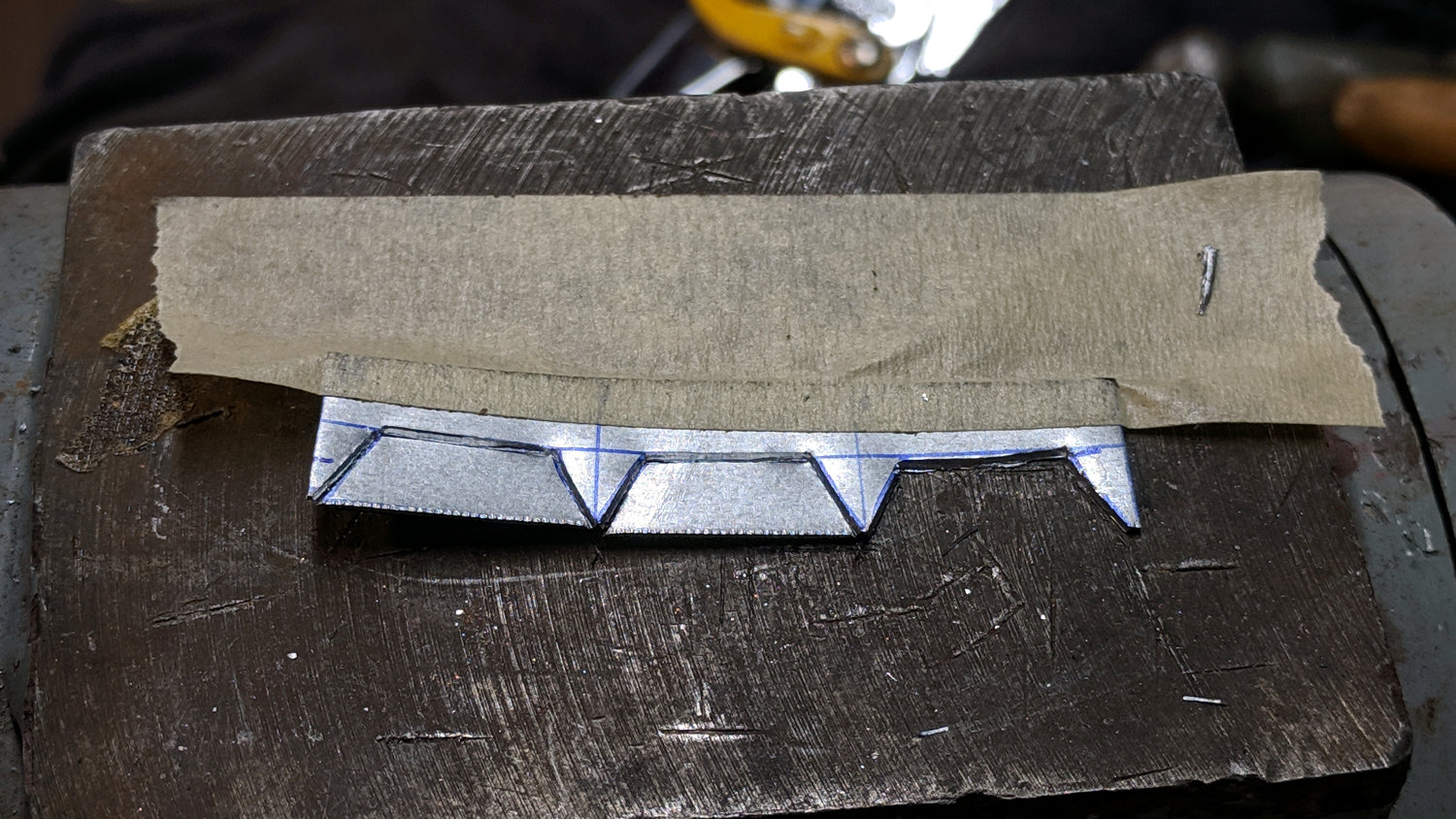
The pointy sides should have sharp edges, which you get for free with a chisel. You also get a bench full of little steel slivers perfectly suited for embedding in human flesh. Wearing eye protection is more than just a good idea, too.
Introducing what will become the visible edges to Mr Disk Sander makes them marginally less hazardous:

A slightly fuzzy picture of a test fit shows the stops should suffice:

Which they did:
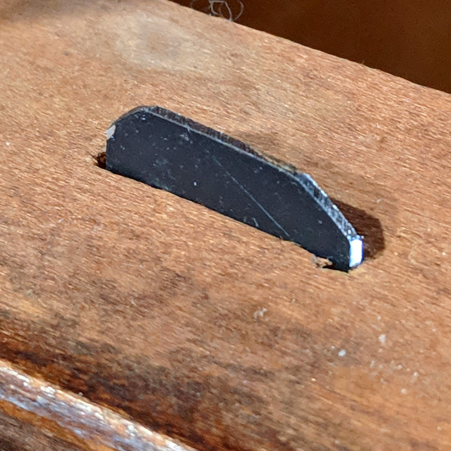
Nobody will ever notice the blob of hot melt glue behind each one:

Done!
Adapting the NP-BX1 battery holder to use SMT pogo pins worked well:
The next step is to add sockets for those 14 AWG wires:
Start by reaming / hand-drilling all the holes to their nominal size and cleaning out the pogo pin pocket.
Solder wires to the pogo pins and thread them through the holder and lid:
That’s nice, floppy silicone-insulated 24 AWG wire, which may be a bit too thick for this purpose.
The pogo pins will, ideally, seat with the end of the body flush at the holder wall. Make it so:
Dress the wires neatly into their pocket:

Butter the bottom of the lid with epoxy, clamp in place, set it up for curing, then fill the recess:

While it’s curing, make a soldering fixture for the 14 AWG wires:
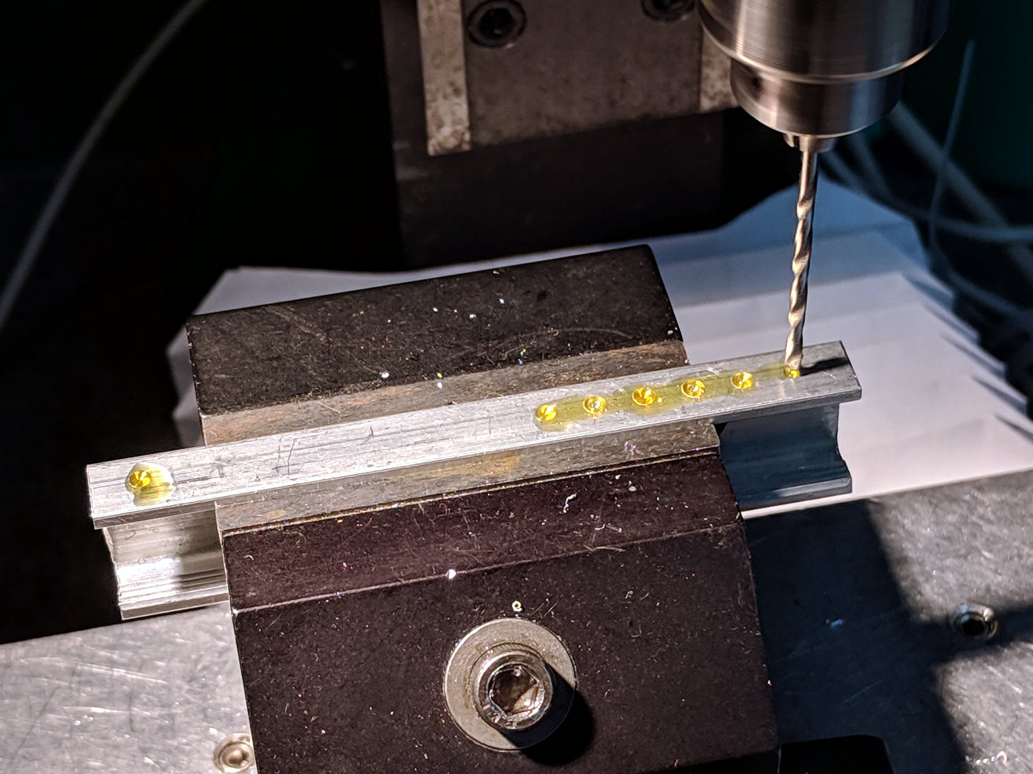
The holes are on 5 mm centers, in the expectation other battery holders will need different spacing.
Solder it up and stick the wires into the base:

Jam a battery in and It Just Works™:
The traces:
The measurement setup was a bit of a hairball:

For completeness, here’s the schematic-and-layout diagram behind the circuitry:
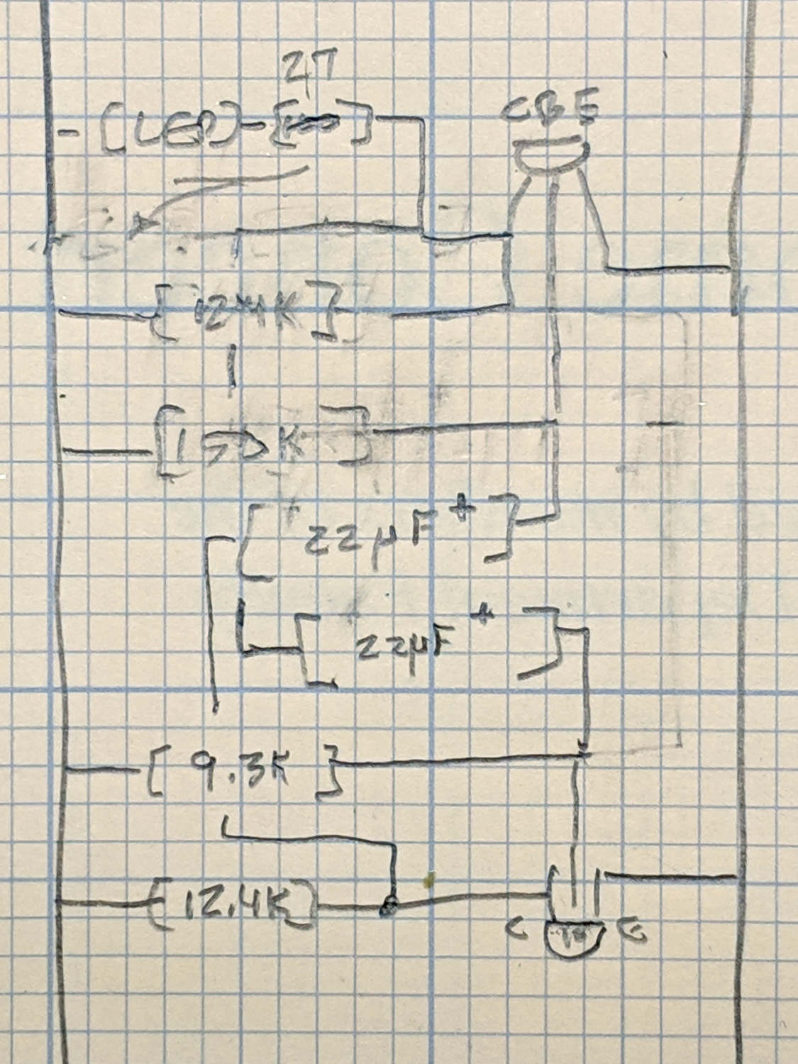
I love it when a plan comes together!
The OpenSCAD source code as a GitHub Gist:
| // Holder for Sony NP-BX1 Li-Ion battery | |
| // Ed Nisley KE4ZNU January 2013 | |
| // 2018-11-15 Adapted for wire leads from 1.5 mm test pins, added upright wire bases | |
| // Layout options | |
| Layout = "Fit"; // Show Build Fit Case Lid Pins | |
| //- Extrusion parameters – must match reality! | |
| // Print with +2 shells and 3 solid layers | |
| ThreadThick = 0.25; | |
| ThreadWidth = 0.35; | |
| HoleWindage = 0.2; | |
| function IntegerMultiple(Size,Unit) = Unit * ceil(Size / Unit); | |
| Protrusion = 0.1; // make holes end cleanly | |
| inch = 25.4; | |
| BuildOffset = 3.0; // clearance for build layout | |
| Gap = 2.0; // separation for Fit parts | |
| //- Basic dimensions | |
| WallThick = 4*ThreadWidth; // holder sidewalls | |
| BaseThick = 6*ThreadThick; // bottom of holder to bottom of battery | |
| TopThick = 6*ThreadThick; // top of battery to top of holder | |
| //- Battery dimensions – rationalized from several samples | |
| // Coordinate origin at battery contact face with key openings below contacts | |
| Battery = [43.0,30.0,9.5]; // X = length, Y = width, Z = thickness | |
| Contacts = [[-0.75,6.0,6.2],[-0.75,16.0,6.2]]; // relative to battery edge, front, and bottom | |
| ContactOC = Contacts[1].y – Contacts[0].y; | |
| ContactCenter = Contacts[0].y + ContactOC/2; | |
| KeyBlocks = [[1.75,3.70,2.90],[1.75,3.60,2.90]]; // recesses in battery face set X position | |
| //- Pin dimensions | |
| ID = 0; | |
| OD = 1; | |
| LENGTH = 2; | |
| PinShank = [1.5,2.0,6.5]; // shank, flange, compressed length | |
| PinFlange = [1.5,2.0,0.5]; // flange, length included in PinShank | |
| PinTip = [0.9,0.9,2.5]; // extended spring-loaded tip | |
| PinChannel = PinFlange[LENGTH] + 0.5; // cut behind flange for solder overflow | |
| PinRecess = 3.0; // recess behind pin flange end for epoxy fill | |
| echo(str("Contact tip dia: ",PinTip[OD])); | |
| echo(str(" .. shank dia: ",PinShank[ID])); | |
| OverTravel = 0.5; // space beyond battery face at X origin | |
| //- Holder dimensions | |
| GuideRadius = ThreadWidth; // friction fit ridges | |
| GuideOffset = 7; // from compartment corners | |
| ThumbRadius = 10.0; // thumb opening at end of battery | |
| CornerRadius = 3*ThreadThick; // nice corner rounding | |
| CaseSize = [Battery.x + PinShank[LENGTH] + OverTravel + PinRecess + GuideRadius + WallThick, | |
| Battery.y + 2*WallThick + 2*GuideRadius, | |
| Battery.z + BaseThick + TopThick]; | |
| CaseOffset = [-(PinShank[LENGTH] + OverTravel + PinRecess),-(WallThick + GuideRadius),0]; // position around battery | |
| LidOverhang = 2.0; // over top of battery for retention | |
| LidSize = [-CaseOffset.x + LidOverhang,CaseSize.y,TopThick]; | |
| LidOffset = [0.0,CaseOffset.y,0]; | |
| //- Wire struts | |
| StrutDia = 1.6; // AWG 14 = 1.6 mm | |
| StrutOC = 45; | |
| StrutSides = 3*4; | |
| StrutBase = [StrutDia,StrutDia + 4*WallThick,CaseSize.z – TopThick]; // ID = wire, OD=buildable | |
| //———————- | |
| // Useful routines | |
| module PolyCyl(Dia,Height,ForceSides=0) { // based on nophead's polyholes | |
| Sides = (ForceSides != 0) ? ForceSides : (ceil(Dia) + 2); | |
| FixDia = Dia / cos(180/Sides); | |
| cylinder(r=(FixDia + HoleWindage)/2,h=Height,$fn=Sides); | |
| } | |
| //——————- | |
| //– Guides for tighter friction fit | |
| module Guides() { | |
| translate([GuideOffset,-GuideRadius,0]) | |
| PolyCyl(2*GuideRadius,(Battery.z – Protrusion),4); | |
| translate([GuideOffset,(Battery.y + GuideRadius),0]) | |
| PolyCyl(2*GuideRadius,(Battery.z – Protrusion),4); | |
| translate([(Battery.x – GuideOffset),-GuideRadius,0]) | |
| PolyCyl(2*GuideRadius,(Battery.z – Protrusion),4); | |
| translate([(Battery.x – GuideOffset),(Battery.y + GuideRadius),0]) | |
| PolyCyl(2*GuideRadius,(Battery.z – Protrusion),4); | |
| translate([(Battery.x + GuideRadius),GuideOffset/2,0]) | |
| PolyCyl(2*GuideRadius,(Battery.z – Protrusion),4); | |
| translate([(Battery.x + GuideRadius),(Battery.y – GuideOffset/2),0]) | |
| PolyCyl(2*GuideRadius,(Battery.z – Protrusion),4); | |
| } | |
| //– Contact pins | |
| // Rotated to put them in their natural oriention | |
| // Aligned to put tip base / end of shank at Overtravel limit | |
| module PinShape() { | |
| translate([-(PinShank[LENGTH] + OverTravel),0,0]) | |
| rotate([0,90,0]) | |
| rotate(180/6) | |
| union() { | |
| PolyCyl(PinTip[OD],PinShank[LENGTH] + PinTip[LENGTH],6); | |
| PolyCyl(PinShank[ID],PinShank[LENGTH] + Protrusion,6); // slight extension for clean cuts | |
| PolyCyl(PinFlange[OD],PinFlange[LENGTH],6); | |
| } | |
| } | |
| // Position pins to put end of shank at battery face | |
| // Does not include recess access into case | |
| module PinAssembly() { | |
| union() { | |
| for (p = Contacts) | |
| translate([0,p.y,p.z]) | |
| PinShape(); | |
| translate([-(PinShank[LENGTH] + OverTravel) + PinChannel/2, // solder space | |
| ContactCenter, | |
| Contacts[0].z]) | |
| cube([PinChannel,(Contacts[1].y – Contacts[0].y),PinFlange[OD]],center=true); | |
| for (j=[-1,1]) // wire channels | |
| translate([-(PinShank[LENGTH] + OverTravel – PinChannel/2), | |
| j*ContactOC/4 + ContactCenter, | |
| Contacts[0].z – PinFlange[OD]/2]) | |
| rotate(180/6) | |
| PolyCyl(PinFlange[OD],CaseSize.z,6); | |
| } | |
| } | |
| //– Case with origin at battery corner | |
| module Case() { | |
| difference() { | |
| union() { | |
| difference() { | |
| union() { | |
| translate([(CaseSize.x/2 + CaseOffset.x), // basic case shape | |
| (CaseSize.y/2 + CaseOffset.y), | |
| (CaseSize.z/2 – BaseThick)]) | |
| hull() | |
| for (i=[-1,1], j=[-1,1], k=[-1,1]) | |
| translate([i*(CaseSize.x/2 – CornerRadius), | |
| j*(CaseSize.y/2 – CornerRadius), | |
| k*(CaseSize.z/2 – CornerRadius)]) | |
| sphere(r=CornerRadius/cos(180/8),$fn=8); // cos() fixes undersize spheres! | |
| hull() // wire strut bases | |
| for (j=[-1,1]) | |
| translate([0,j*StrutOC/2 + Battery.y/2,-BaseThick]) | |
| rotate(180/StrutSides) | |
| cylinder(d=StrutBase[OD],h=StrutBase[LENGTH],$fn=StrutSides); | |
| translate([0,Battery.y/2,StrutBase[LENGTH]/2 – BaseThick]) | |
| cube([2*StrutBase[OD],StrutOC,StrutBase[LENGTH]],center=true); | |
| } | |
| translate([-OverTravel,-GuideRadius,0]) | |
| cube([(Battery.x + GuideRadius + OverTravel), | |
| (Battery.y + 2*GuideRadius), | |
| (Battery.z + Protrusion)]); // battery space | |
| } | |
| Guides(); // improve friction fit | |
| translate([-OverTravel,-GuideRadius,0]) // battery keying blocks | |
| cube(KeyBlocks[0] + [OverTravel,GuideRadius,0],center=false); | |
| translate([-OverTravel,(Battery.y – KeyBlocks[1].y),0]) | |
| cube(KeyBlocks[1] + [OverTravel,GuideRadius,0],center=false); | |
| } | |
| translate([2*CaseOffset.x, // battery top access | |
| (CaseOffset.y – Protrusion), | |
| Battery.z]) | |
| cube([2*CaseSize.x,(CaseSize.y + 2*Protrusion),(TopThick + Protrusion)]); | |
| if (false) | |
| translate([(CaseOffset.x – Protrusion), // battery insertion allowance | |
| (CaseOffset.y – Protrusion), | |
| Battery.z]) | |
| cube([(CaseSize.x + 2*Protrusion),(CaseSize.y + 2*Protrusion),(TopThick + Protrusion)]); | |
| for (j=[-1,1]) // strut wires | |
| translate([0,j*StrutOC/2 + Battery.y/2,-(BaseThick + Protrusion)]) | |
| PolyCyl(StrutBase[ID],StrutBase[LENGTH] + 2*Protrusion,6); | |
| for (i=[-1,1], j=[-1,1]) | |
| translate([i*StrutBase[OD],j*StrutOC/2 + Battery.y/2,-(BaseThick + Protrusion)]) | |
| rotate(180/StrutSides) | |
| PolyCyl(StrutBase[OD],StrutBase[LENGTH] + 2*Protrusion,StrutSides); | |
| translate([(Battery.x – Protrusion), // remove thumb notch | |
| (CaseSize.y/2 + CaseOffset.y), | |
| (ThumbRadius)]) | |
| rotate([90,0,0]) | |
| rotate([0,90,0]) | |
| cylinder(r=ThumbRadius, | |
| h=(WallThick + GuideRadius + 2*Protrusion), | |
| $fn=22); | |
| PinAssembly(); | |
| translate([CaseOffset.x + PinRecess + Protrusion,(Contacts[1].y + Contacts[0].y)/2,Contacts[0].z]) | |
| translate([-PinRecess,0,0]) | |
| cube([2*PinRecess, | |
| (Contacts[1].y – Contacts[0].y + PinFlange[OD]), | |
| 2*PinFlange[OD]],center=true); | |
| } | |
| } | |
| // Lid position offset to match case | |
| module Lid() { | |
| difference() { | |
| translate([-LidSize.x/2 + LidOffset.x + LidOverhang,LidSize.y/2 + LidOffset.y,0]) | |
| difference() { | |
| hull() | |
| for (i=[-1,1], j=[-1,1], k=[-1,1]) | |
| translate([i*(LidSize.x/2 – CornerRadius), | |
| j*(LidSize.y/2 – CornerRadius), | |
| k*(LidSize.z – CornerRadius)]) // double thickness for flat bottom | |
| sphere(r=CornerRadius,$fn=8); | |
| translate([0,0,-LidSize.z/2]) // remove bottom | |
| cube([(LidSize.x + 2*Protrusion),(LidSize.y + 2*Protrusion),LidSize.z],center=true); | |
| translate([LidSize.x/8,0,0]) | |
| cube([LidSize.x/4,0.75*LidSize.y,4*ThreadThick],center=true); // epoxy recess | |
| } | |
| translate([0,0,-(Contacts[0].z + PinFlange[OD])]) // punch wire holes | |
| PinAssembly(); | |
| } | |
| } | |
| //——————- | |
| // Build it! | |
| if (Layout == "Case") | |
| Case(); | |
| if (Layout == "Lid") | |
| Lid(); | |
| if (Layout == "Pins") { | |
| color("Silver",0.5) | |
| PinShape(); | |
| PinAssembly(); | |
| } | |
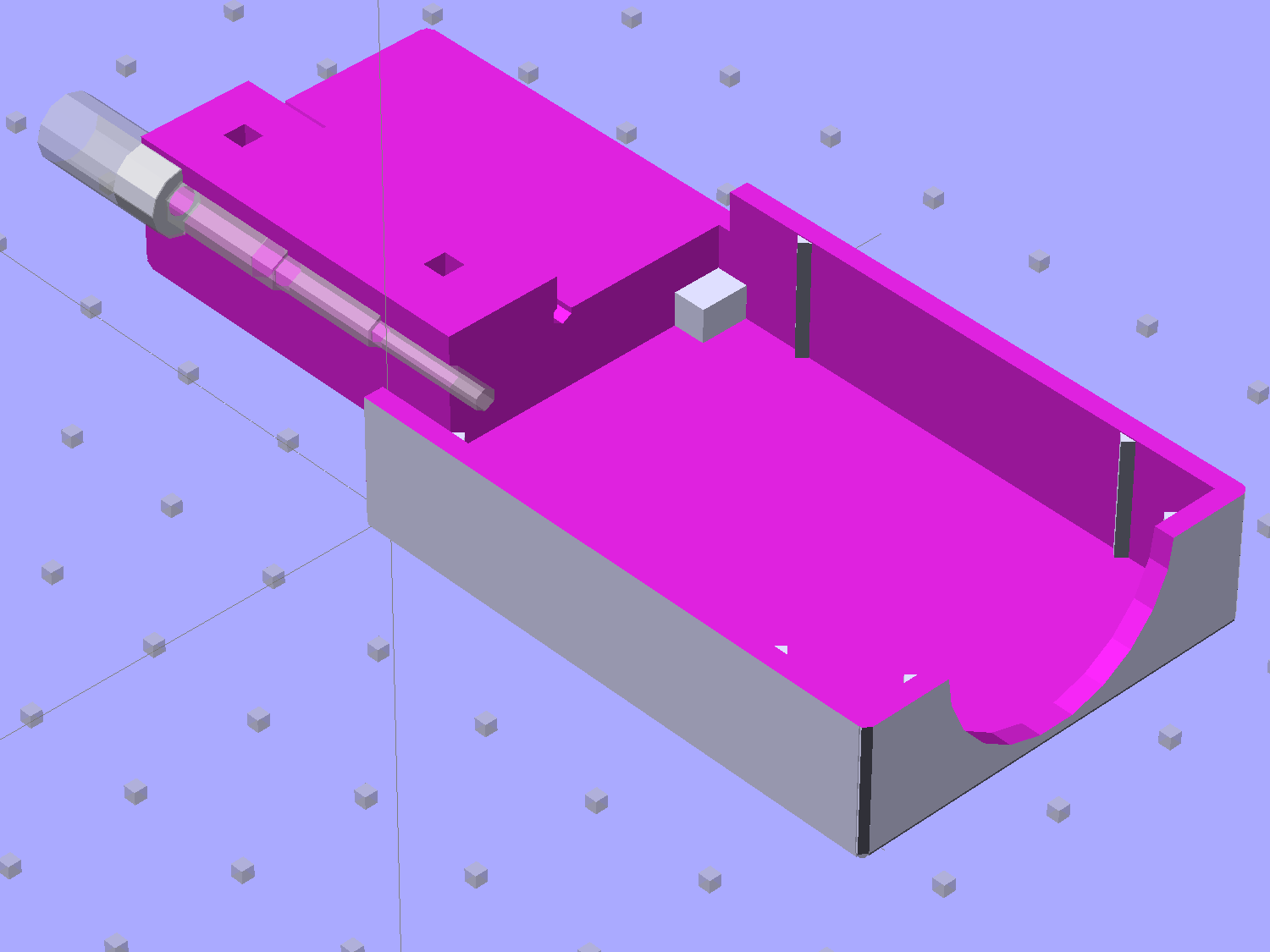
| if (Layout == "Show") { // reveal pin assembly | |
| difference() { | |
| Case(); | |
| translate([(CaseOffset.x – Protrusion), | |
| Contacts[1].y, | |
| Contacts[1].z]) | |
| cube([(-CaseOffset.x + Protrusion), | |
| CaseSize.y, | |
| (CaseSize.z – Contacts[0].z + Protrusion)]); | |
| translate([(CaseOffset.x – Protrusion), | |
| (CaseOffset.y – Protrusion), | |
| 0]) | |
| cube([(-CaseOffset.x + Protrusion), | |
| Contacts[0].y + Protrusion – CaseOffset.y, | |
| CaseSize.z]); | |
| } | |
| translate([0,0,Battery.z + Gap]) | |
| Lid(); | |
| color("Silver",0.15) | |
| PinAssembly(); | |
| } | |
| if (Layout == "Build") { | |
| translate([-(CaseSize.x/2 + CaseOffset.x),-(CaseOffset.y – BuildOffset),BaseThick]) | |
| Case(); | |
| translate([CaseSize.x/2,-LidSize.x/2,0]) | |
| rotate(90) | |
| Lid(); | |
| } | |
| if (Layout == "Fit") { | |
| Case(); | |
| translate([0,0,(Battery.z + Gap)]) | |
| Lid(); | |
| color("Silver",0.25) | |
| PinAssembly(); | |
| } | |
As part of converting the halogen desk lamp to LEDs, I replaced the hulking iron transformer with a flatter counterweight:
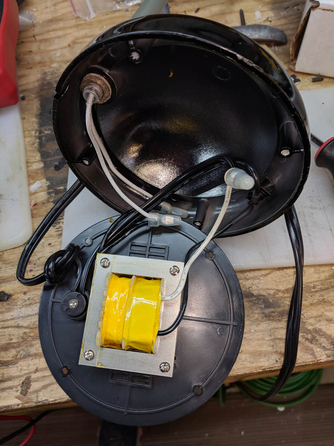
Under normal circumstances, you’d use something like steel or lead sheets, but Tiny Bandsaw™ can’t cut any appreciable thickness of steel and I gave away my entire lead stockpile, so I sawed disks from a pile of non-stick pancake griddles and drilled suitable mounting holes:

Another disk (from a formal aluminum sheet!) goes into the lamp head, with a trio of 3W COB LEDs epoxied in place:

The other side of the disk sports a heatsink harvested from a PC, also epoxied in place:

Realizing the head required only a little filing to accommodate the heatsink sealed both their fates.
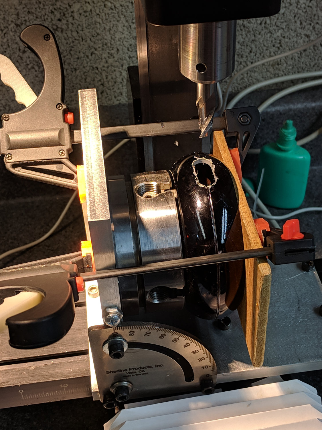
A test firing showed the heatsink needed more airflow, which didn’t come as much of a surprise, so I milled slots in the lamp head:
Deburring the holes, blackening the sides with a Sharpie, and tucking a bit of black window screen behind the opening made the vents look entirely professional.
The small dome in the base originally cleared the transformer and now holds the entire 10 W LED driver, along with all the wiring, atop the counterweight sheets:

A cork pad covers the base for a bit of non-skid action:

I couldn’t convince myself filling in those sectors would improve anything, so I didn’t.
And then It Just Worked:

All without a trace of solid modeling or G-Code …
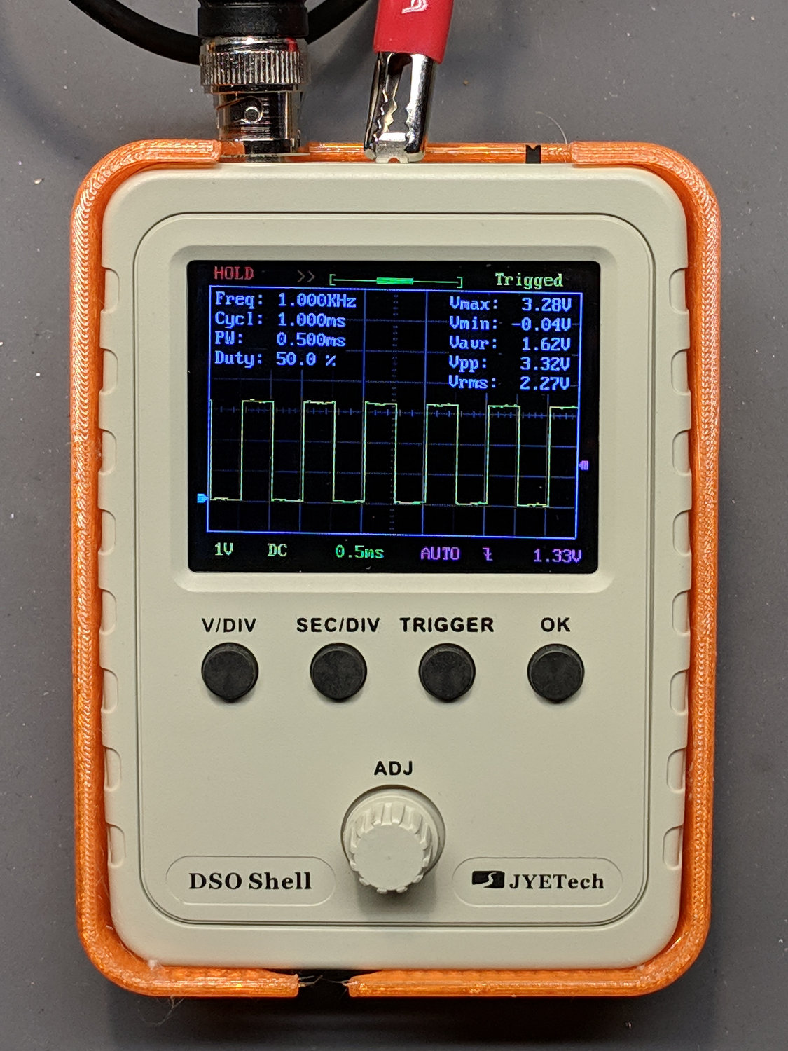
With the DSO150 scope running, I printed Geoff’s DSO150 case + battery holder from Thingiverse, added a few bits & pieces from the heap, and came up with a completely portable scope:
The only scope mod consists of embedding a JST-ish connector in the back panel:

Then soldering it to the battery pads and applying generous hot-melt glue blobs:

Add a scrap 18650 Li-Ion cell, a regulated boost converter, and a switch:
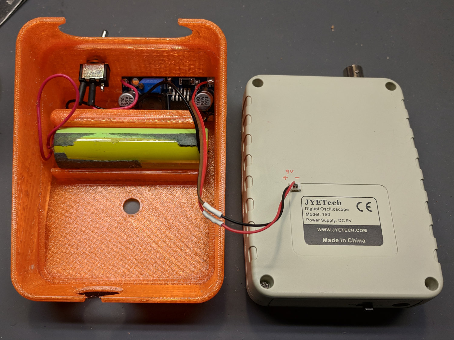
The switch is directly below the DSO150 BNC connector to get a little protection for its handle, which would otherwise stick out in harm’s way. This being an afterthought, I drilled the switch hole, rather than modify the solid model.
Some testing with a bench supply showed that the DSO150 will not operate correctly from the voltages produced by a pair of lithium cells, despite what you’d think from looking at the case. Below 8 V, the internally generated negative supply becomes larger than the positive supply, so the 0 V point isn’t properly centered and the scope loses headroom for large signals; monitoring the internal 3.3 V test signal makes the problem painfully obvious.
More color commentary from my summary email:
I’ve occasionally wanted a portable scope and now I have one!
The original camera battery test fixtures used contact pins conjured from hulking gold-plated connector pins and coil springs:
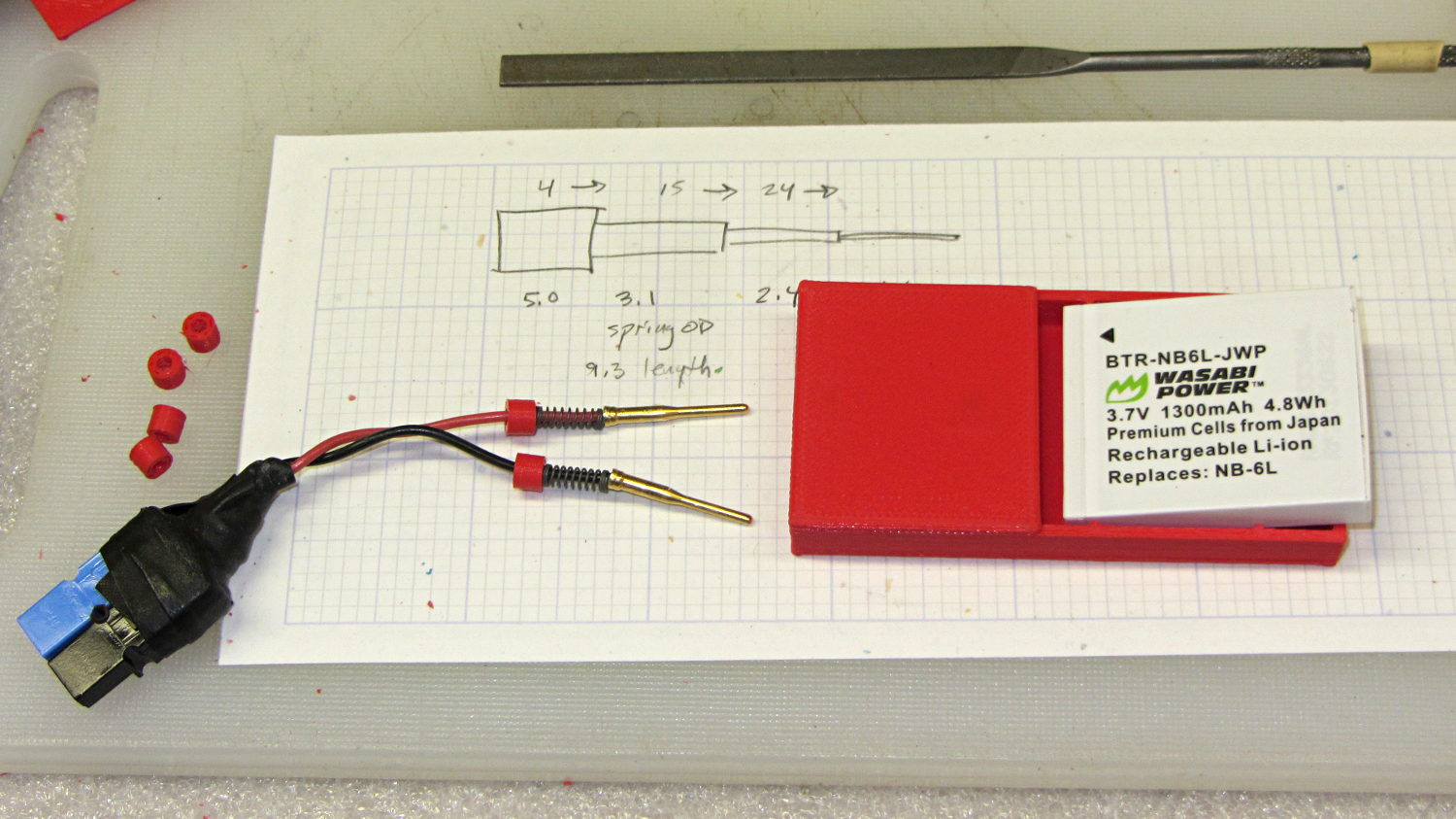
The Sony HDR-AS30V camera chewed up and spat out a handful of batteries, all tested in the NP-BX1 test fixture:
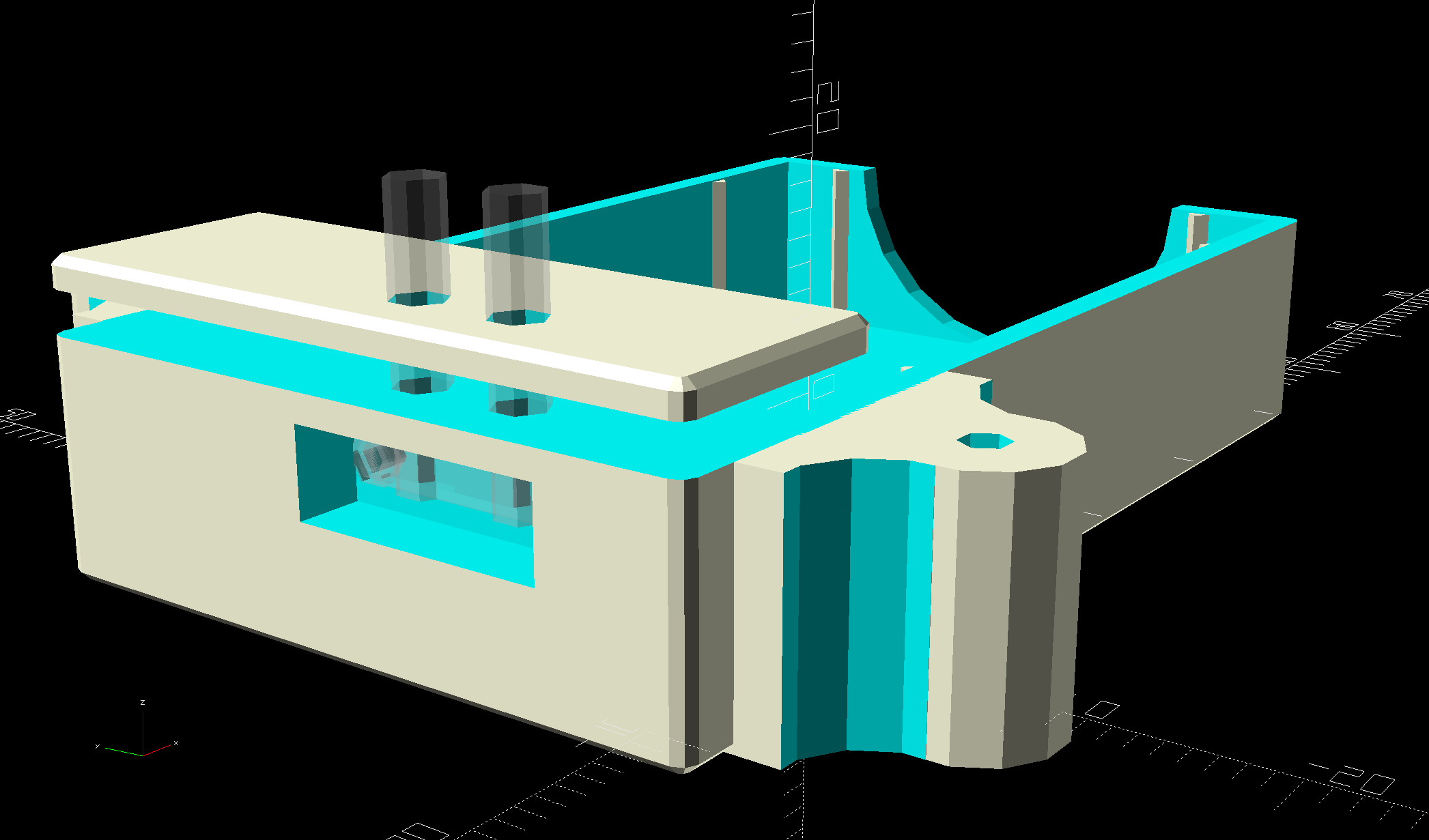
Nowadays, SMT pogo pins produce a much more compact holder, so I figured I could put all those batteries to good use:
That’s the long-suffering astable multivibrator, still soldered to its CR123A holder.
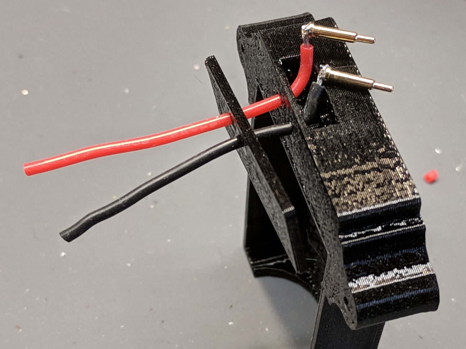
Obviously, the battery holder should grow ears to anchor the 14 AWG copper posts and would look better in black PETG:

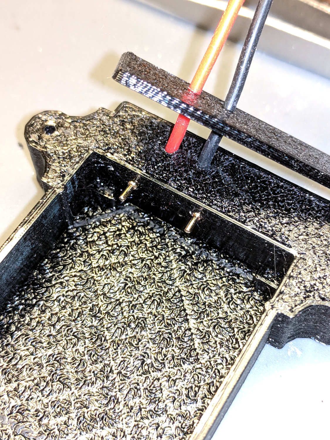
The battery lead wires get soldered to the ends of the pogo pins and are recessed into the slot in the end of the fixture. I used clear epoxy to anchor everything in place.
Fits perfectly and works fine!
The OpenSCAD source code as a GitHub Gist:
| // Holder for Sony NP-BX1 Li-Ion battery | |
| // Ed Nisley KE4ZNU January 2013 | |
| // 2018-11-15 Adapted for wire leads from 1.5 mm test pins, added upright wire bases | |
| // Layout options | |
| Layout = "Show"; // Show Build Fit Case Lid Pins | |
| //- Extrusion parameters – must match reality! | |
| // Print with +2 shells and 3 solid layers | |
| ThreadThick = 0.25; | |
| ThreadWidth = 0.35; | |
| HoleWindage = 0.2; | |
| function IntegerMultiple(Size,Unit) = Unit * ceil(Size / Unit); | |
| Protrusion = 0.1; // make holes end cleanly | |
| inch = 25.4; | |
| BuildOffset = 3.0; // clearance for build layout | |
| Gap = 2.0; // separation for Fit parts | |
| //- Battery dimensions – rationalized from several samples | |
| // Coordinate origin at battery contact face with key openings below contacts | |
| Battery = [43.0,30.0,9.5]; // X = length, Y = width, Z = thickness | |
| Contacts = [[-0.75,6.0,6.2],[-0.75,16.0,6.2]]; // relative to battery edge, front, and bottom | |
| KeyBlocks = [[1.75,3.70,2.90],[1.75,3.60,2.90]]; // recesses in battery face set X position | |
| //- Pin dimensions | |
| ID = 0; | |
| OD = 1; | |
| LENGTH = 2; | |
| PinShank = [1.5,2.0,6.5]; // shank, flange, compressed length | |
| PinFlange = [1.5,2.0,0.5]; // flange, length included in PinShank | |
| PinTip = [0.9,0.9,2.5]; // extended spring-loaded tip | |
| PinChannel = PinFlange[LENGTH] + 0.5; // cut behind flange for solder overflow | |
| PinRecess = 3.0; // recess behind pin flange end for epoxy fill | |
| echo(str("Contact tip dia: ",PinTip[OD])); | |
| echo(str(" .. shank dia: ",PinShank[ID])); | |
| OverTravel = 0.5; // space beyond battery face at X origin | |
| //- Holder dimensions | |
| GuideRadius = ThreadWidth; // friction fit ridges | |
| GuideOffset = 7; // from compartment corners | |
| WallThick = 4*ThreadWidth; // holder sidewalls | |
| BaseThick = 6*ThreadThick; // bottom of holder to bottom of battery | |
| TopThick = 6*ThreadThick; // top of battery to top of holder | |
| ThumbRadius = 10.0; // thumb opening at end of battery | |
| CornerRadius = 3*ThreadThick; // nice corner rounding | |
| CaseSize = [Battery.x + PinShank[LENGTH] + OverTravel + PinRecess + GuideRadius + WallThick, | |
| Battery.y + 2*WallThick + 2*GuideRadius, | |
| Battery.z + BaseThick + TopThick]; | |
| CaseOffset = [-(PinShank[LENGTH] + OverTravel + PinRecess),-(WallThick + GuideRadius),0]; // position around battery | |
| LidOverhang = 2.0; // over top of battery for retention | |
| LidSize = [-CaseOffset.x + LidOverhang,CaseSize.y,TopThick]; | |
| LidOffset = [0.0,CaseOffset.y,0]; | |
| //———————- | |
| // Useful routines | |
| module PolyCyl(Dia,Height,ForceSides=0) { // based on nophead's polyholes | |
| Sides = (ForceSides != 0) ? ForceSides : (ceil(Dia) + 2); | |
| FixDia = Dia / cos(180/Sides); | |
| cylinder(r=(FixDia + HoleWindage)/2,h=Height,$fn=Sides); | |
| } | |
| //——————- | |
| //– Guides for tighter friction fit | |
| module Guides() { | |
| translate([GuideOffset,-GuideRadius,0]) | |
| PolyCyl(2*GuideRadius,(Battery.z – Protrusion),4); | |
| translate([GuideOffset,(Battery.y + GuideRadius),0]) | |
| PolyCyl(2*GuideRadius,(Battery.z – Protrusion),4); | |
| translate([(Battery.x – GuideOffset),-GuideRadius,0]) | |
| PolyCyl(2*GuideRadius,(Battery.z – Protrusion),4); | |
| translate([(Battery.x – GuideOffset),(Battery.y + GuideRadius),0]) | |
| PolyCyl(2*GuideRadius,(Battery.z – Protrusion),4); | |
| translate([(Battery.x + GuideRadius),GuideOffset/2,0]) | |
| PolyCyl(2*GuideRadius,(Battery.z – Protrusion),4); | |
| translate([(Battery.x + GuideRadius),(Battery.y – GuideOffset/2),0]) | |
| PolyCyl(2*GuideRadius,(Battery.z – Protrusion),4); | |
| } | |
| //– Contact pins | |
| // Rotated to put them in their natural oriention | |
| // Aligned to put tip base / end of shank at Overtravel limit | |
| module PinShape() { | |
| translate([-(PinShank[LENGTH] + OverTravel),0,0]) | |
| rotate([0,90,0]) | |
| rotate(180/6) | |
| union() { | |
| PolyCyl(PinTip[OD],PinShank[LENGTH] + PinTip[LENGTH],6); | |
| PolyCyl(PinShank[ID],PinShank[LENGTH] + Protrusion,6); // slight extension for clean cuts | |
| PolyCyl(PinFlange[OD],PinFlange[LENGTH],6); | |
| } | |
| } | |
| // Position pins to put end of shank at battery face | |
| // Add wire exit channel between pins | |
| // Does not include recess access | |
| module PinAssembly() { | |
| union() { | |
| for (p = Contacts) | |
| translate([0,p.y,p.z]) | |
| PinShape(); | |
| translate([-(PinShank[LENGTH] + OverTravel) + PinChannel/2, | |
| (Contacts[1].y + Contacts[0].y)/2, | |
| Contacts[0].z]) | |
| cube([PinChannel,(Contacts[1].y – Contacts[0].y),PinFlange[OD]],center=true); | |
| } | |
| } | |
| //– Case with origin at battery corner | |
| module Case() { | |
| difference() { | |
| union() { | |
| difference() { | |
| translate([(CaseSize.x/2 + CaseOffset.x), // basic case shape | |
| (CaseSize.y/2 + CaseOffset.y), | |
| (CaseSize.z/2 – BaseThick)]) | |
| hull() | |
| for (i=[-1,1], j=[-1,1], k=[-1,1]) | |
| translate([i*(CaseSize.x/2 – CornerRadius), | |
| j*(CaseSize.y/2 – CornerRadius), | |
| k*(CaseSize.z/2 – CornerRadius)]) | |
| sphere(r=CornerRadius,$fn=8); | |
| translate([-OverTravel,-GuideRadius,0]) | |
| cube([(Battery.x + GuideRadius + OverTravel), | |
| (Battery.y + 2*GuideRadius), | |
| (Battery.z + Protrusion)]); // battery space | |
| } | |
| Guides(); // improve friction fit | |
| translate([-OverTravel,-GuideRadius,0]) // battery keying blocks | |
| cube(KeyBlocks[0] + [OverTravel,GuideRadius,0],center=false); | |
| translate([-OverTravel,(Battery.y – KeyBlocks[1].y),0]) | |
| cube(KeyBlocks[1] + [OverTravel,GuideRadius,0],center=false); | |
| } | |
| translate([(-OverTravel), // battery top access | |
| (CaseOffset.y – Protrusion), | |
| Battery.z]) | |
| cube([CaseSize.x,(CaseSize.y + 2*Protrusion),(TopThick + Protrusion)]); | |
| translate([(CaseOffset.x – Protrusion), // battery insertion allowance | |
| (CaseOffset.y – Protrusion), | |
| Battery.z]) | |
| cube([(CaseSize.x + 2*Protrusion),(CaseSize.y + 2*Protrusion),(TopThick + Protrusion)]); | |
| translate([(Battery.x – Protrusion), // remove thumb notch | |
| (CaseSize.y/2 + CaseOffset.y), | |
| (ThumbRadius)]) | |
| rotate([90,0,0]) | |
| rotate([0,90,0]) | |
| cylinder(r=ThumbRadius, | |
| h=(WallThick + GuideRadius + 2*Protrusion), | |
| $fn=22); | |
| PinAssembly(); | |
| translate([CaseOffset.x + PinRecess/2 + Protrusion/2,(Contacts[1].y + Contacts[0].y)/2,Contacts[0].z]) | |
| cube([PinRecess + Protrusion, | |
| (Contacts[1].y – Contacts[0].y + PinFlange[OD]), | |
| 2*PinFlange[OD]],center=true); | |
| } | |
| } | |
| // Lid position offset to match case | |
| module Lid() { | |
| translate([-LidSize.x/2 + LidOffset.x + LidOverhang,LidSize.y/2 + LidOffset.y,0]) | |
| difference() { | |
| hull() | |
| for (i=[-1,1], j=[-1,1], k=[-1,1]) | |
| translate([i*(LidSize.x/2 – CornerRadius), | |
| j*(LidSize.y/2 – CornerRadius), | |
| k*(LidSize.z – CornerRadius)]) // double thickness for flat bottom | |
| sphere(r=CornerRadius,$fn=8); | |
| translate([0,0,-LidSize.z/2]) | |
| cube([(LidSize.x + 2*Protrusion),(LidSize.y + 2*Protrusion),LidSize.z],center=true); | |
| cube([LidSize.x/4,0.75*LidSize.y,4*ThreadThick],center=true); // epoxy recess | |
| } | |
| } | |
| //——————- | |
| // Build it! | |
| if (Layout == "Case") | |
| Case(); | |
| if (Layout == "Lid") | |
| Lid(); | |
| if (Layout == "Pins") { | |
| color("Silver",0.5) | |
| PinShape(); | |
| PinAssembly(); | |
| } | |
| if (Layout == "Show") { // reveal pin assembly | |
| difference() { | |
| Case(); | |
| translate([(CaseOffset.x – Protrusion), | |
| Contacts[1].y, | |
| Contacts[1].z]) | |
| cube([(-CaseOffset.x + Protrusion), | |
| CaseSize.y, | |
| (CaseSize.z – Contacts[0].z + Protrusion)]); | |
| translate([(CaseOffset.x – Protrusion), | |
| (CaseOffset.y – Protrusion), | |
| 0]) | |
| cube([(-CaseOffset.x + Protrusion), | |
| Contacts[0].y + Protrusion – CaseOffset.y, | |
| CaseSize.z]); | |
| } | |
| color("Silver",0.15) | |
| PinAssembly(); | |
| translate([0,0,Battery.z + Gap]) | |
| Lid(); | |
| } | |
| if (Layout == "Build") { | |
| translate([-(CaseSize.x/2 + CaseOffset.x),-(CaseOffset.y – BuildOffset),BaseThick]) | |
| Case(); | |
| translate([CaseSize.y/2,(CaseOffset.x/2 – BuildOffset),0]) | |
| rotate([0,0,90]) | |
| Lid(); | |
| } | |
| if (Layout == "Fit") { | |
| Case(); | |
| translate([0,0,(Battery.z + Gap)]) | |
| Lid(); | |
| color("Silver",0.25) | |
| PinAssembly(); | |
| } | |
