Sliding a drag knife body in a PETG holder, even after boring the plastic to fit, shows plenty of stiction along 2 mm of travel:
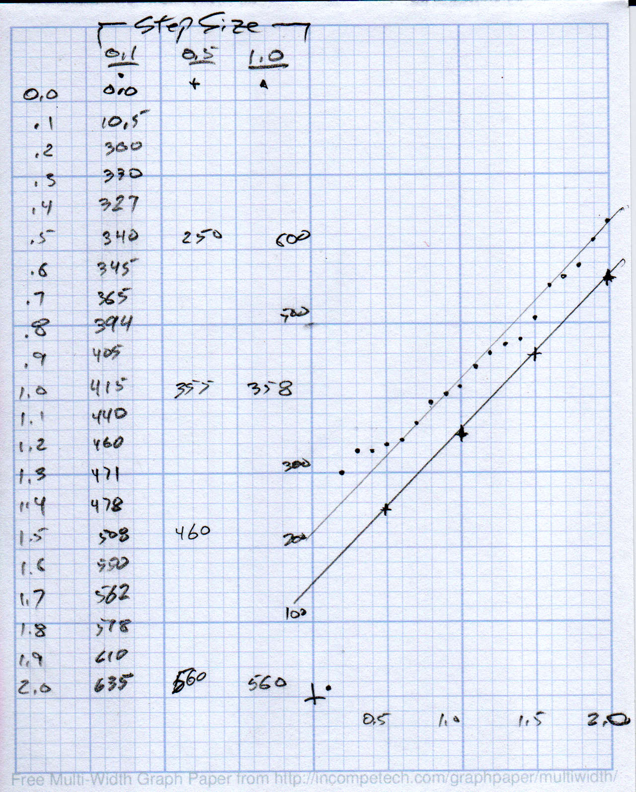
Punching the Z axis downward in 0.5 or 1.0 mm steps produced the lower line at 210 g/mm. Dividing by three springs, each one has a 70 g/mm spring constant, which may come in handy later.
The wavy upper line shows the stiction as the Z axis drops in 0.1 mm steps. The line is eyeballometrically fit to be parallel to the “good” line, but it’s obvious you can’t depend on the Z axis value to put a repeatable force on the knife.
I cranked about a turn onto the three screws to preload the springs and ensure the disk with the knife body settles onto the bottom of the holder:

The screws are M4×0.7, so one turn should apply about 140 g of preload force to the pen holder. Re-taking a few data points with a 0.5 mm step and more attention to an accurate zero position puts the intercept at 200 g, so the screws may have been slightly tighter than I expected. Close enough, anyway.
The stiction is exquisitely sensitive to the tightness of the two DW660 mount clamp screws (on the black ring), so the orange plastic disk isn’t a rigid body. No surprise there, either.
Loosening the bored slip fit would allow more lateral motion at the tip. Perhaps top-and-bottom Delrin bushings (in a taller mount) would improve the situation? A full-on linear bearing seems excessive, even to me, particularly because I don’t want to bore out a 16 mm shaft for the blade holder.
It’s certainly Good Enough™ as-is for the purpose, as I can set the cut depth to, say, 0.5 mm to apply around 250-ish g of downforce or 1.0 mm for 350-ish g. The key point is having enough Z axis compliance to soak up small table height variations without needing to scan and apply compensation.

Comments
One response to “MPCNC: Drag Knife Holder Spring Constant vs. Stiction”
[…] set dxf2gcode to use a cutting depth = 1.0 mm for about 400 g of downforce, which seems to work, although the vinyl surface showed some marks from the flat nose around the […]