Ed Nisley's Blog: Shop notes, electronics, firmware, machinery, 3D printing, laser cuttery, and curiosities. Contents: 100% human thinking, 0% AI slop.
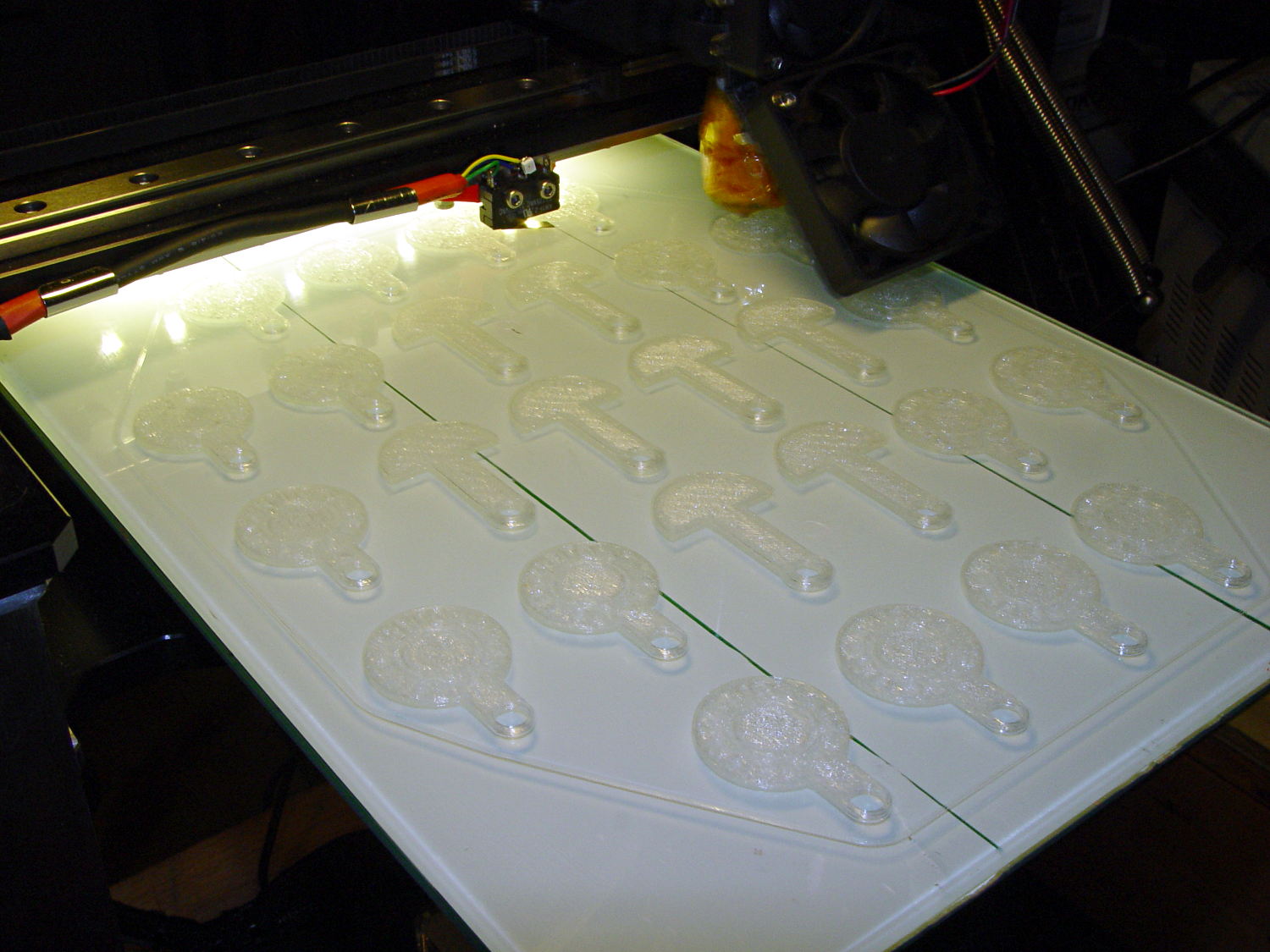
It turns out that an array of Cart Coins and Cart Releasers make a fine thickness test pattern and become useful tchotchkes when you’re done:
Cart Coins – printing
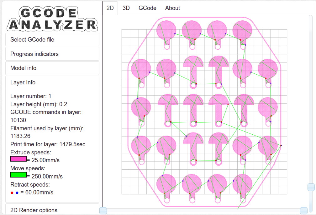
They’re a bit easier to see in the digital realm:
Cart Coins – platform layout – layer 1
The trick is that they’re both eight layers thick at 0.20 mm/layer. With the platform aligned exactly right, all the objects should measure exactly 1.60 mm thick.
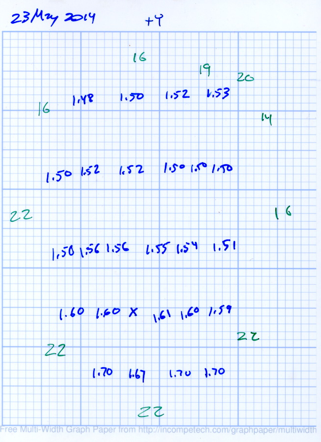
The blue numbers give the thickness measured across the stem, just above the hole, on each object:
Platform Leveling – Initial
The green numbers are the skirt thickness: 22 = 0.22 mm.
The platform has a tilt of 0.20 mm from +Y to -Y and is just about perfect from -X to +X.
The M3x0.5 adjusting screws under the (improved) platform, seen from the front (-Y) end of the platform:
M2 – Improved HBP – bottom view
The silicone plugs inside the springs are slightly compressed, so the springs are only decorative. The platform is rigidly mounted on the plugs, with only very slight compliance, and I haven’t leveled the platform in a few months.
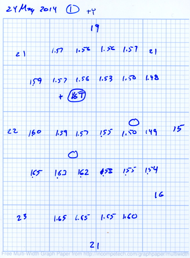
Tightening the “north” adjusting screw by 1/6 turn lowered the +Y end of the plate by about 0.05 mm and tilted the +X side slightly higher:
Platform Leveling – Adjustment 1
The skirt thicknesses are now in blue, too.
Tightening the “north” screw an additional 1/6 turn and tightening the “east” screw 1/6 turn produced an almost perfect result:
Platform Leveling – Adjustment 2
The thicknesses don’t vary quite randomly, but I think further adjustments won’t make much difference: the total range is only 0.12 mm = 1.53 to 1.65 mm. That’s pretty close to the limit of my measurement ability on the plastic pieces.
Notice that the skirt thread, which should be exactly 0.2 mm thick all around, really isn’t. I’m going to see whether a two-layer-thick skirt measures a more consistent 0.40 mm.
The whole reason I got a 3D printer in the first place was to make things that would otherwise be too difficult or tedious by hand or on a CNC mill. Most of the things I make look like brackets and I don’t do sculptures … this stuff solves problems!
Being able to go from “I need a part shaped like that” to holding the thing in my hand a few hours (or, for complex designs, days) later is empowering. Being able to adjust a dimension by changing the source code and “recompiling” to get a new part is wonderful.
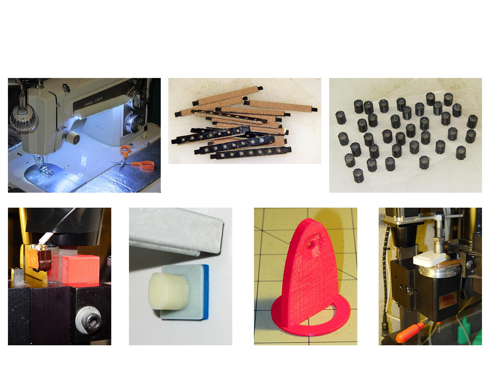
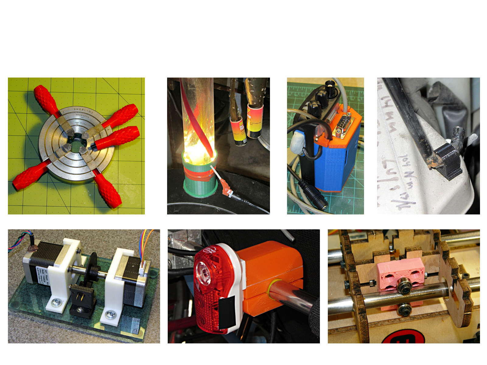
These five slides from the presentation show my answers to the question “Why would anyone want a 3D printer?” Clicky for more dots.
Things I Designed – 1Things I Designed – 2Things I Designed – 3Things I Designed – 4Things I Designed – 5
Herewith, the MHVLUG – 3D Printing Status 2104 slides (remember slides?) I’ll be using for my talk this evening at the MHVLUG meeting; you don’t get the audio track in the PDF, but the pictures may be informative.
If you believe everything you read, you might think personal 3D printing will go like this:
3D Printing 2014 – What They Say
But it requires entirely too much of this:
3D Printing 2014 – What They Dont Say
Personal 3D printing requires that you take full control:
3D Printing 2014 – Personal 3D Printing
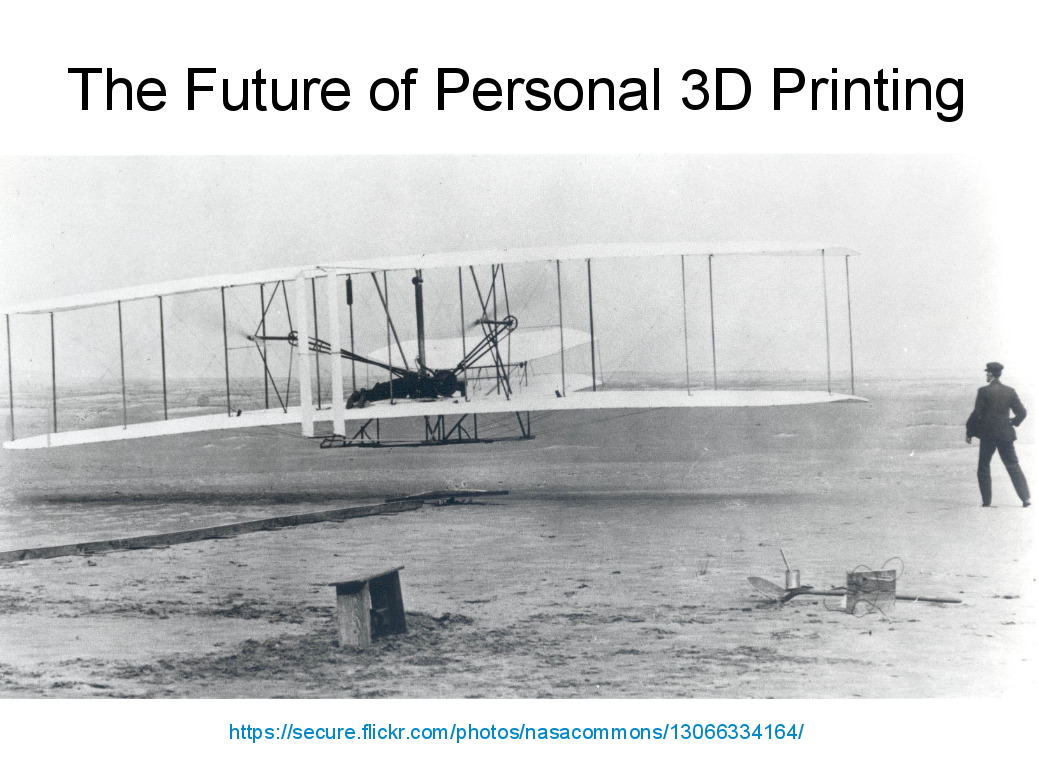
Not knowing the answers, I’ll still make some guesses about what lies ahead:
3D Printing 2014 – The Future
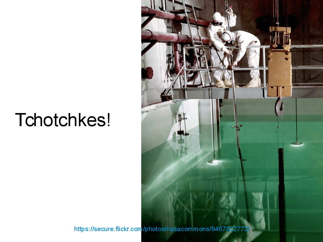
And I found the best tchotchkes ever:
3D Printing 2014 – Tchotchkes
See you there…
(The PDF has clickable links for those images, plus the 60-some-odd other slides. The plan: talk like an auctioneer for an hour!)
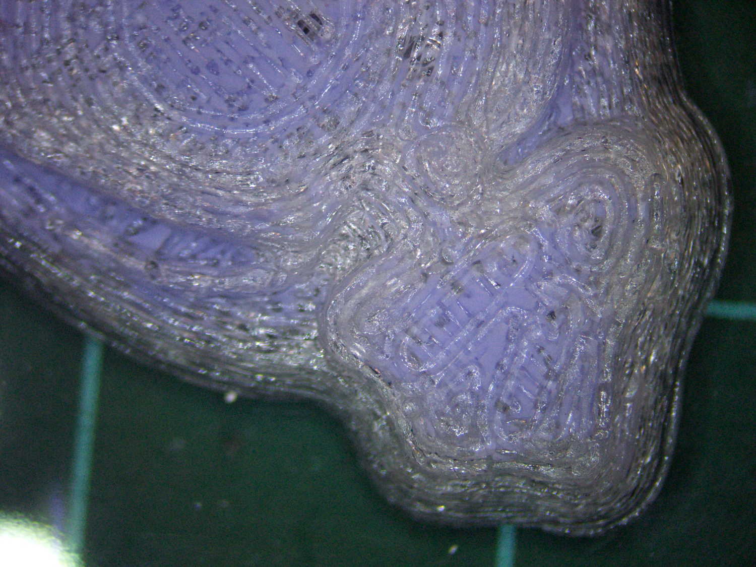
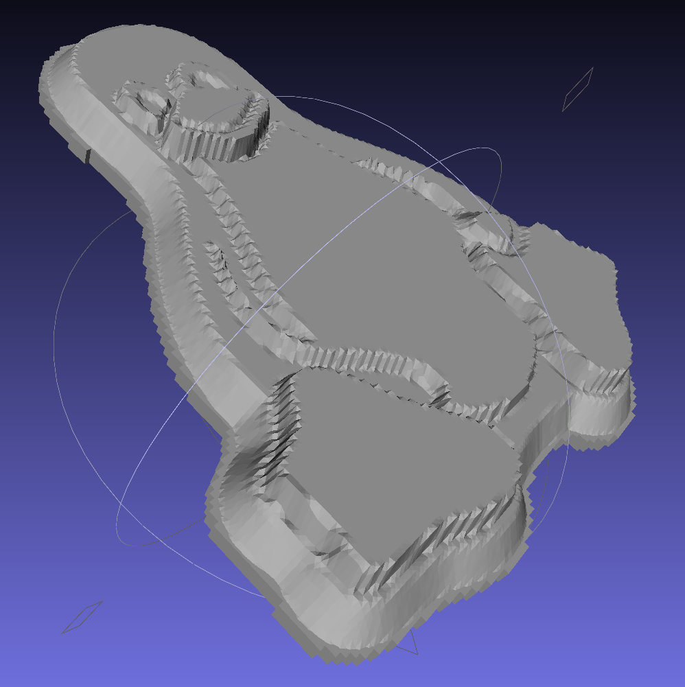
The PLA positive, after removing the silicone negative, showing the silicone below the surface:
Tux Gradient – PLA positive detail
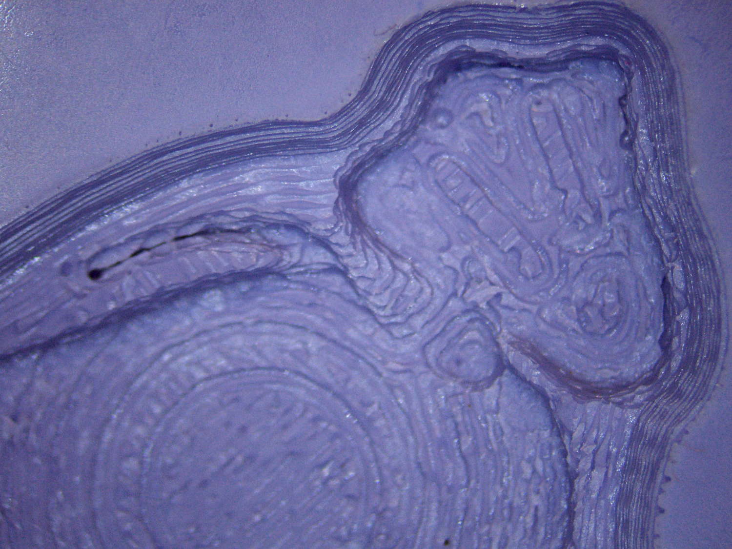
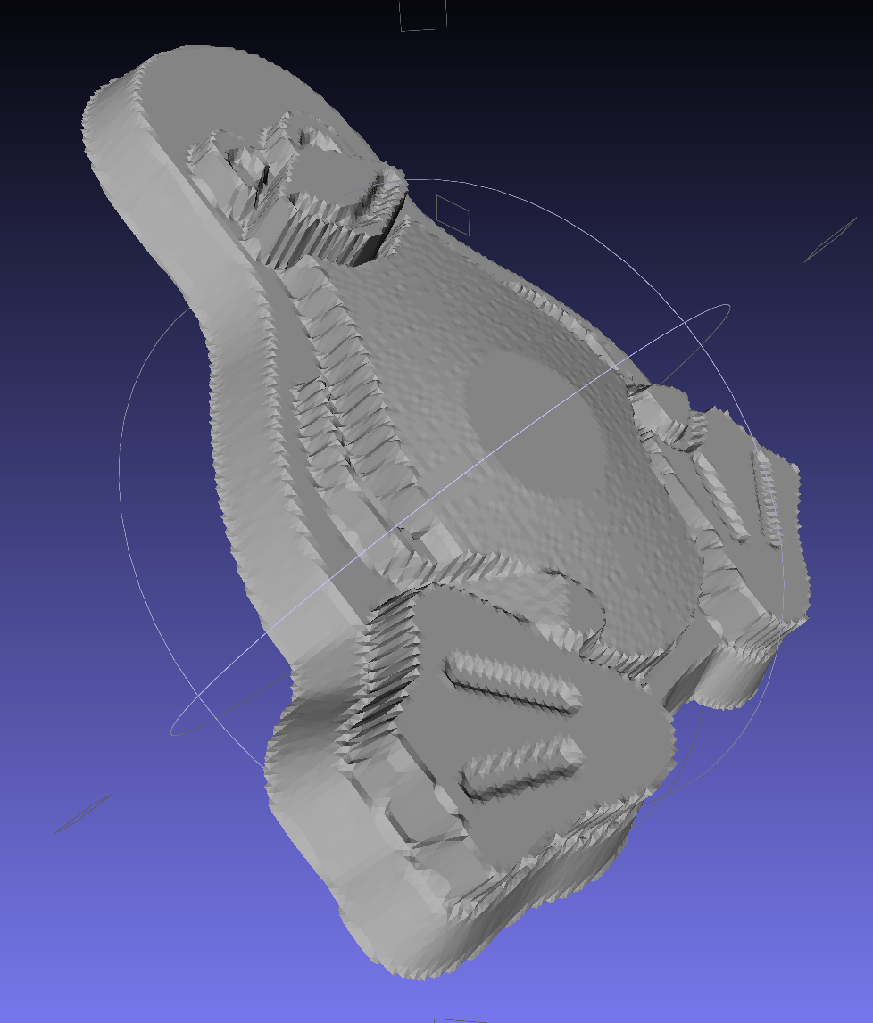
The corresponding silicone negative cavity, flipped top-to-bottom:
Tux Gradient – silicone negative detail
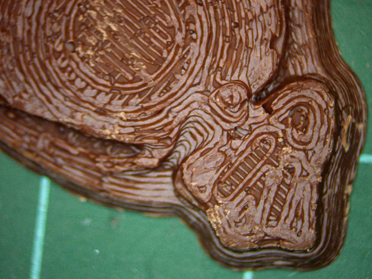
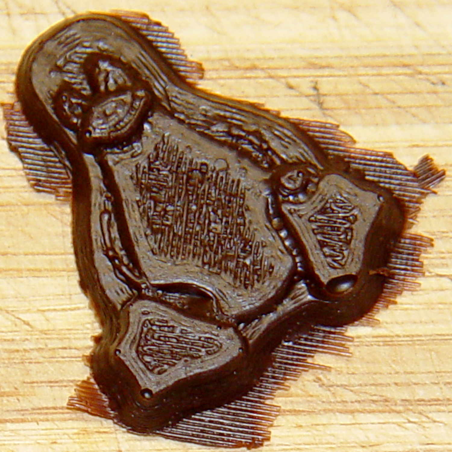
The milk chocolate result, although probably not from the same cavity:
Tux Gradient – milk chocolate detail
The radial gradient on the tummy comes through clearly and, I think, pleasingly, even though it’s only a few layers tall. The threads defining the flipper just above (to the left, in these images) of the foot show where the flipper crosses the tummy and foot level. I didn’t expect the foot webbing grooves to get that ladder-like texture, but I suppose having non-slip foot treads would be an advantage.
If you don’t mind the hand-knitted texture, which I don’t, this process seems perfectly workable.
Although directly printing the 2×2 molds worked reasonably well, that does not scale to larger arrays, because OpenSCAD doesn’t handle the profusion of vertices with any grace. Duplicating the STL file created from the height map image, however, isn’t a problem:
Tux-Gradient – Slic3r layout
I actually did it in two passes: 4 molds to be sure they’d come out right, then another dozen. Figure a bit under two hours for the lot of them, no matter how you, ah, slice it.
A grid drawn directly on 1/16 inch = 1.5 mm acrylic sheet guided the layout:
Tux Gradient 4×4 – mold as-cast
I anointed the back of each mold positive with PVC pipe cement, the version with tetrahydrofuran to attack the PLA and acetone/MEK to attack the acrylic, lined it up, and pressed it in place. The positives have recesses for alignment pins, but even I think that’s overkill in this application.
Memo to Self: Flip the acrylic over before gluing, so the guide lines wipe neatly off the bottom.
Tape a cardboard frame around the acrylic, mix & pour the silicone, put it on the floor to ensure it’s level (unlike our kitchen table), wait overnight for the cure, then peel positive and negative apart:
Tux Gradient 4×4 – mold separated
As before, the top surface of the positives isn’t watertight, so the silicone flowed through into the molds. This isn’t a simple extruder calibration issue, because the thinwall boxes are spot on, all the exterior dimensions are accurate, and everything else seems OK. What’s not OK is that threads on the top and (now that I look at it) bottom surfaces aren’t properly joining.
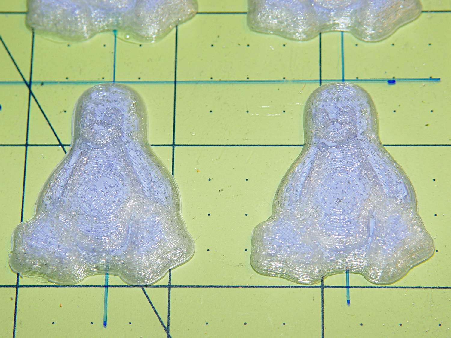
A closeup of the positive shows silicone between the threads and under the surface:
Tux Gradient 4×4 – postive detail
But the negative silicone looks just fine, in the usual hand-knitted way of all 3D printed parts:
Tux Gradient 4×4 – negative detail
Definitely fewer bubbles than before, although the flange between the flippers (wings? whatever) and the body isn’t as clean as it could be. Doing better may require pulling a vacuum on the silicone, which would mean the positives really must be air-tight solids.
Anyhow, the acrylic base produced a wonderfully flat surface that should make it a lot easier to run a scraper across the chocolate to remove the excess. Not that excess chocolate is ever a problem, but it’s the principle of the thing.
This is the simple height-map Tux image I’d been using for the chocolate molds:
Tux_Hi_Profile
But the poor critter looks a bit flattened:
Tux_Hi_Profile – solid model
The final result is tastier, but gives off a roadkill vibe:
Tux chocolates – detail
After a few tweaks to the image, now he has a radial gradient on his tummy, his right flipper extends forward, his feet have webs, and his smile looks radiant. The gray levels now extend over a larger range with a bit more separation, with the intent that he’ll now be 5 mm thick:
The game plan: drop a small object through a laser beam that shines on a photodiode, thus causing an electrical signal that triggers various flashes and cameras and so forth and so on. This fixture holds the laser and photodiode in the proper orientation, with enough stability that you (well, I) can worry about other things:
Laser-photodiode fixture – on blade
It’s mounted on the blade of a dirt-cheap 2 foot machinist’s square clamped to the bench which will probably get a few holes drilled in its baseplate for more permanent mounting.
The solid model looks about like you’d expect:
Laser-photodiode fixture – solid model
There’s a small hole in the back for an 8-32 setscrew that locks it to the blade; the fit turned out snug enough to render the screw superfluous. I added those two square blocks with the holes after I taped the wires to the one in the picture.
The two semicircular (well, half-octagonal) trenches have slightly different diameters to suit the heatshrink tubing around the photodiode (a.k.a., IR LED) and brass laser housing. A dab of fabric adhesive holds the tubes in place, in addition to the Gorilla Tape on the ends.
The laser came focused at infinity, of course. Unscrewing the lens almost all the way put the focus about 3/4 of the way across the ring; call it 40 mm. The beam is rectangular, about 1×2 mm, at the center of the ring, and I rotated the body to make the short axis vertical; that’s good enough for my purposes.
The cable came from a pair of cheap earbuds with separate Left/Right pairs all the way from the plug.
The model builds in one piece, of course, and pops off the platform ready to use:
Laser-photodiode fixture – on platform
If you were doing this for an analytic project, you’d want a marker for the beam centerline on the vertical scale, but that’s in the nature of fine tuning. As it stands, the beam sits 8 mm above the base and flush with the top surface of the ring; if that were 10 mm, it’d be easier to remember.
The OpenSCAD source code has a few tweaks and improvements:
// Laser and LED-photodiode break-beam sensor
// Ed Nisley - KE4ZNU - March 2014

Layout = "Show";			// Build Show Ring Mount Guide

//- Extrusion parameters must match reality!
//  Print with 2 shells and 3 solid layers

ThreadThick = 0.20;
ThreadWidth = 0.40;

HoleWindage = 0.2;			// extra clearance

Protrusion = 0.1;			// make holes end cleanly

AlignPinOD = 1.70;			// assembly alignment pins: filament dia

inch = 25.4;

function IntegerMultiple(Size,Unit) = Unit * ceil(Size / Unit);

//----------------------
// Dimensions

LaserOD = 6.0;				// brass focus tube
LaserLength = 20.0;			//  ... wire clearance

SensorOD = 6.5;				// including light shield
SensorLength = 20.0;		//  ... wire clearance

RingSize = [50.0,70.0,8.0,8*4];	// support ring dimensions
RING_ID = 0;
RING_OD = 1;
RING_THICK = 2;
RING_SIDES = 3;

StrutWidth = 2.5;					// strut supporting this thing
StrutLength = 26.5;

StrutBlock = [10.0,35.0,20.0];		// block around the clearance slot
BLOCK_WIDTH = 0;
BLOCK_LENGTH = 1;
BLOCK_HEIGHT = 2;

StrutScrewTap = 2.7;				// 6-32 SHCS

GuideID = 4.0;						// guide for cables
GuideOD = 3*GuideID;

BuildSpace = 3.0;					// spacing between objects on platform

//----------------------
// Useful routines

module PolyCyl(Dia,Height,ForceSides=0) {			// based on nophead's polyholes

  Sides = (ForceSides != 0) ? ForceSides : (ceil(Dia) + 2);

  FixDia = Dia / cos(180/Sides);

  cylinder(r=(FixDia + HoleWindage)/2,
           h=Height,
           $fn=Sides);
}

module ShowPegGrid(Space = 10.0,Size = 1.0) {

  RangeX = floor(100 / Space);
  RangeY = floor(125 / Space);

	for (x=[-RangeX:RangeX])
	  for (y=[-RangeY:RangeY])
		translate([x*Space,y*Space,Size/2])
		  %cube(Size,center=true);

}

module Ring() {

	difference() {
		union() {
			rotate(180/RingSize[RING_SIDES])
				cylinder(d=RingSize[RING_OD],h=RingSize[RING_THICK],
						$fn=RingSize[RING_SIDES]);
			translate([-LaserOD,(-LaserLength - RingSize[RING_ID]/2),0])
				cube([2*LaserOD,LaserLength,RingSize[RING_THICK]],center=false);
			translate([-SensorOD,(-0*SensorLength + RingSize[RING_ID]/2),0])
				cube([2*SensorOD,SensorLength,RingSize[RING_THICK]],center=false);
		}
		rotate(180/RingSize[RING_SIDES])
			translate([0,0,-Protrusion])
				cylinder(d=RingSize[RING_ID],h=(RingSize[RING_THICK] + 2*Protrusion),
						$fn=RingSize[RING_SIDES]);
		translate([0,0,RingSize[RING_THICK]])
			rotate([90,0,0]) rotate(180/8)
				PolyCyl(LaserOD,3*LaserLength,8);
		translate([0,0,RingSize[RING_THICK]])
			rotate([-90,0,0]) rotate(180/8)
				PolyCyl(SensorOD,3*SensorLength,8);
	}
}

module Mount() {
	translate([0,0,StrutBlock[2]/2])
		difference() {
			cube(StrutBlock,center=true);
			cube([StrutWidth,StrutLength,2*StrutBlock[2]],center=true);
			translate([0,-StrutLength/3,0])
				rotate([90,0,0])
					PolyCyl(StrutScrewTap,StrutLength/2,6);
		}
}

module Guide() {

	difference() {
		translate([0,0,RingSize[RING_THICK]/2])
			cube([GuideOD,GuideOD,RingSize[RING_THICK]],center=true);
		translate([0,0,-Protrusion]) rotate(180/8)
			PolyCyl(GuideID,(RingSize[RING_THICK] + 2*Protrusion),8);
	}
}

module Assembly() {
	Ring();
	translate([(RingSize[RING_OD]/2 + StrutBlock[BLOCK_LENGTH]/2
				- (StrutBlock[BLOCK_LENGTH] - StrutLength)/2) + Protrusion,0,0])
		rotate(90)
			Mount();
	for (i=[-1,1])
		translate([(RingSize[RING_OD]/2 + GuideID/2),
				  i*(StrutBlock[BLOCK_WIDTH]/2 + GuideID),
				  0])
			Guide();
}

//- Build it

ShowPegGrid();

if (Layout == "Ring") {
	Ring();
}

if (Layout == "Mount") {
	Mount();
}

if (Layout == "Guide") {
	Guide();
}

if (Layout == "Show") {
	Assembly();
}

if (Layout == "Build") {

	translate([-5/2,-5/2,0])
		cube(5);
}