Ed Nisley's Blog: Shop notes, electronics, firmware, machinery, 3D printing, laser cuttery, and curiosities. Contents: 100% human thinking, 0% AI slop.
Back when I started fiddling with 3D printed chain mail, the whole process from model to plastic worked wonderfully well. That continued with the larger sheets, but now, occasionally, the OpenSCAD model would produce weirdly sliced links. Depending on nothing repeatable, some links wouldn’t bridge correctly: the thread paths in the bottom layer across the gap would mysteriously stop just short of one pillar, return to the start, and leave an unsupported shelf that would, of course, fall into the gap.
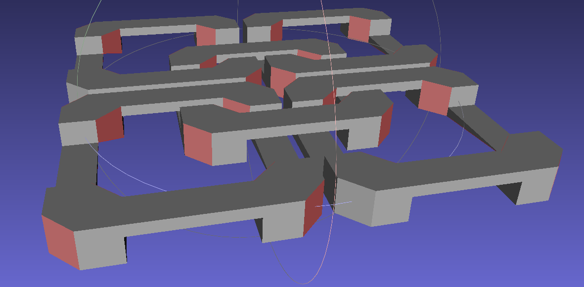
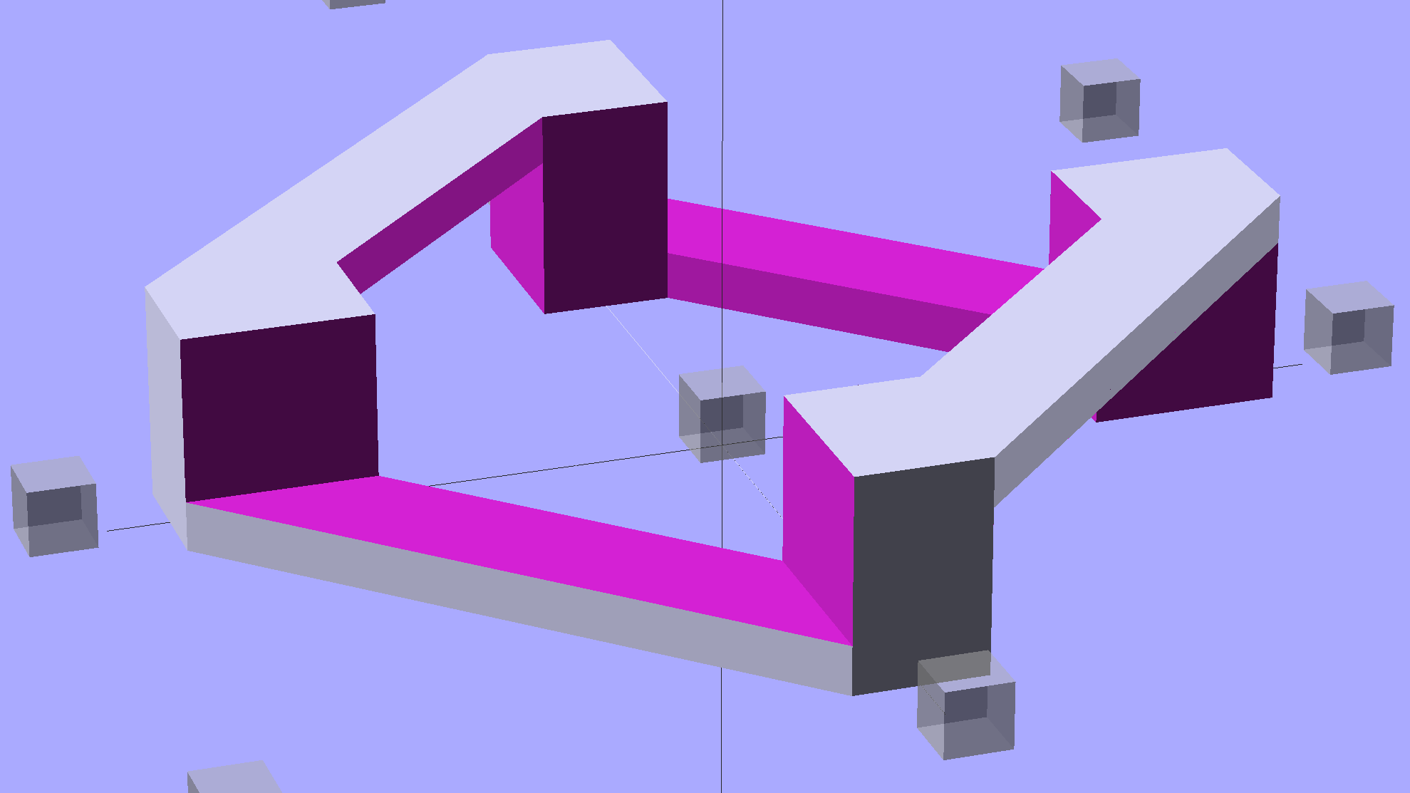
Shortly before Christmas, I managed to get a consistent failure that manifested differently: upon loading the STL file, Slic3r would quietly perform dozens of automatic corrections that (sometimes!) produced bizarrely distorted results. Feeding a failing model into Meshlab showed an irregular assortment of “self intersecting faces”, highlighted in red:
Chain Mail Square Armor – open – 2×2 – Meshlab self-intersecting faces
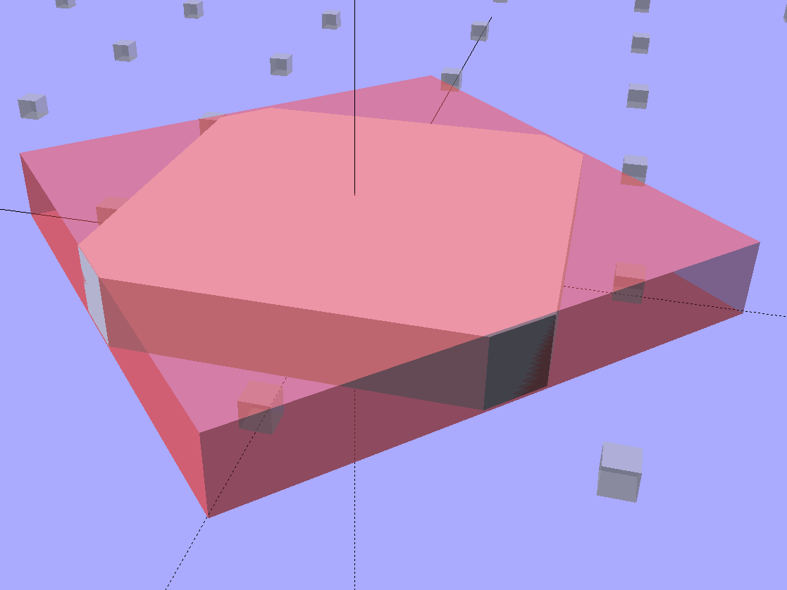
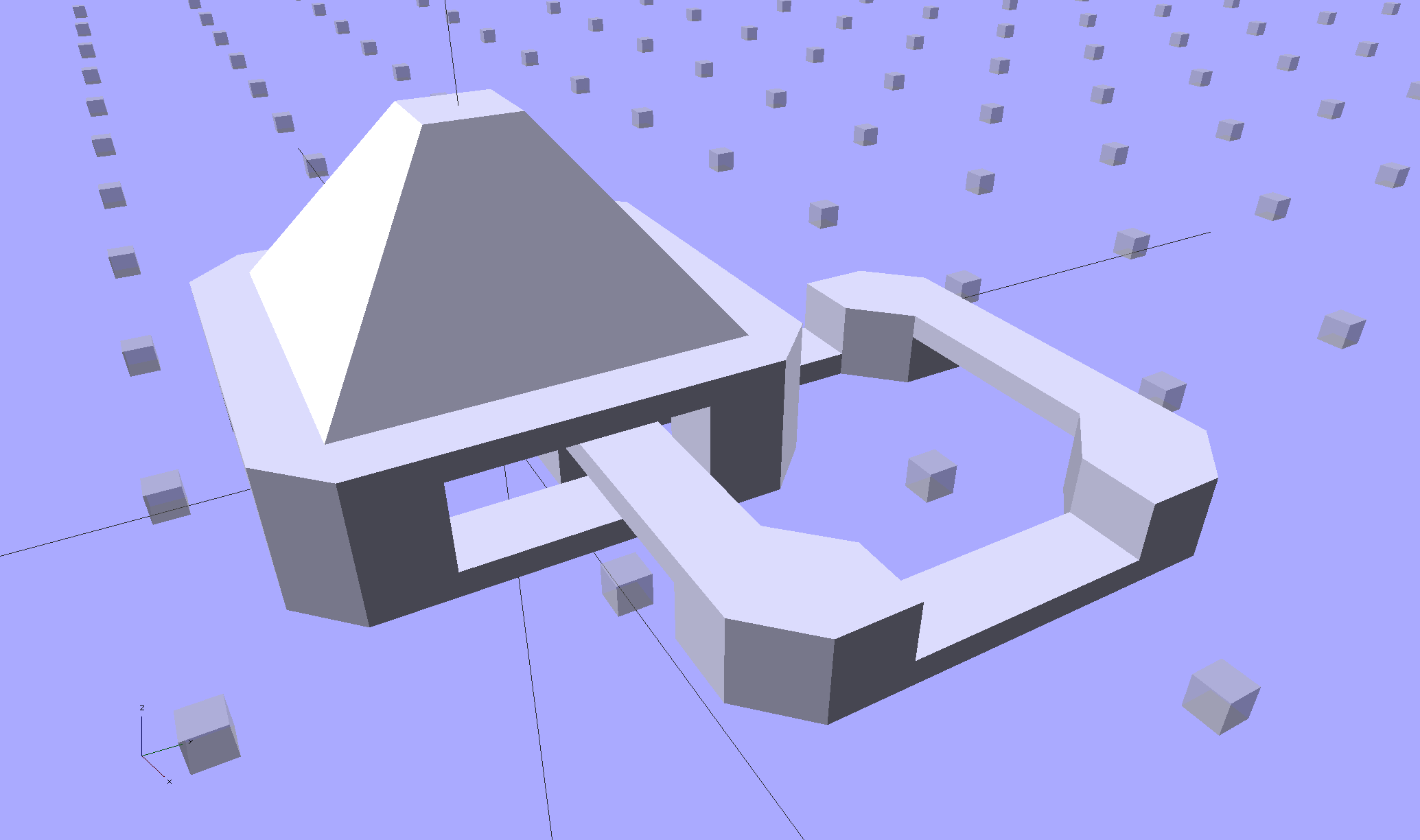
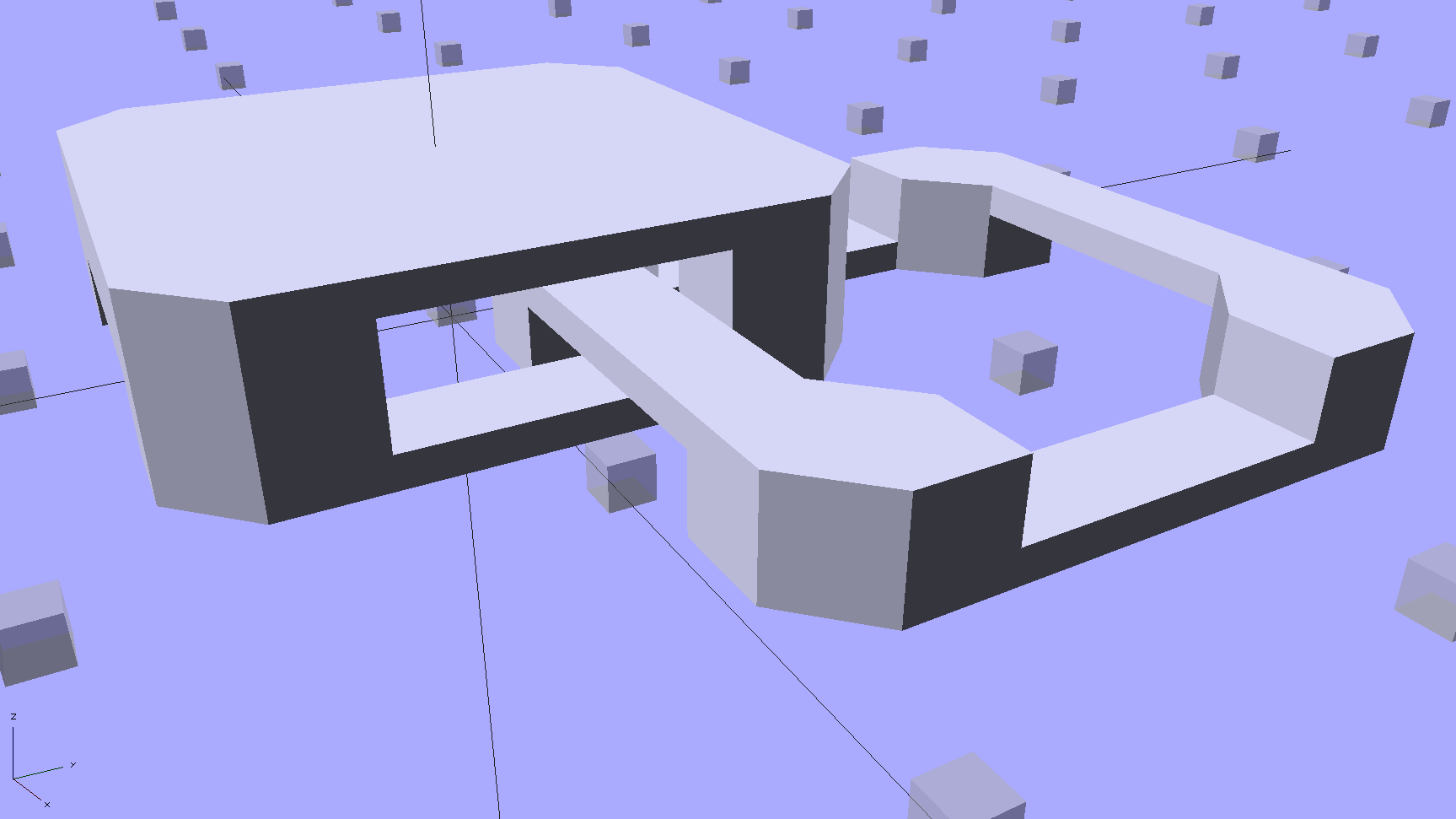
Although all four outer links in that image come from the same OpenSCAD module with identical sizes, they don’t all exhibit the same problem in the (nominally identical) faces on each of their four corners. In fact, those faces come from the intersection of two square slabs, carefully sized and positioned to avoid creating coincident planes:
Chain Mail Link – Outer shape
The central opening comes from a similar, slightly smaller, intersected-squares shape, but all four interior corner faces in each link show that they’re self-intersecting.
The STL looked fine in Meshlab, except for the highlit self-intersecting faces, so the geometry seemed OK.
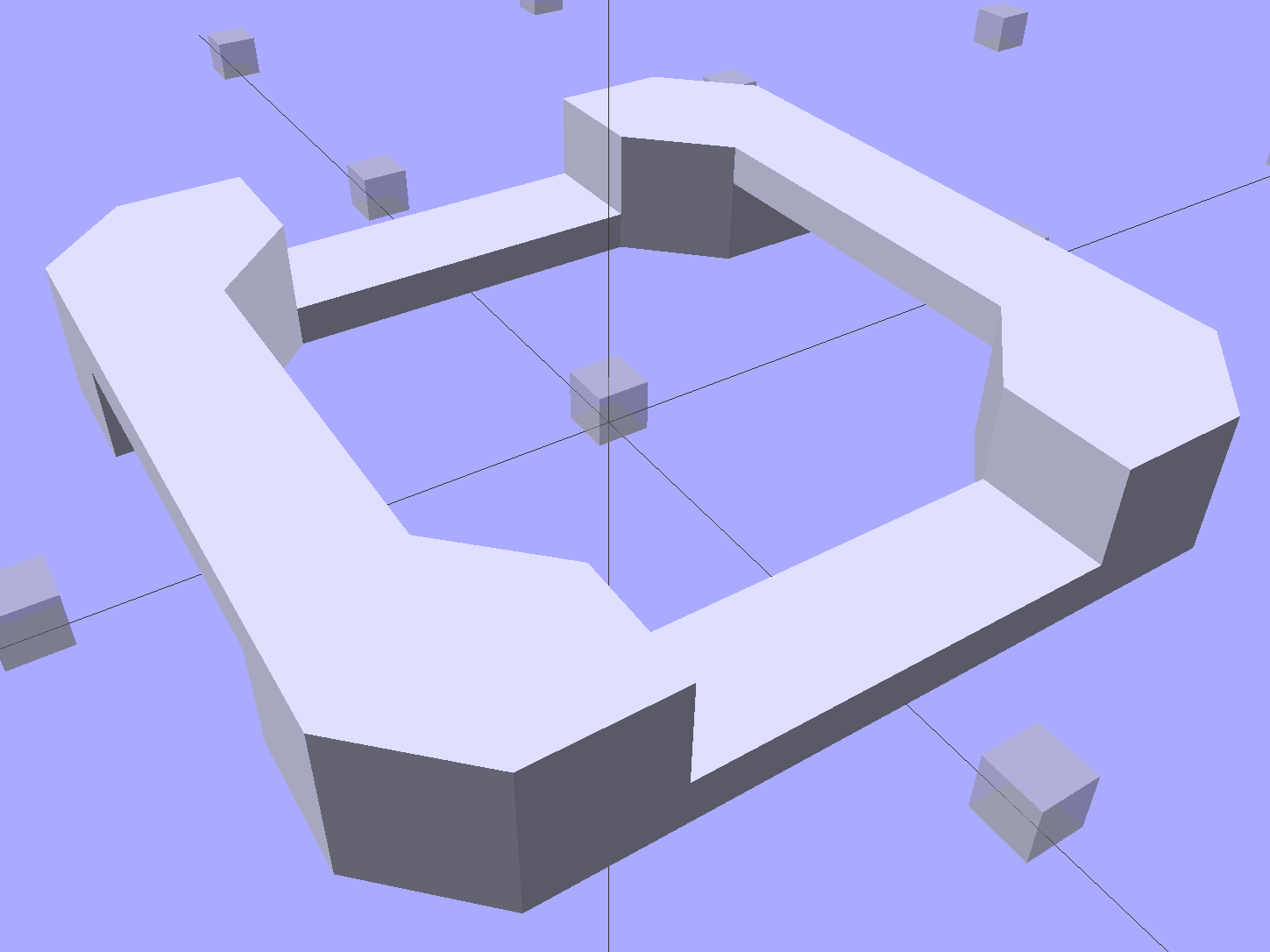
When Slic3r autocorrected the “problems”, it apparently removed one vertex on the bottom surface of each bar, deleted the triangles connected to that vertex, then repaired the mesh to produce a delightfully symmetric pattern:
Chain Mail Square Armor – open – 2×2 – Slic3r corrections
Although the links are resolutely symmetric, Slic3r seemed happy with the identical vertices at the other end of the bar.
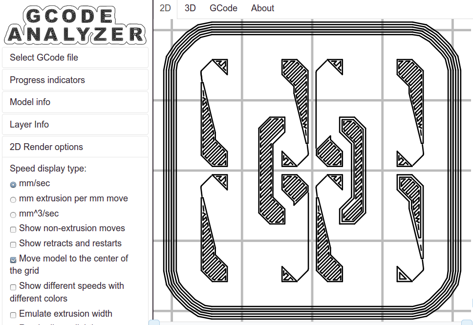
Unfortunately, the resulting G-Code won’t produce good links:
Chain Mail Square Armor – open – 2×2 – first layer G-code visualization
So, shortly before Christmas, I filed an issue on OpenSCAD’s Github repository.
The ensuing discussion showed that Meshlab flags faces as “self intersecting” when they have different vertices, even if their values are numerically equal, as well as vertices that differ by teeny amounts. Slic3r applies slightly different criteria to vertices & faces when it automagically corrects “problems” in the STL file, so that Meshlab may:
Highlight faces that don’t bother Slic3r
Apply the same highlight to faces that cause horrible problems
I don’t profess to understand much of that and may have the details wrong, but, apparently, OpenSCAD formerly used quantized coordinates that ensured all vertices within a tiny volume would have the same numeric value. In particular, all three faces that meet at a common point would, in fact, have numerically equal coordinate values for that point. The STL file format consists of a list of separate triangles, each with three coordinates for each of the three axes, and (without quantization) it was entirely possible for each of the three triangles with a common point to have three very slightly different positions for that point.
In theoretic terms, quantized coordinates cause horrible problems during geometric manipulation, because numeric values that aren’t exact can make repeated transformations come out wrong; running an object through a transformation and it’s inverse might not yield an object identical to the original one.
In practical terms, it seems that slicers and STL repair algorithms can reach incorrect conclusions based on minute differences produced by floating-point operations and numeric-to-text conversions. Those differences depend on slight changes in position, rotation, and size, so doing anything to the model produces completely different results.
That notwithstanding, the day after Christmas brought a new OpenSCAD version that uses quantized coordinates. A bit of rummaging in the source shows that the 3D grid (defined in src/grid.h) isn’t all that coarse:
const double GRID_FINE = 0.00000095367431640625;
STL files don’t carry units, so that could be in either millimeters (the Slic3r / RepRap convention) or inches (Sketchup, but we won’t go there). It’s exactly 1/10242, in case you were wondering, which produces a 5% speedup in the geometry engine compared to the more human-readable 1/10002.
With that commit in hand, all the chain mail links slice perfectly again.
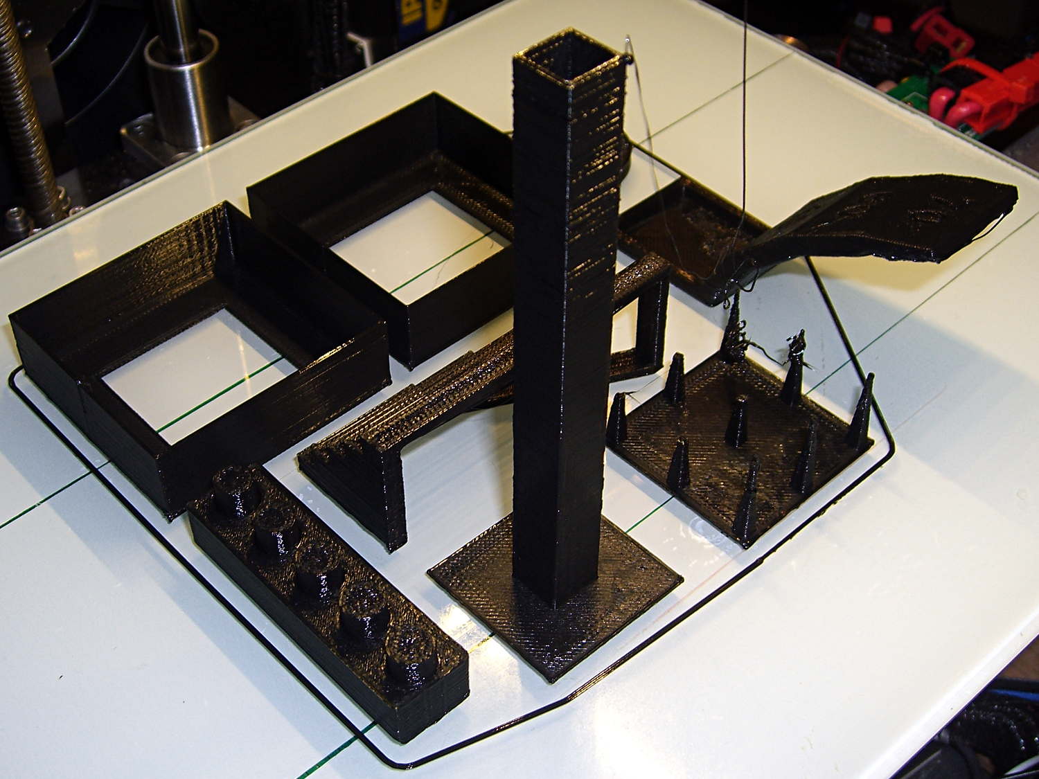
Just for completeness, here’s how the MAKE Magazine 2015 Test Objects came out on my somewhat modified MakerGear M2. I ignored the instructions, lumped all the models together, sliced ’em with my ordinary Slic3r settings, and printed the entire lot in one go:
MAKE Magazone 2015 Test Objects – on platform
Some details…
There’s no point in showing the Dimension Accuracy Tower-of-Hanoi (hiding behind the smokestack), as it looks exactly like it should. The 20 mm diameter platter came out at 19.7 ± 0.05 mm in both X and Y, so that’s a score of 2 or 3. It’s exactly the same along both axes, both diagonals, and, in fact, all the way around, within ±0.07 mm tolerance. In fact, all the layers worked out about that way; it’s consistently a bit too small. That’s what I’d expect for an uncalibrated model.
The Bridging Performance lattice gets a 5, with all the bars having dead-flat perimeters and no dropped infill. That would be a 1 if “dropped” should be “drooped”; I have no idea which is correct or exactly what they mean, but I have seen bridge threads drop off the sides, so I’ll assume it means what it says.
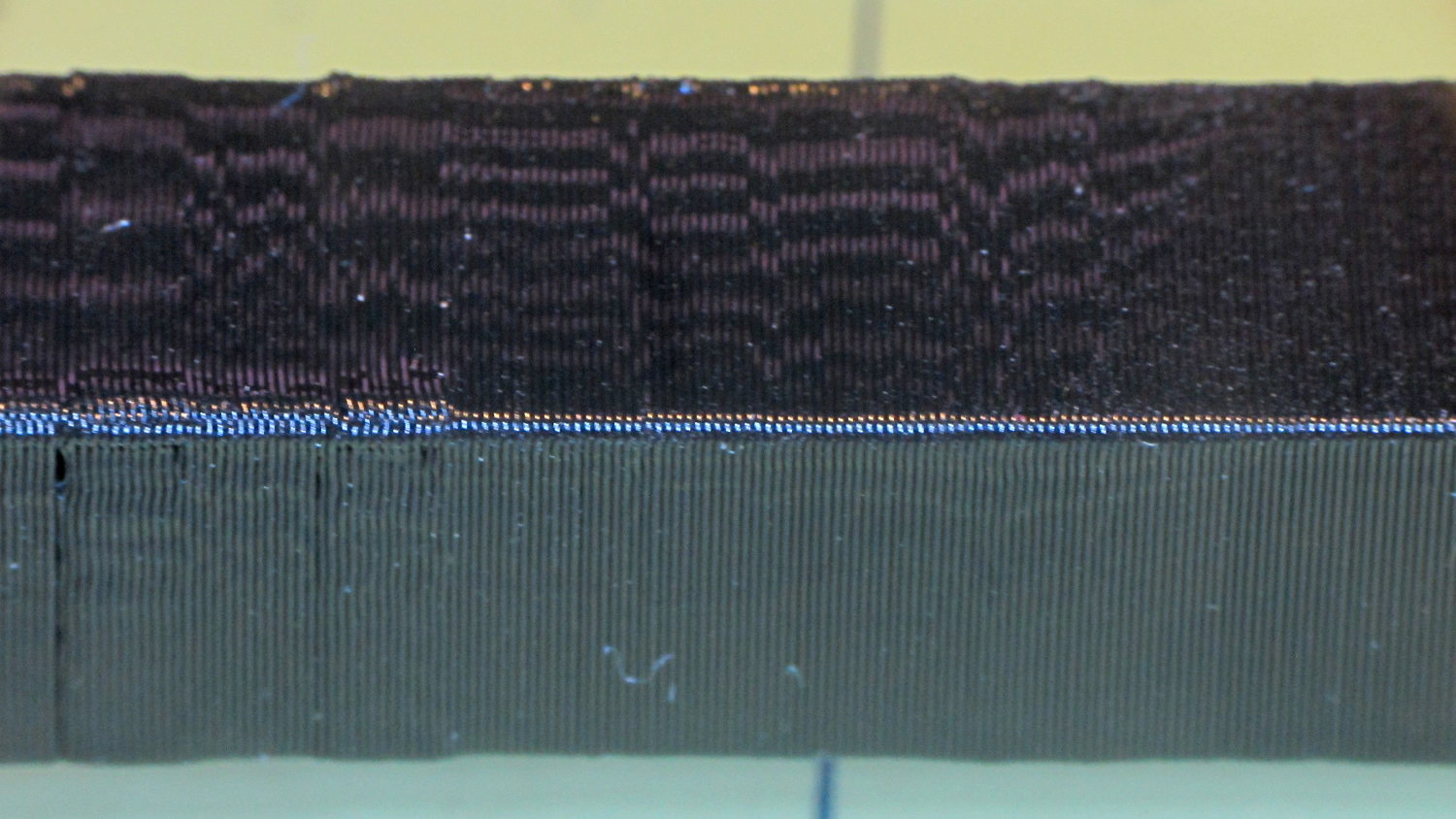
The front view shows the first bridging layer getting droopy under the longer bars, as you’d expect:
Bridging – front
All those drooping threads remain above the 2 mm tolerance, assuming that’s what they intended.
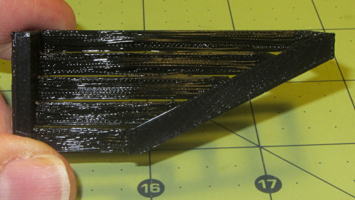
The bottom view shows the loose strands below the bars:
Bridging – bottom
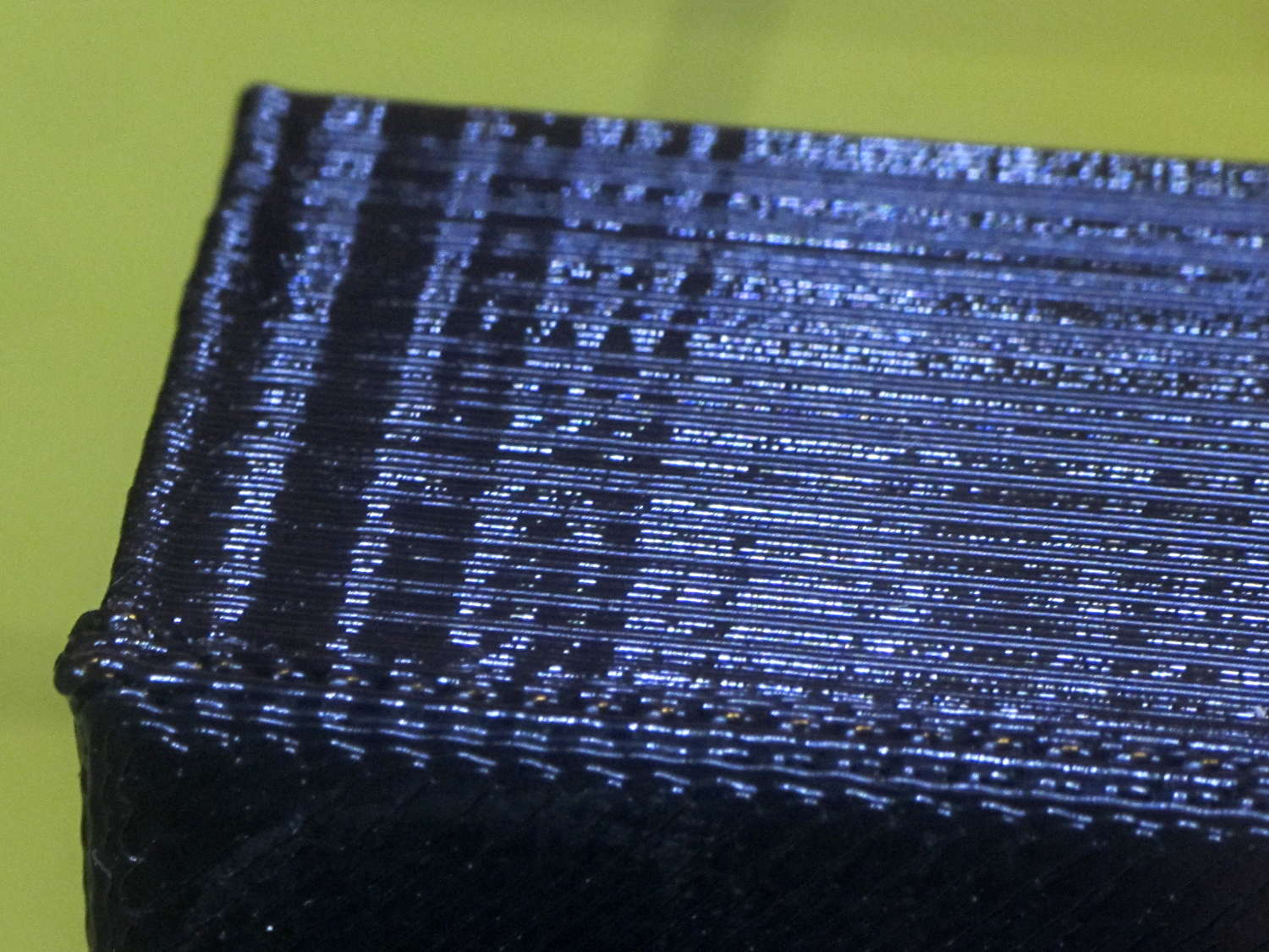
The Overhang Performance arch gets a 5, because the top surface finish remains pretty much the same from 30° through 70° overhang:
Overhang – upper
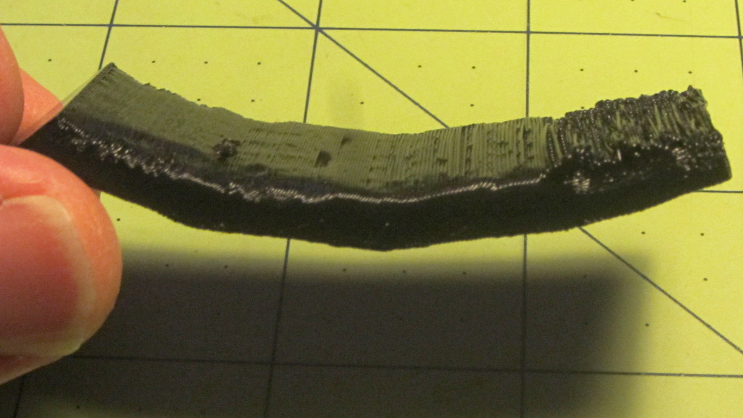
Underneath, things look weirder:
Overhang – lower
I think the oddness on the left (the underside of the 30° section) is due to interference from the Fine Positive Space Features spire array; the nozzle came directly from there. The 70° overhang looks ugly, but I wouldn’t have imagined that would work at all, let alone as well as it did.
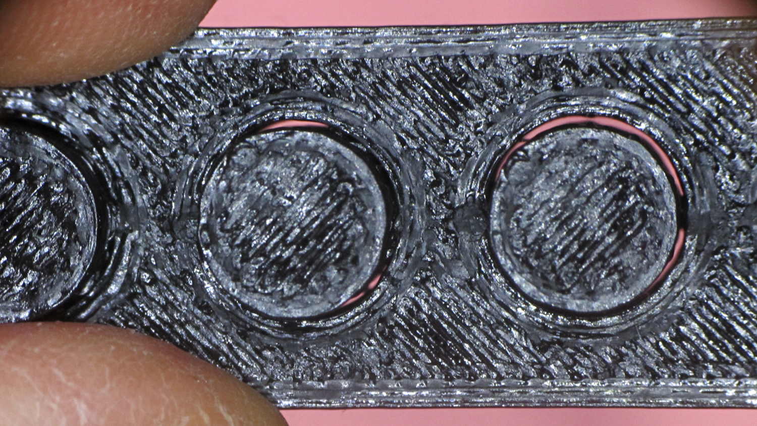
The Negative Space Tolerance block weighs in at 2, as the pins with 0.6 and 0.5 mm clearance pushed out with finger pressure. The 0.3 and 0.4 mm clearance pins have air nearly all the way around, but would require a sharp rap from a mallet. The 0.2 mm pin remains firmly stuck:
Negative Space Tolerance
I don’t know how to judge the Fine Positive Space Features bed-o’-nails:
Fine Positive
I think it’s either a 2 or a 3, but opinions will certainly differ. Hot off the platform, five of the nine spires completed successfully. Three other got almost done, but broke off in handling. The collection of drool on the left-middle spire seems to be from the uncompleted spires in the foreground; I think there just wasn’t enough adhesion to hold them together. The perimeters ran at 50 mm/s and the infill at 150 mm/s, because it’s printed with everything else, so it wasn’t done with the delicacy it would get in isolation.
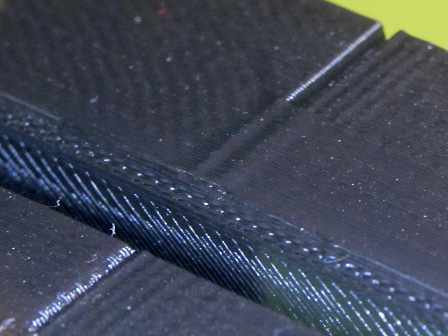
Both Mechanical Resonance in XY boxes look fine to me:
XY Resonance – notch
The ripples are visible, but barely perceptible to the thumbnail. The Rules call for 0 or 2, I’d give it a 1: if those ripples pose a problem, then sheesh you’re using the wrong process.
Also, the perimeters ran at 50 mm/s perimeter and the thick walls got 150 mm/s infill.
A corner of the single-wall box looks about the same as the corresponding point on the 1 mm box (which isn’t shown):
XY Resonance – corner
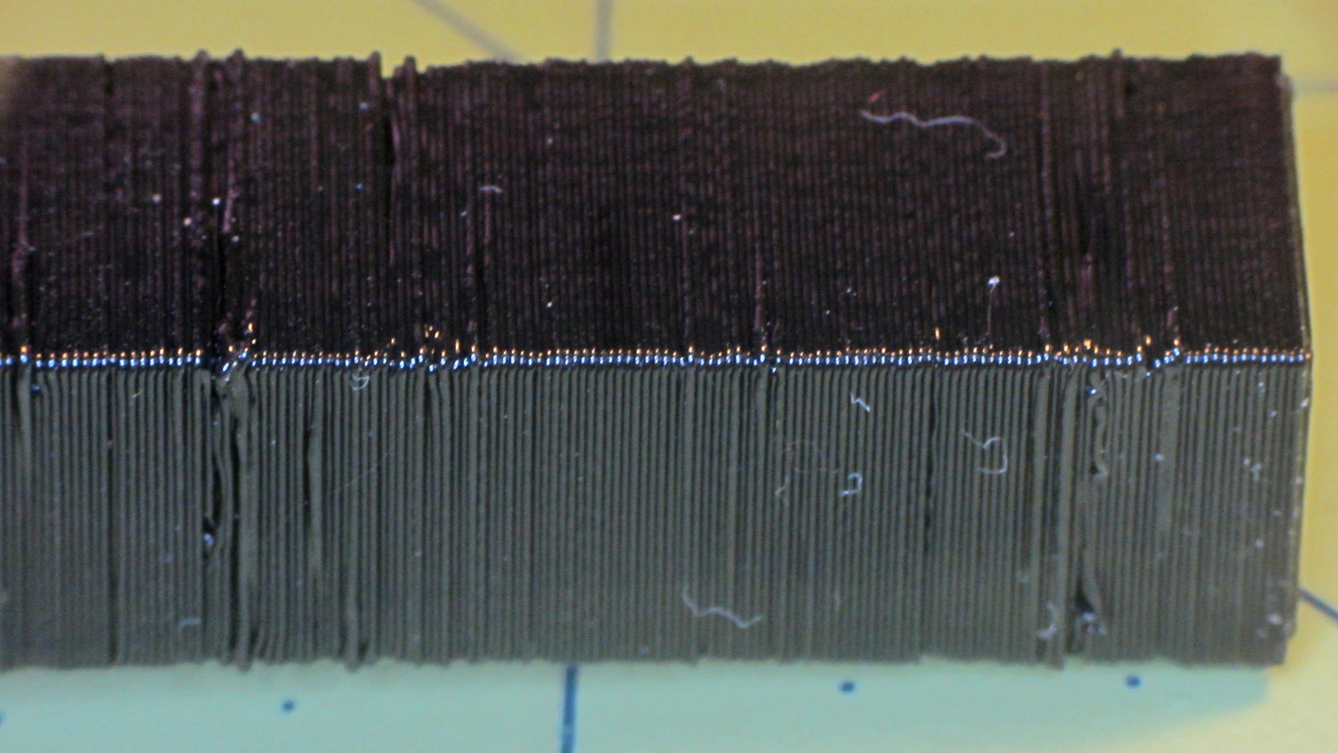
I think the Mechanical Resonance in Z smokestack gets a 1 (the Rules allow either 0 or 2); I stopped it after 100 mm, because bedtime. The bottom section shows the influence of all the other stuff going on around it:
Z Resonance – lower
That’s not a missed step over there on the far left: it lines up with the bottom bar of the adjacent Bridging Performance lattice. The next glitch lines up with the top of the Negative Space block. And so forth and so on.
The top, done all by itself at 11 mm/s, shows some misalignment:
Z Resonance – upper
Each layer took 15 seconds, so I suspect it’d look better with more cooling.
So, using ordinary default settings for everything and with all the handwaving in mind, I’ll call the total score 19-ish of a possible 29. The M2 would definitely do better on individual objects sliced with carefully hand-tuned parameters after considerable iteration; this is its ordinary, day-in-and-day-out performance on crazy models that I’d never attempt without tweaking.
The score would be much much much higher if I judged it with criteria similar to what I see applied to some of the Thingiverse groupings.
The M2 works well for me, anyhow.
For reference, here’s the current Slic3r configuration:
# generated by Slic3r 1.2.1 on Sun Dec 7 12:19:19 2014
avoid_crossing_perimeters = 0
bed_shape = -100x-125,100x-125,100x125,-100x125
bed_temperature = 70
bottom_solid_layers = 3
bridge_acceleration = 0
bridge_fan_speed = 100
bridge_flow_ratio = 1
bridge_speed = 150
brim_width = 0
complete_objects = 0
cooling = 1
default_acceleration = 0
disable_fan_first_layers = 1
dont_support_bridges = 1
duplicate_distance = 6
end_gcode = ;-- Slic3r End G-Code for M2 starts --\n; Ed Nisley KE4NZU - 15 November 2013\nM104 S0 ; drop extruder temperature\nM140 S0 ; drop bed temperature\nM106 S0 ; bed fan off\nG1 Z160 F2000 ; lower bed\nG1 X130 Y125 F30000 ; nozzle to right, bed front\nM84 ; disable motors\n;-- Slic3r End G-Code ends --
external_perimeter_extrusion_width = 0
external_perimeter_speed = 50
external_perimeters_first = 0
extra_perimeters = 1
extruder_clearance_height = 25
extruder_clearance_radius = 15
extruder_offset = 0x0
extrusion_axis = E
extrusion_multiplier = 1.07
extrusion_width = 0.4
fan_always_on = 0
fan_below_layer_time = 30
filament_diameter = 1.72
fill_angle = 45
fill_density = 20%
fill_pattern = 3dhoneycomb
first_layer_acceleration = 0
first_layer_bed_temperature = 70
first_layer_extrusion_width = 0.4
first_layer_height = 100%
first_layer_speed = 25
first_layer_temperature = 175
gap_fill_speed = 50
gcode_arcs = 0
gcode_comments = 0
gcode_flavor = reprap
infill_acceleration = 0
infill_every_layers = 2
infill_extruder = 1
infill_extrusion_width = 0
infill_first = 1
infill_only_where_needed = 0
infill_speed = 150
interface_shells = 0
layer_gcode =
layer_height = 0.2
max_fan_speed = 100
min_fan_speed = 75
min_print_speed = 4
min_skirt_length = 15
notes =
nozzle_diameter = 0.35
only_retract_when_crossing_perimeters = 1
ooze_prevention = 0
output_filename_format = [input_filename_base].gcode
overhangs = 1
perimeter_acceleration = 0
perimeter_extruder = 1
perimeter_extrusion_width = 0.4
perimeter_speed = 150
perimeters = 2
post_process =
raft_layers = 0
resolution = 0.01
retract_before_travel = 1
retract_layer_change = 0
retract_length = 1
retract_length_toolchange = 5
retract_lift = 0
retract_restart_extra = 0
retract_restart_extra_toolchange = 0
retract_speed = 60
seam_position = nearest
skirt_distance = 3
skirt_height = 1
skirts = 3
slowdown_below_layer_time = 10
small_perimeter_speed = 50
solid_fill_pattern = rectilinear
solid_infill_below_area = 5
solid_infill_every_layers = 0
solid_infill_extrusion_width = 0
solid_infill_speed = 150
spiral_vase = 0
standby_temperature_delta = -5
start_gcode = ;-- Slic3r Start G-Code for M2 starts --\n; Ed Nisley KE4NZU - 15 Nov 2013\n; 28 Feb 2014 - 6 Mar 2014 - tweak Z offset June July 2014\n; Z-min switch at platform, must move nozzle to X=130 to clear\nM140 S[first_layer_bed_temperature] ; start bed heating\nG90 ; absolute coordinates\nG21 ; millimeters\nM83 ; relative extrusion distance\nG92 Z0 ; set Z to zero, wherever it might be now\nG1 Z10 F1000 ; move platform downward to clear nozzle; may crash at bottom\nG28 Y0 ; home Y to be sure of clearing probe point\nG92 Y-127 ; set origin so 0 = center of plate\nG28 X0 ; home X\nG92 X-95 ; set origin so 0 = center of plate\nG1 X130 Y0 F30000 ; move off platform to right side, center Y\nG28 Z0 ; home Z with switch near center of platform\nG92 Z-4.65 ; set origin to measured z offset\nG0 Z2.0 ; get air under switch\nG0 Y-127 F10000 ; set up for priming, zig around corner\nG0 X0 ; center X\nM109 S[first_layer_temperature] ; set extruder temperature and wait\nM190 S[first_layer_bed_temperature] ; wait for bed to finish heating\nG1 Z0.0 F500 ; put extruder at plate \nG1 E30 F300 ; prime to get pressure, generate blob\nG1 Z5 F2000 ; rise above blob\nG1 X15 Y-125 F20000 ; jerk away from blob, move over surface\nG1 Z0.0 F1000 ; dab nozzle to attach outer snot to platform\nG4 P0.5 ; pause to attach\nG1 X35 F500 ; slowly smear snot to clear nozzle\nG1 Z1.0 F2000 ; clear bed for travel\n;-- Slic3r Start G-Code ends --
support_material = 0
support_material_angle = 0
support_material_enforce_layers = 0
support_material_extruder = 1
support_material_extrusion_width = 0
support_material_interface_extruder = 1
support_material_interface_layers = 3
support_material_interface_spacing = 0
support_material_interface_speed = 100%
support_material_pattern = pillars
support_material_spacing = 2.5
support_material_speed = 150
support_material_threshold = 0
temperature = 175
thin_walls = 1
threads = 2
toolchange_gcode =
top_infill_extrusion_width = 0
top_solid_infill_speed = 50
top_solid_layers = 3
travel_speed = 250
use_firmware_retraction = 0
use_relative_e_distances = 0
vibration_limit = 0
wipe = 0
xy_size_compensation = 0
z_offset = 0
Another nine hours of printing produced a second 9×13 link chain mail armor sheet that simply begged to be joined with the first. Snipping a connecting link on one sheet and attempting to thread it through the armor button on the other didn’t work nearly as well as I expected, because the pillars on the open links don’t quite pass through the slot in the side of the armor button links:
Chain Mail Armor – 4 sided
So I summoned joiner links from the digital deep:
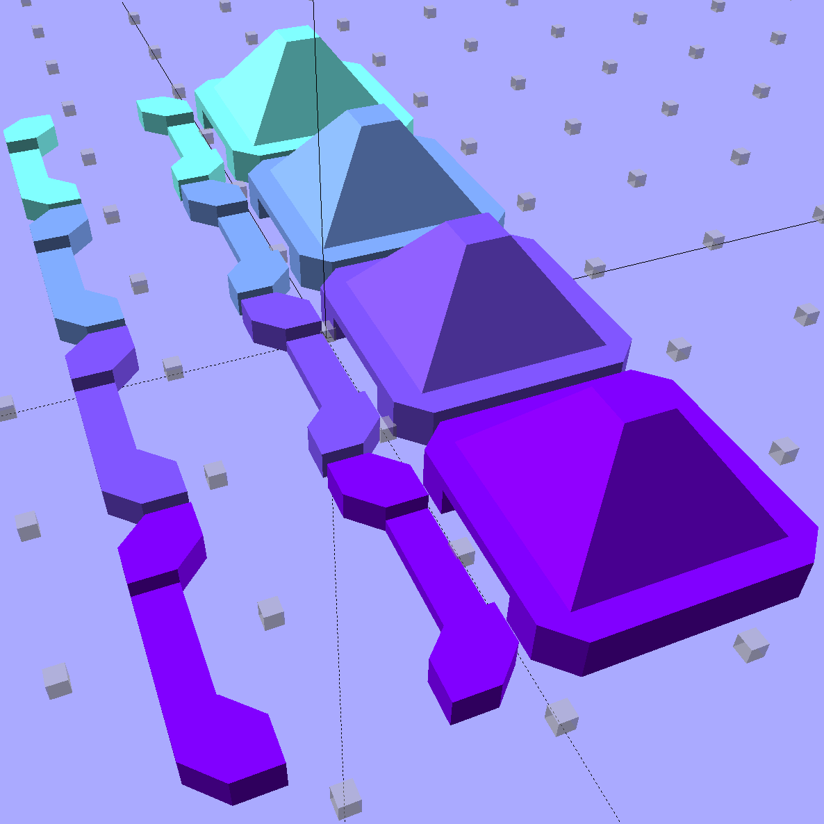
Chain Mail Armor – Sheet Joiners
Those are standard armor button links, split at the cross bar level, then laid out along the Y axis. The cap bridges across the link just as it does on the chain mail sheets, so, when they’re glued back together, the result should be exactly like a solid link. There’s no room for alignment pins and, frankly, I wouldn’t fiddle with two dozen filament snippets anyway.
The OpenSCAD code below produces joiners that work for the square arrangement, not the diamond, but that’s in the nature of fine tuning.
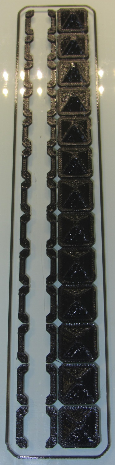
When I saw them pasted to the platform, just like the model:
Chain Mail Armor – joiners on platform
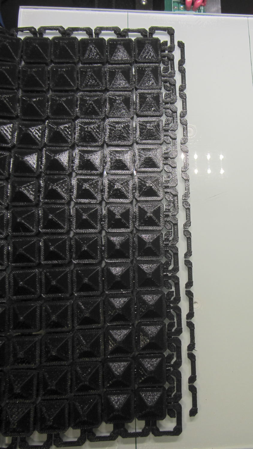
It occurred to me that I could pop the caps off, then lay the sheets in position, aligned on the underlying joiner half-links. Here’s the first sheet over the left set of bars:
Chain Mail Armor – sheet and joiners on platform
Then glue the armor caps in place:
Chain Mail Armor – joiner with solvent glue
Four dots of IPS #4 solvent glue, dispensed from a fine copper tube serving as a pipette, wet the four pillars of the joiner’s two bottom bars. I dotted each pillar to begin softening the PLA, paused for a breath, wet them again to leave enough solvent to bite into the bottom of the armor cap, pressed the cap in place, tweaked the alignment with tweezers, then pressed downward for maybe five seconds. Although the joiner link has no inherent alignment features, there’s also not much room to slide around and it worked surprisingly well.
Repeat that trick dozen times and you’re done. The aggravation scales as the square root of the overall sheet size, so it’s not as awful as assembling every single link, but it’s definitely a task for the low-caffeine part of the day.
One bottom bar came loose when I showed the result at the MHVLUG meeting, but the bar reappeared and I glued it again easily enough. I’ve now printed several spare joiners, Just In Case.
The bottom bars aren’t firmly affixed to the platform after it cools and they dislodge fairly easily: that’s how I get larger models off: let everything cool, then simply lift the plastic off. If I were joining sheets on a regular basis, I’d conjure a fixture to hold the sheets and joiner caps in position, probably with the sheets upside down, then glue the bars atop the inverted caps. That could get messy.
Perhaps a special holder to capture the bars in the proper alignment, maybe with pins matching the square openings at the corners, would help?
This is a trial fit before gluing that’s visually indistinguishable from the final product:
Chain Mail Armor – joined sheets on platform
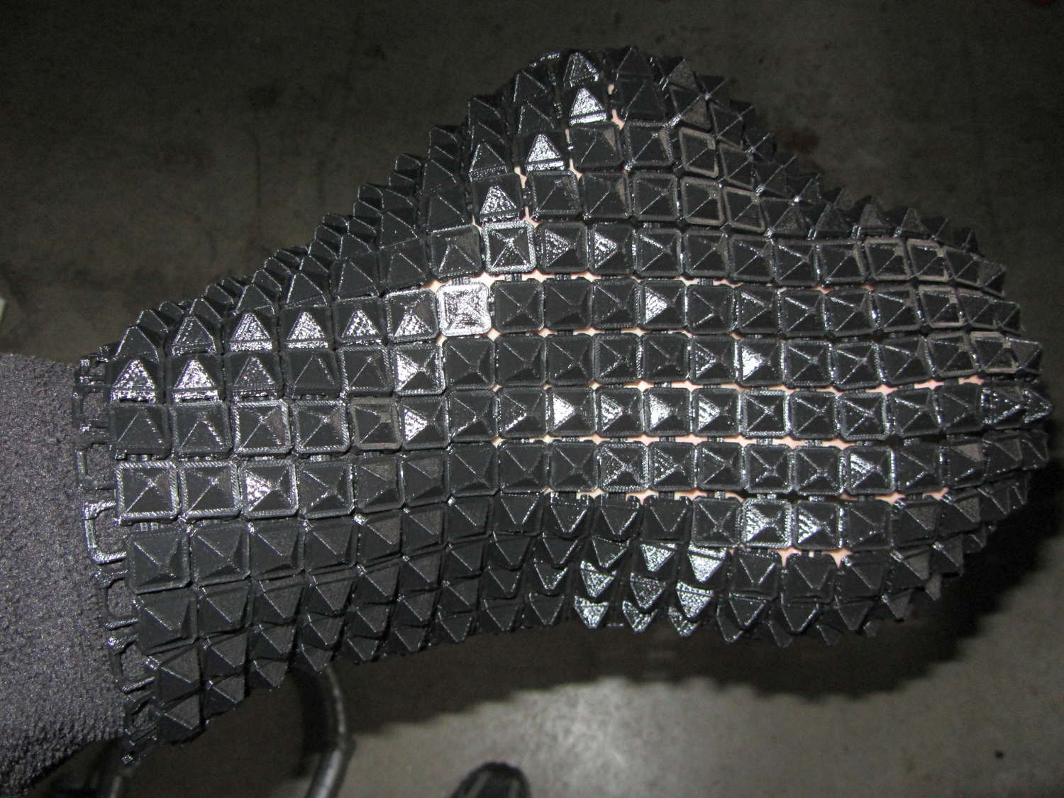
It’s not actually fabric, but it’s sufficiently bendy to cover a hand:
Chain Mail Armor – joined sheet draped on hand
The thing just cries out to be fondled…
There’s a quarter kilogram of plastic in that 8×12 inch = 200×310 mm sheet that almost used up the last of the black PLA spool.
Remember: you must tweak the OpenSCAD code to match your extruder settings, export a suitable STL file, get really compulsive about platform alignment, use hairspray / glue stick to boost platform adhesion, and have no qualms about an all-day print run. You can’t just slice a random STL file produced for a different printer, because the link dimensions come directly from the printer’s capabilities: one size does not fit all.
The OpenSCAD source code [Update: This is the refactored version.]:
// Chain Mail Armor Buttons
// Ed Nisley KE4ZNU - December 2014

Layout = "Build";			// Link Button LB Joiner Joiners Build

//-------
//- Extrusion parameters must match reality!
//  Print with 1 shell and 2+2 solid layers

ThreadThick = 0.20;
ThreadWidth = 0.40;

HoleWindage = 0.2;

Protrusion = 0.1*ThreadThick;			// make holes end cleanly

function IntegerMultiple(Size,Unit) = Unit * ceil(Size / Unit);

//-------
// Dimensions

//- Set maximum sheet size

SheetSizeX = 50;	// 170 for full sheet on M2
SheetSizeY = 60;	// 230

//- Diamond or rectangular sheet?

Diamond = false;					// true = rotate 45 degrees, false = 0 degrees for square

BendAround = "X";					// X or Y = maximum flexibility *around* designated axis

Cap = true;										// true = build bridge layers over links

Armor = true && Cap;							// true = build armor button atop (required) cap
ArmorThick = IntegerMultiple(6,ThreadThick);	// height above cap surface

// Link bar sizes

BarWidth = 6 * ThreadWidth;
BarThick = 4 * ThreadThick;

BarClearance = 5*ThreadThick;		// vertical clearance above & below bars

//-- Compute link sizes from those values

// Absolute minimum base link: bar width + corner angle + build clearance around bars
//  rounded up to multiple of thread width to ensure clean filling
BaseSide = IntegerMultiple((4*BarWidth + 2*BarWidth/sqrt(2) + 3*(2*ThreadWidth)),ThreadWidth);

BaseHeight = 2*BarThick + BarClearance;           // both bars + clearance

echo(str("BaseSide: ",BaseSide," BaseHeight: ",BaseHeight));
echo(str(" Base elements: ",4*BarWidth,", ",2*BarWidth/sqrt(2),", ",3*(2*ThreadWidth)));
echo(str(" total: ",(4*BarWidth + 2*BarWidth/sqrt(2) + 3*(2*ThreadWidth))));

BaseOutDiagonal = BaseSide*sqrt(2) - BarWidth;
BaseInDiagonal = BaseSide*sqrt(2) - 2*(BarWidth/2 + BarWidth*sqrt(2));

echo(str("Outside diagonal: ",BaseOutDiagonal));

//- On-center distance measured along coordinate axis
//   the links are interlaced, so this is half of what you think it should be...

LinkOC = BaseSide/2 + ThreadWidth;

LinkSpacing = Diamond ? (sqrt(2)*LinkOC) : LinkOC;
echo(str("Base spacing: ",LinkSpacing));

//- Compute how many links fit in sheet

MinLinksX = ceil((SheetSizeX - (Diamond ? BaseOutDiagonal : BaseSide)) / LinkSpacing);
MinLinksY = ceil((SheetSizeY - (Diamond ? BaseOutDiagonal : BaseSide)) / LinkSpacing);
echo(str("MinLinks X: ",MinLinksX," Y: ",MinLinksY));

NumLinksX = ((0 == (MinLinksX % 2)) && !Diamond) ? MinLinksX + 1 : MinLinksX;
NumLinksY = ((0 == (MinLinksY % 2) && !Diamond)) ? MinLinksY + 1 : MinLinksY;
echo(str("Links X: ",NumLinksX," Y: ",NumLinksY));

//- Armor button base

CapThick = 4 * ThreadThick;						// at least 3 layers for solid bridging

ButtonHeight = BaseHeight + BarClearance + CapThick;
echo(str("ButtonHeight: ",ButtonHeight));

//- Armor ornament size & shape
//		Fine-tune OD & ID to suit the number of sides...

ArmorSides = 4;
ArmorAngle = true ? 180/ArmorSides : 0;			// true -> rotate half a side for best alignment

TotalHeight = ButtonHeight + ArmorThick;
echo(str("Overall Armor Height: ",TotalHeight));

ArmorOD = 1.1 * BaseSide;						// tune for best base fit
ArmorID = 10 * ThreadWidth;						// make the tip blunt & strong

//-------

module ShowPegGrid(Space = 10.0,Size = 1.0) {

  RangeX = floor(95 / Space);
  RangeY = floor(125 / Space);

	for (x=[-RangeX:RangeX])
	  for (y=[-RangeY:RangeY])
		translate([x*Space,y*Space,Size/2])
		  %cube(Size,center=true);

}

//-------
// Create link with armor button as needed

module Link(Topping = false) {

LinkHeight = (Topping && Cap) ? ButtonHeight : BaseHeight;

render(convexity=3)
	rotate((BendAround == "X") ? 90 : 0)
	rotate(Diamond ? 45 : 0)
		union() {
			difference() {
				translate([0,0,LinkHeight/2])	// outside shape
					intersection() {
						cube([BaseSide,BaseSide,LinkHeight],center=true);
						rotate(45)
							cube([BaseOutDiagonal,BaseOutDiagonal,LinkHeight],center=true);
					}
				translate([0,0,(BaseHeight + BarClearance - Protrusion)/2])
					intersection() {		// inside shape
						cube([(BaseSide - 2*BarWidth),
								(BaseSide - 2*BarWidth),
								(BaseHeight + BarClearance + Protrusion)],
								center=true);
						rotate(45)
							cube([BaseInDiagonal,
									BaseInDiagonal,
									(BaseHeight + BarClearance + Protrusion)],
									center=true);
				}

				translate([0,0,((BarThick + 2*BarClearance)/2 + BarThick)])		// openings for bars
					cube([(BaseSide - 2*BarWidth - 2*BarWidth/sqrt(2)),
						(2*BaseSide),
						BarThick + 2*BarClearance],
						center=true);

				translate([0,0,(BaseHeight/2 - BarThick)])
					cube([(2*BaseSide),
						(BaseSide - 2*BarWidth - 2*BarWidth/sqrt(2)),
						BaseHeight],
						center=true);

			}

			if (Topping && Armor)
				translate([0,0,(ButtonHeight - Protrusion)])		// sink slightly into the cap
					rotate(ArmorAngle)
					cylinder(d1=ArmorOD,
							 d2=ArmorID,
							 h=(ArmorThick + Protrusion),
							 $fn=ArmorSides);
		}
}

//-------
// Create split buttons to join sheets

module Joiner() {

	translate([-LinkSpacing,0,0])
		difference() {
			Link(false);
			translate([0,0,BarThick + BarClearance + TotalHeight/2 - Protrusion])
				cube([2*LinkSpacing,2*LinkSpacing,TotalHeight],center=true);
		}

	translate([LinkSpacing,0,0])
		intersection() {
			translate([0,0,-(BarThick + BarClearance)])
				Link(true);
			translate([0,0,TotalHeight/2])
				cube([2*LinkSpacing,2*LinkSpacing,TotalHeight],center=true);
		}

}

//-------
// Build it!

ShowPegGrid();

if (Layout == "Link") {
	Link(false);
}

if (Layout == "Button") {
	Link(true);
}

if (Layout == "LB") {
	Link(true);
	translate([LinkSpacing,LinkSpacing,0])
		Link(false);
}

if (Layout == "Build")
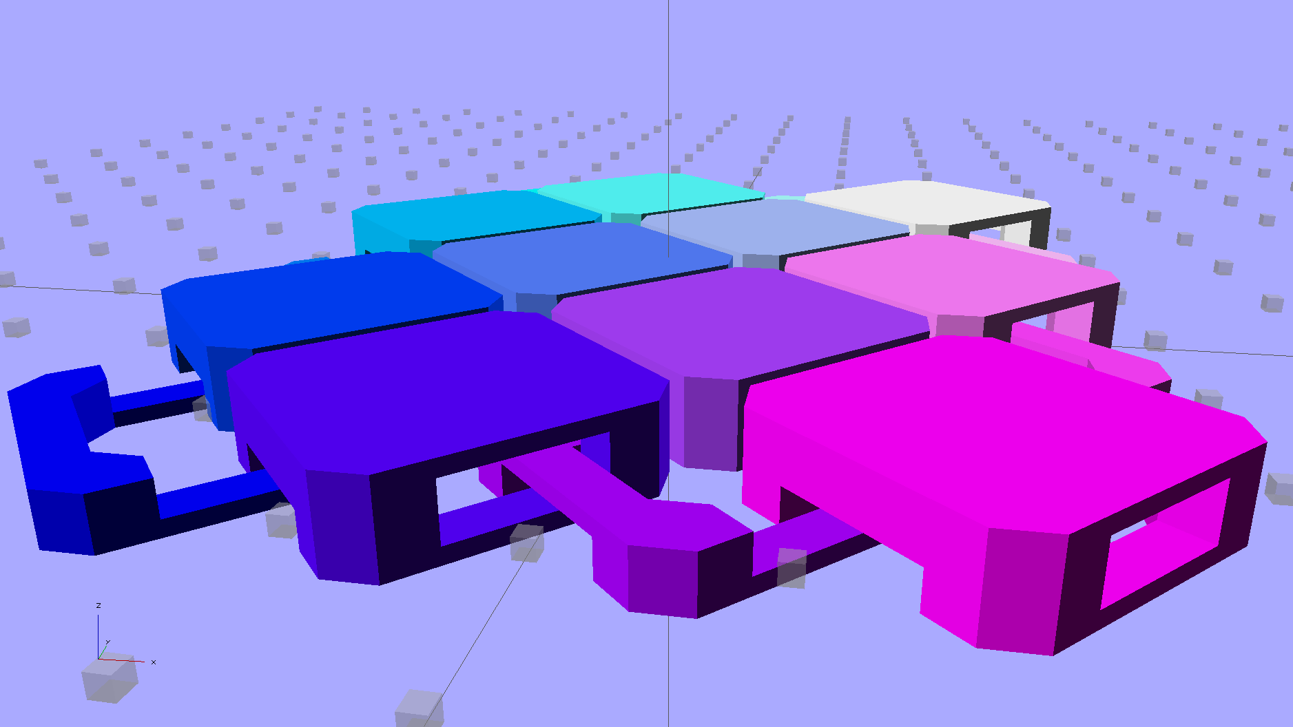
	for (ix = [0:(NumLinksX - 1)],
		 iy = [0:(NumLinksY - 1)]) {
			x = (ix - (NumLinksX - 1)/2)*LinkSpacing;
			y = (iy - (NumLinksY - 1)/2)*LinkSpacing;
			translate([x,y,0])
			color([(ix/(NumLinksX - 1)),(iy/(NumLinksY - 1)),1.0])
				if (Diamond)
					Link((ix + iy) % 2);					// armor at odd,odd & even,even points
				else
					if ((iy % 2) && (ix % 2))				// armor at odd,odd points
                        Link(true);
					else if (!(iy % 2) && !(ix % 2))		// connectors at even,even points
						Link(false);
	}

if (Layout == "Joiner")
	Joiner();

if (Layout == "Joiners") {
	NumJoiners = max(MinLinksX,MinLinksY)/2;
	for (iy = [0:(NumJoiners - 1)]) {
		y = (iy - (NumJoiners - 1)/2)*2*LinkSpacing + LinkSpacing/2;
		translate([0,y,0])
			color([0.5,(iy/(NumJoiners - 1)),1.0])
				Joiner();
	}
}
As a reward for reading all the way to the bottom, some further thoughts:
A mask array could control what type of link goes where, which cap style goes on each armor button, and whether to print the link at all. That way, you could produce customized armor buttons in non-rectangular (albeit coarsely pixelized) fabric sheets.
You could produce an armor sheet sporting cubic caps, then intersect the whole sheet with a model built from a height-map image to spread a picture across the sheet. The complexity of that model would probably tie OpenSCAD in knots, but perhaps an external program could intersect two properly aligned STL / AMF files.
The bars could be a thread or two thinner, shaving a few millimeters off the basic link. The printer’s ability to bridge the link to form the flying bars and cap limits making the links much larger.
Starting from the improved chain mail link design, extend the top bars enough to clear the cross links, then bridge across them to form a flat cap:
Chain Mail – Armor and Link
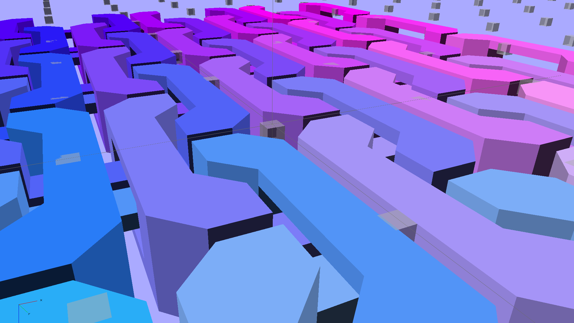
The OpenSCAD code makes the links as small as they can possibly be, based on the bar size and clearances, then rounds up to a multiple of the thread width so the flat cap will fill properly. Given the extrusion thread dimensions and the bar sizes, the OpenSCAD code computes everything else: the link model matches the slicer settings that define the printer’s output.
Given:
Thread: 0.4 mm wide x 0.2 mm thick
Bar: 6 thread wide x 4 thread thick = 2.4 x 0.8 mm
Clearances: 2 thread horizontal x 5 thread vertical = 0.8 x 1.0 mm
All the links measure 15.6 mm from side to side, the short connecting links are 2.6 mm tall, and the flat caps are 4.4 mm tall. Interlinked links sit 8.2 mm on center = half the link side plus one thread width clearance, which is 16.4 mm on center for adjacent links.
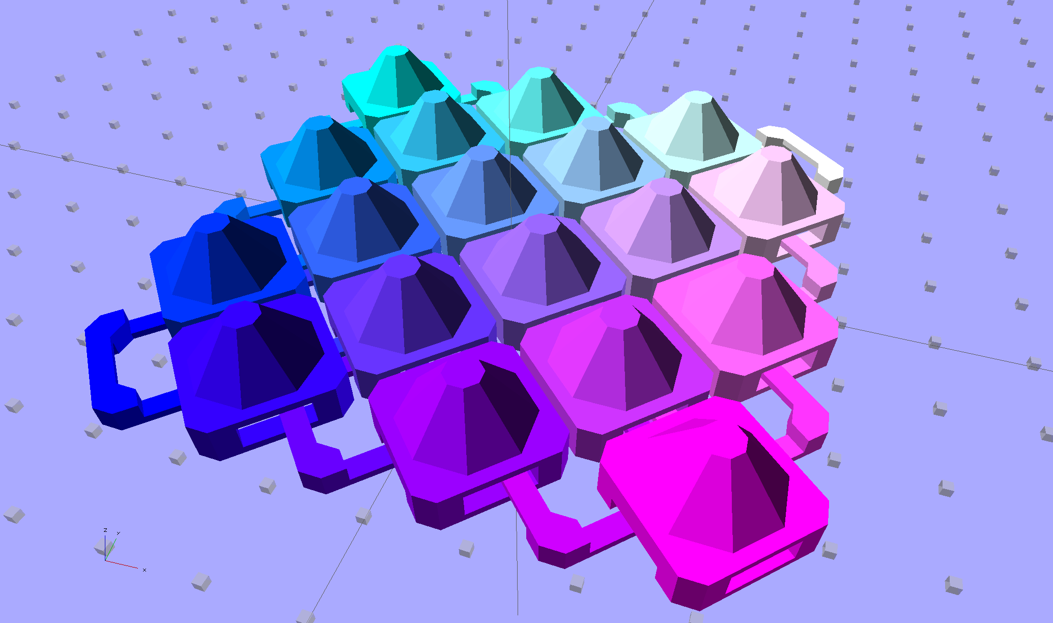
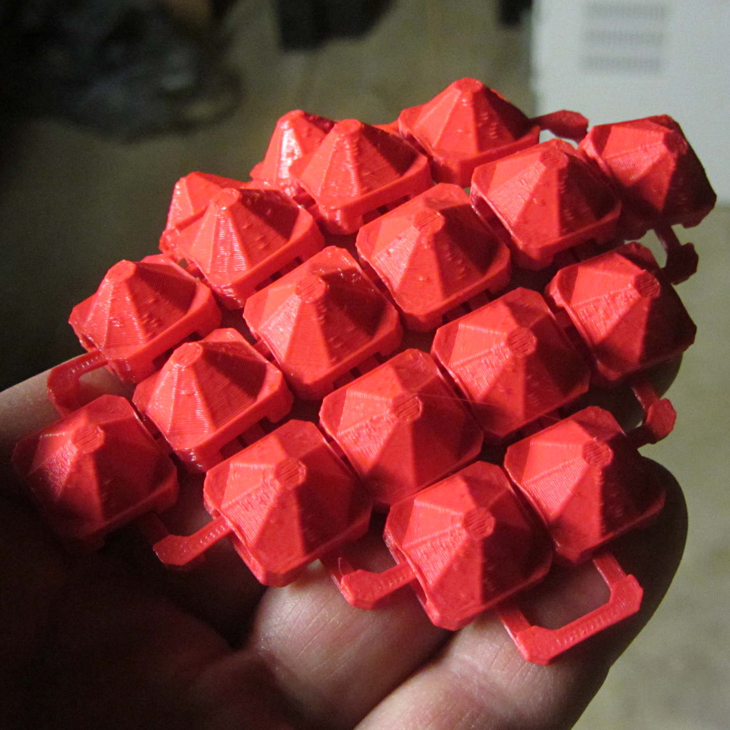
Duplicated appropriately, the caps resemble turtle armor:
Chain Mail – Flat Armor
Which look about the same in real life, minus the cheerful colors:
Armor Buttons – on platform – side
Now, however, you can plunk an armor button atop the cap:
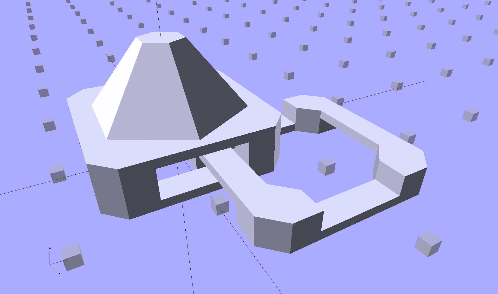
Chain Mail Armor – 4 sided
With any number of sides:
Chain Mail Armor – 6 sided
Up to a truncated cone:
Chain Mail Armor – 24 sided
The flat tip makes the button more durable and user-friendly, but you can make it a bit more pointy if you favor that sort of thing. The button adds 6 mm to the link base, making armor links 10.4 mm tall.
Other printable stuff could fit on that cap: letters, decorations, widgets, whatever.
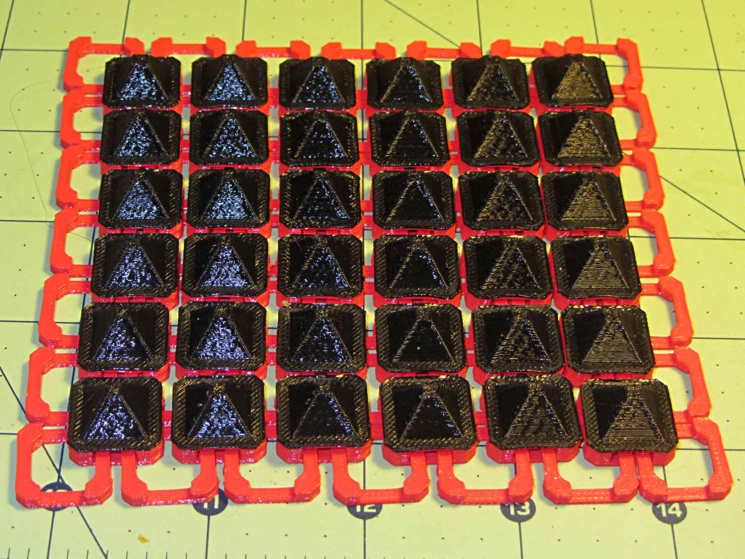
I think square armor buttons look ever so imposing when they’re arrayed in a sheet:
Chain Mail Armor – square – 4 sided
The general idea being that you could attach the armor sheet to a cloth / leather backing to form a gauntlet or greave; the border of bottom links around the button array should serve for that purpose.
The plastic prints just like the model and pops off the M2’s platform ready to use, with no finishing required:
Chain Mail Armor – square on desk
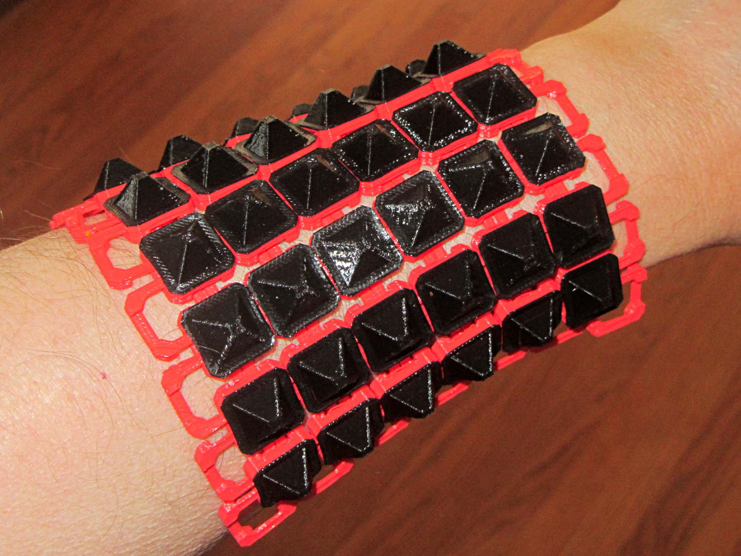
The two-color effect came from hot-swapping black filament as the red PLA ran out. The 6×6 armor button array and the 7×7 connecting link array holding it together required 14 meters of filament and I guesstimated the red spool held 9 meters: I was ready when the last of the red vanished just after completing the bridging layer under the flat caps. Filament swaps work reasonably well; I’d hate to do that on a production basis.
If you don’t mind my saying so, everybody thinks it’s spectacular:
Chain Mail Armor – square on arm
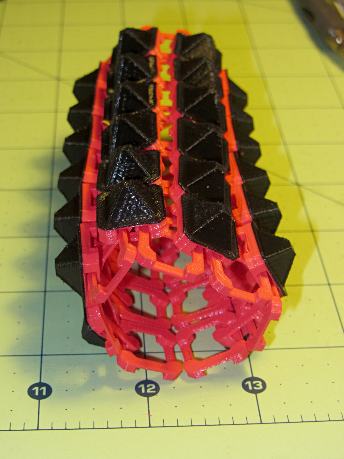
The sheet has a definite “grain” defined by the orientation of the bottom links, making it far more bendy in one direction than the other:
Chain Mail Armor – square rolled
The sheet layout orients the more-bendy direction along the M2’s (longer) Y axis, so that sheets can wrap snugly around your arm (or leg) and extend straight-ish along the bones in the other direction. That should be configurable, I think.
There’s an option to rotate the links by 45° to produce diamond-theme arrays:
Chain Mail Armor – diamond – 8 sided
Which would make good patch armor, if you’re into that sort of thing:
Chain Mail Armor – diamond on hand
Those have octagonal buttons, which IMHO don’t look nearly as crisp as the four-sided version.
Ah! I should generalize the diamond rotation option to select all four useful rotations.
The 6×6 square sheet requires three hours on the M2, with the intial print time estimates being low by nearly a factor of two. The M2 has a 200×250 mm platform and I’ll definitely try a full-size array just to see how it works.
The OpenSCAD source code, which stands badly in need of refactoring:
// Chain Mail Armor Buttons
// Ed Nisley KE4ZNU - November 2014

Layout = "Build";			// Link Button LB Build

//-------
//- Extrusion parameters must match reality!
//  Print with 1 shell and 2+2 solid layers

ThreadThick = 0.20;
ThreadWidth = 0.40;

HoleWindage = 0.2;

Protrusion = 0.1;			// make holes end cleanly

function IntegerMultiple(Size,Unit) = Unit * ceil(Size / Unit);

//-------
// Dimensions

//- Set maximum sheet size

SheetSizeX = 70;
SheetSizeY = 80;

//- Diamond or rectangular sheet?

Diamond = false;					// true = rotate 45 degrees, false = 0 degrees for square
ArmorButton = true;					// true = build button atop cap

// Link bar sizes

BarWidth = 6 * ThreadWidth;
BarThick = 4 * ThreadThick;

BarClearance = 5*ThreadThick;		// vertical clearance above & below bars

//-- Compute link sizes from those values

// Absolute minimum base link: bar width + corner angle + build clearance around bars
//  rounded up to multiple of thread width to ensure clean filling
BaseSide = IntegerMultiple((4*BarWidth + 2*BarWidth/sqrt(2) + 3*(2*ThreadWidth)),ThreadWidth);

BaseHeight = 2*BarThick + BarClearance;           // both bars + clearance

echo(str("BaseSide: ",BaseSide," BaseHeight: ",BaseHeight));

BaseOutDiagonal = BaseSide*sqrt(2) - BarWidth;
BaseInDiagonal = BaseSide*sqrt(2) - 2*(BarWidth/2 + BarWidth*sqrt(2));

echo(str("Outside diagonal: ",BaseOutDiagonal));

//- On-center distance measured along coordinate axis

LinkOC = BaseSide/2 + ThreadWidth;

LinkSpacing = Diamond ? (sqrt(2)*LinkOC) : LinkOC;
echo(str("Base spacing: ",LinkSpacing));

//- Compute how many links fit in sheet

MinLinksX = ceil((SheetSizeX - (Diamond ? BaseOutDiagonal : BaseSide)) / LinkSpacing);
MinLinksY = ceil((SheetSizeY - (Diamond ? BaseOutDiagonal : BaseSide)) / LinkSpacing);
echo(str("MinLinks X: ",MinLinksX," Y: ",MinLinksY));

NumLinksX = ((0 == (MinLinksX % 2)) && !Diamond) ? MinLinksX + 1 : MinLinksX;
NumLinksY = ((0 == (MinLinksY % 2) && !Diamond)) ? MinLinksY + 1 : MinLinksY;
echo(str("Links X: ",NumLinksX," Y: ",NumLinksY," Total: ",NumLinksX*NumLinksY));

//- Armor button base

CapThick = BarThick;

ButtonHeight = BaseHeight + BarClearance + CapThick;
echo(str("ButtonHeight: ",ButtonHeight));

//- Armor ornament size & shape

ArmorSides = 4;
ArmorAngle = true ? 180/ArmorSides : 0;			// rotate half a side?

ArmorThick = IntegerMultiple(6,ThreadThick);	// keep it relatively short

ArmorOD = 1.1 * BaseSide;						// tune for best fit at base

ArmorID = 10 * ThreadWidth;						// make the tip wide & strong

//-------

module ShowPegGrid(Space = 10.0,Size = 1.0) {

  RangeX = floor(95 / Space);
  RangeY = floor(125 / Space);

	for (x=[-RangeX:RangeX])
	  for (y=[-RangeY:RangeY])
		translate([x*Space,y*Space,Size/2])
		  %cube(Size,center=true);

}

//-------
// Create base link

module BaseLink() {

render()
	rotate(Diamond ? 45 : 90)			// 90 = more bendy around X axis
		difference() {
			translate([0,0,BaseHeight/2]) {
				difference(convexity=2) {
					intersection() {		// outside shape
						cube([BaseSide,BaseSide,BaseHeight],center=true);
						rotate(45)
							cube([BaseOutDiagonal,BaseOutDiagonal,BaseHeight],center=true);
					}
					intersection() {		// inside shape
						cube([(BaseSide - 2*BarWidth),
							  (BaseSide - 2*BarWidth),
							  (BaseHeight + 2*Protrusion)],
							 center=true);
						rotate(45)
							cube([BaseInDiagonal,
								  BaseInDiagonal,
								  (BaseHeight +2*Protrusion)],
								 center=true);
					}
				}
			}

			translate([0,0,(BaseHeight/2 + BarThick)])
				cube([(BaseSide - 2*BarWidth - 2*BarWidth/sqrt(2)),
					  (2*BaseSide),
					  BaseHeight],
					 center=true);
			translate([0,0,(BaseHeight - BaseHeight/2 - BarThick)])
				cube([(2*BaseSide),
					  (BaseSide - 2*BarWidth - 2*BarWidth/sqrt(2)),
					  BaseHeight],
					 center=true);
		}
}

//-------
// Create button link

module ButtonLink() {

render()
	rotate(Diamond ? 45 : 90)			// 90 = more bendy around X axis
		union() {
			difference() {
				translate([0,0,ButtonHeight/2])		// outside shape
					intersection() {
						cube([BaseSide,BaseSide,ButtonHeight],center=true);
						rotate(45)
							cube([BaseOutDiagonal,BaseOutDiagonal,ButtonHeight],center=true);
					}
				translate([0,0,(BaseHeight + BarClearance - Protrusion)/2])
					intersection() {		// inside shape
						cube([(BaseSide - 2*BarWidth),
								(BaseSide - 2*BarWidth),
								(BaseHeight + BarClearance + Protrusion)],
								center=true);
						rotate(45)
							cube([BaseInDiagonal,
									BaseInDiagonal,
									(BaseHeight + BarClearance + Protrusion)],
									center=true);
				}

				translate([0,0,((BarThick + 2*BarClearance)/2 + BarThick)])
					cube([(BaseSide - 2*BarWidth - 2*BarWidth/sqrt(2)),
						(2*BaseSide),
						BarThick + 2*BarClearance],
						center=true);

				translate([0,0,(BaseHeight/2 - BarThick)])
					cube([(2*BaseSide),
						(BaseSide - 2*BarWidth - 2*BarWidth/sqrt(2)),
						BaseHeight],
						center=true);

			}

			if (ArmorButton)
				translate([0,0,(ButtonHeight - Protrusion)])		// armor on cap
					rotate(ArmorAngle)
					cylinder(d1=ArmorOD,
							 d2=ArmorID,
							 h=(ArmorThick + Protrusion),
							 $fn=ArmorSides);
		}
}

//-------
// Build it!

ShowPegGrid();

if (Layout == "Link") {
	BaseLink();
}

if (Layout == "Button") {
	ButtonLink();
}

if (Layout == "LB") {
	ButtonLink();
	translate([LinkSpacing,LinkSpacing,0])
		BaseLink();
}

if (Layout == "Build") {
	for (ix = [0:(NumLinksX - 1)],
		 iy = [0:(NumLinksY - 1)])
			assign(x = (ix - (NumLinksX - 1)/2)*LinkSpacing,
				   y = (iy - (NumLinksY - 1)/2)*LinkSpacing)
			translate([x,y,0])
			color([(ix/(NumLinksX - 1)),(iy/(NumLinksY - 1)),1.0])
				if (Diamond)
					if ((ix + iy) % 2)						// armor at odd,odd & even, even points
						ButtonLink();
					else
						BaseLink();							// connectors otherwise
				else
					if ((iy % 2) && (ix % 2))				// armor at odd,odd points
						ButtonLink();
					else if ((!(iy % 2) && !(ix % 2)))		// connectors at even,even points
						BaseLink();
}
The rectangular posts in my chain mail resemble Zomboe’s original design, but with dimensions computed directly from the bar (and, thus, thread) widths and thicknesses to ensure good fill and simple bridging:
Chain Mail Link
They fit together well, but the angled post edges make the bridge threads longer than absolutely necessary along the outside edge of each link:
Chain Mail Sheet – detail
A bit of fiddling produces a squared-off version:
Chain Mail Link – Improved Posts
Which nest together like this:
Chain Mail – Improved Posts – Bottom View
Now all the bridge threads have the same length, which should produce better results.
Commercial LED strip lights for sewing machines mount their cables with little stick-on anchors and cable ties. I wasn’t happy with the cable tie thing and finally figured this out:
Kenmore 158 – LED strip light cable clips
The clips have that size & shape because they fit exactly atop some pre-cut foam squares from the Tape Lookaside Buffer:
LED strip light cable clips
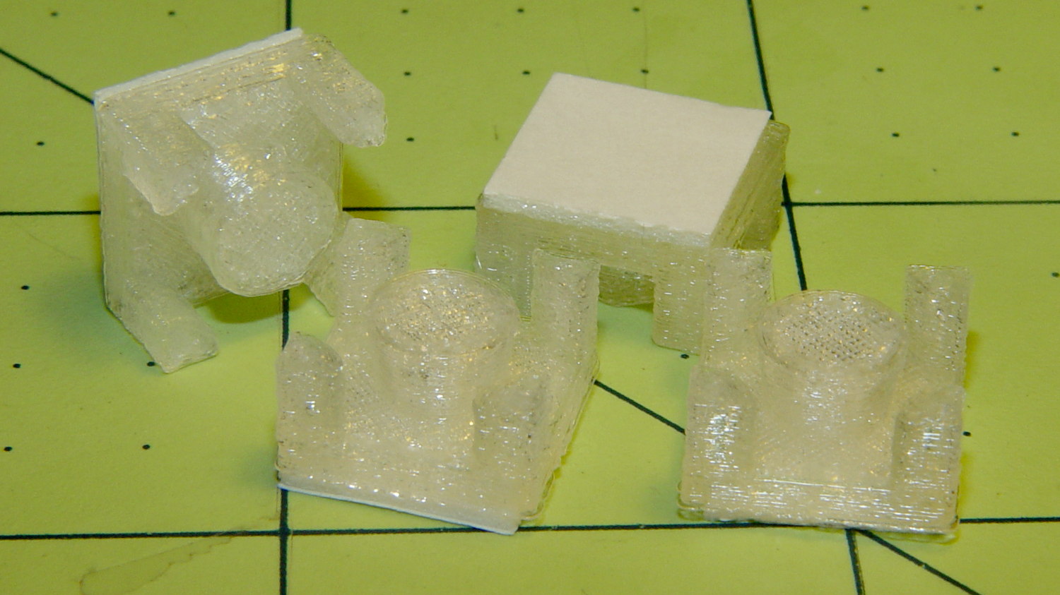
You can see the shape better in the solid model:
LED Cable Clips
The central bollard has a slight taper to retain the cable, the quarter-posts are straight, and they’re both twice the cable diameter tall. The clearance between the center and corner posts at the top matches the cable diameter, so there’s a bit of bending room at the bottom, and, with the cable bent around the center, it won’t fall out on its own.
The cute coaxial cable I’m misusing for the LED strips measures just shy of 2 mm, making these into little bitty things. The corner posts seem surprisingly strong, despite 3D printing’s reputation for crappy quality; I haven’t been able to break one off with more effort than seemed warranted.
The OpenSCAD source code:
// LED Cable Clips
// Ed Nisley - KE4ZNU - October 2014

//- Extrusion parameters must match reality!

ThreadThick = 0.20;
ThreadWidth = 0.40;

HoleWindage = 0.2;			// extra clearance

Protrusion = 0.1;			// make holes end cleanly

AlignPinOD = 1.70;			// assembly alignment pins: filament dia

function IntegerMultiple(Size,Unit) = Unit * ceil(Size / Unit);

//----------------------
// Dimensions

Base = [12.0,12.0,IntegerMultiple(2.0,ThreadThick)];	// base over sticky square

CableOD = 2.0;

BendRadius = 3.0;

Bollard = [BendRadius,(sqrt(2)*Base[0]/2 - CableOD - BendRadius),2*CableOD];
B_BOT = 0;
B_TOP = 1;
B_LEN = 2;

NumSides = 5*4;

//----------------------
// Useful routines

module PolyCyl(Dia,Height,ForceSides=0) {			// based on nophead's polyholes

  Sides = (ForceSides != 0) ? ForceSides : (ceil(Dia) + 2);

  FixDia = Dia / cos(180/Sides);

  cylinder(r=(FixDia + HoleWindage)/2,
           h=Height,
           $fn=Sides);
}

module ShowPegGrid(Space = 10.0,Size = 1.0) {

  RangeX = floor(100 / Space);
  RangeY = floor(125 / Space);

	for (x=[-RangeX:RangeX])
	  for (y=[-RangeY:RangeY])
		translate([x*Space,y*Space,Size/2])
		  %cube(Size,center=true);

}

//----------------------
// Build it

ShowPegGrid();

intersection() {
	translate([0,0,(Base[2] + Bollard[2])/2])			// overall XYZ outline
		cube(Base + [0,0,Bollard[2]],center=true);

	union() {
		translate([0,0,Base[2]/2])						// oversize mount base
			scale([2,2,1])
				cube(Base,center=true);

		for (i=[-1,1] , j=[-1,1]) {						// corner bollards
			translate([i*Base[0]/2,j*Base[1]/2,(Base[2] - Protrusion)])
				rotate(180/NumSides)
				cylinder(r=Bollard[B_BOT],h=(Bollard[B_LEN] + Protrusion),center=false,$fn=NumSides);

		translate([0,0,(Base[2] - Protrusion)])			// center tapered bollard
			cylinder(r1=Bollard[B_BOT],r2=Bollard[B_TOP],h=(Bollard[B_LEN] + Protrusion),center=false,$fn=NumSides);
		}
	}
}
Now that I think of it, maybe a round clip would look nicer. The central bollard would stay, but the circular outside rim could have three cutouts. When these fall off, I’ll give that a try.
They may be square and clunky, but they look much better than Gorilla Tape…
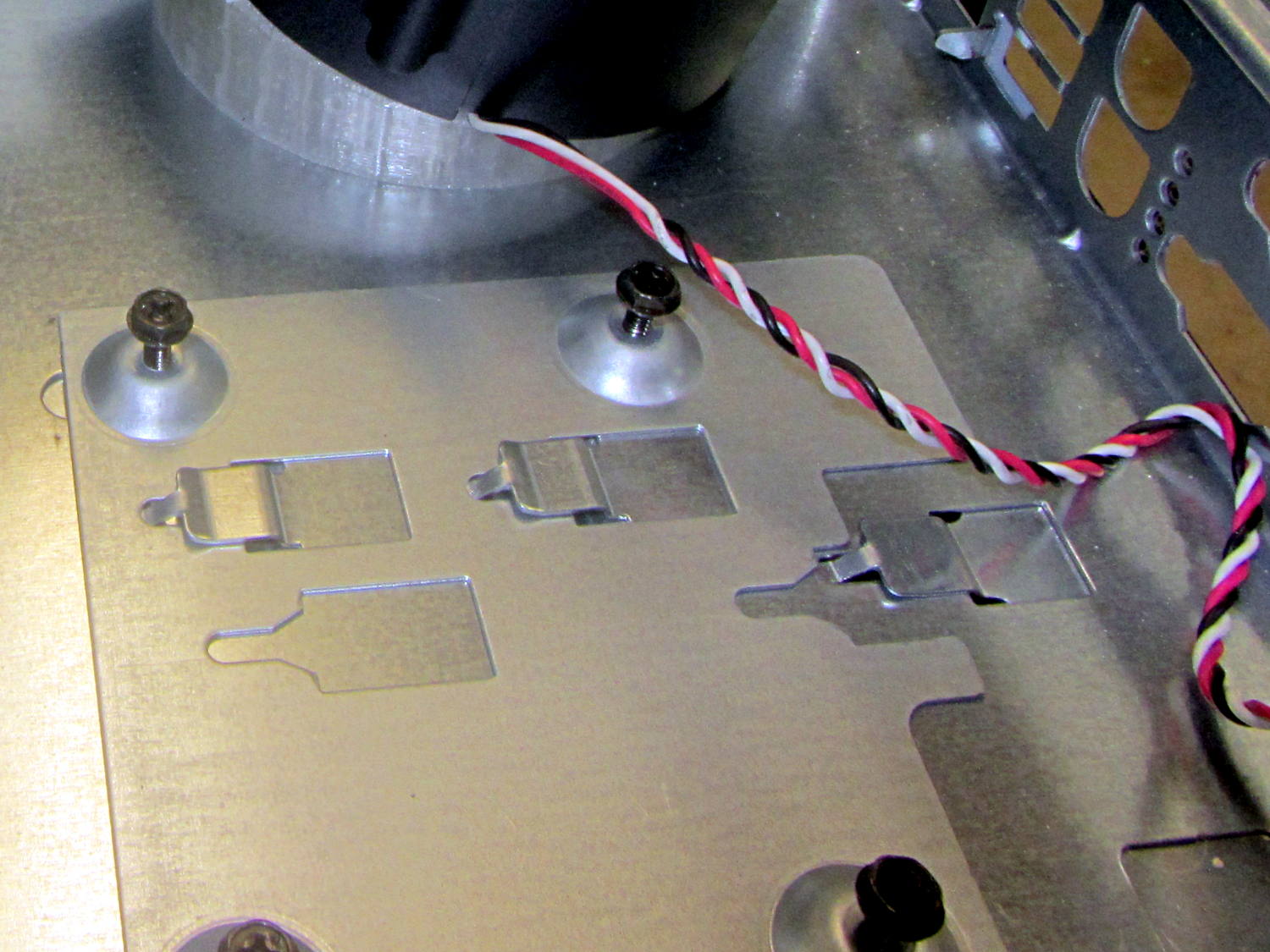
The Dell GX270 chassis has a small support plate under the CPU, evidently to support the heatsink and fan:
Optiplex GX270 CPU heatsink mount
It slides neatly into those clips on the system board tray, but it’s not actually locked into position. I think that allows it to slide around a bit under the system board, providing vertical support without constraining the board’s horizontal position. Anyhow, it looked like the easiest way to support the prototyping board that will hold the low voltage interface circuitry.
By some mischance, I found a nice aluminum plate exactly the right width, so only one side needed a saw cut and squaring. Coordinate drilling four #6 clearance holes matched the support:
LV Interface Adapter Plate – drilling
That corner of the tray had another system board retaining clip, but rather than bashing it flat, I just sawed a slit in the plate so it can slide right into position. Note the perfect alignment of that screw hole:
LV Interface Adapter Plate – retainer
I love it when all my mistakes cancel out!
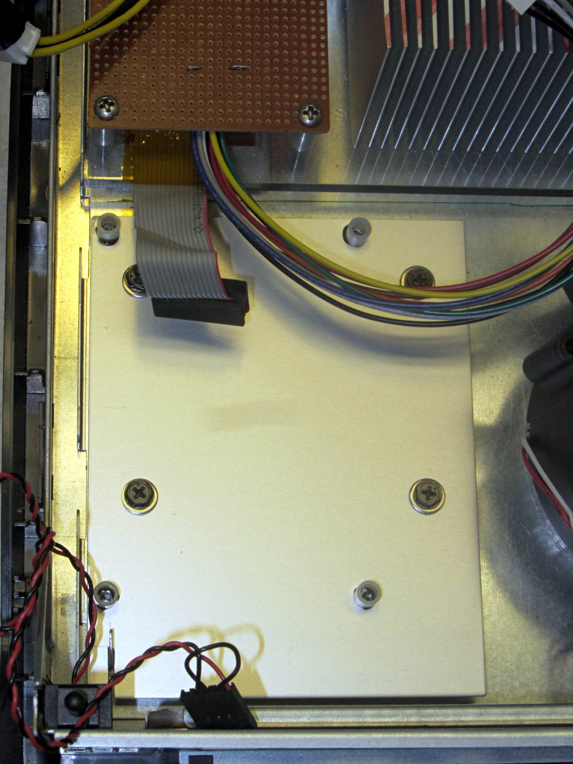
Four more holes matched the prototyping circuit board and, while I had some epoxy mixed up for another part, I fastened four standoffs over the holes. A washer under each original screw soaked up exactly enough space that the screws barely indented the case and, as if by magic, hold the support plate firmly in place:
LV Interface Adapter Plate – installed
Of course, that means I must remove the circuit board to get the tray out, but the AC interface board must also come out, so we’re not talking a spur-of-the-moment operation.
The switch in the lower left corner is the original Dell “intrusion monitoring” switch harvested from a complex metal stamping in the diagonally opposite corner of the case. It’s epoxied to the case wall, with the plunger contacting a shim epoxied to the top of the case, and will eventually disconnect the AC line power from the drive electronics: case open = switch closed = lethal power off.