Ed Nisley's Blog: Shop notes, electronics, firmware, machinery, 3D printing, laser cuttery, and curiosities. Contents: 100% human thinking, 0% AI slop.
Quite a while ago, I rebuilt a gooseneck shop lamp with an LED floodlight module, the light from which appears in many pictures of the Sherline mill. That module has a sibling that I just combined with a defunct halogen desk lamp to produce a better task light for the bench; the original 12 VAC 50 W transformer now loafs along at 4 W and ballasts the lamp base against tipping.
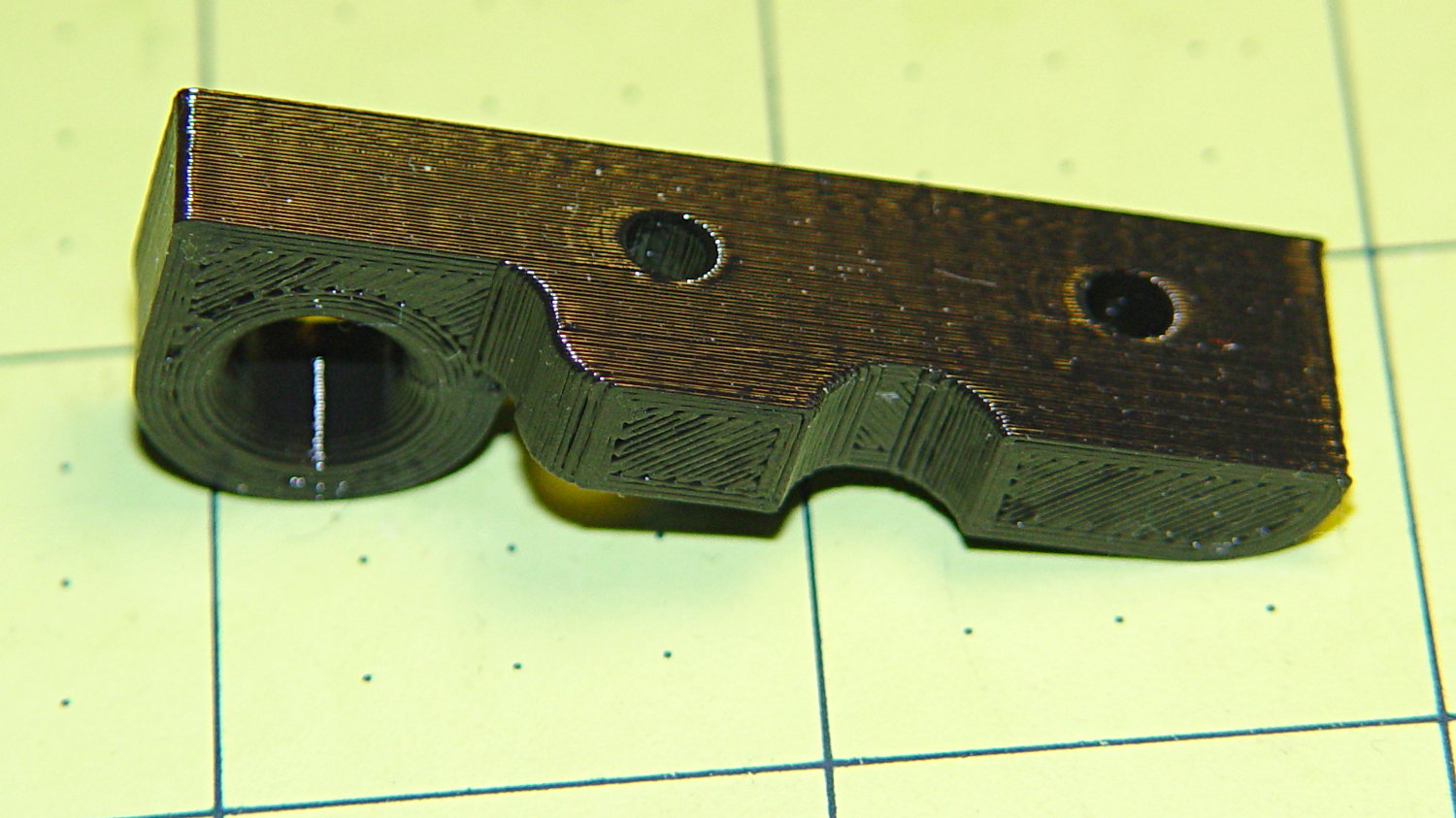
My initial idea, of course, was a 3D printed adapter from the existing arm hardware to the LED module, but PLA gets droopy at normal high-intensity LED heatsink temperatures. That led to doodling a metal bracket around the LED module flange, which led to pondering how annoying that would be to make, which led to the discovery that the screws holding the LED plug to the heatsink were ordinary M2x0.4 Philips head, which suggested I could just screw a bracket to the back of the module, which brought a recently harvested aluminum heatsink to hand, which led to the discovery that the tip of the pivot screw fit perfectly between the fins, which …
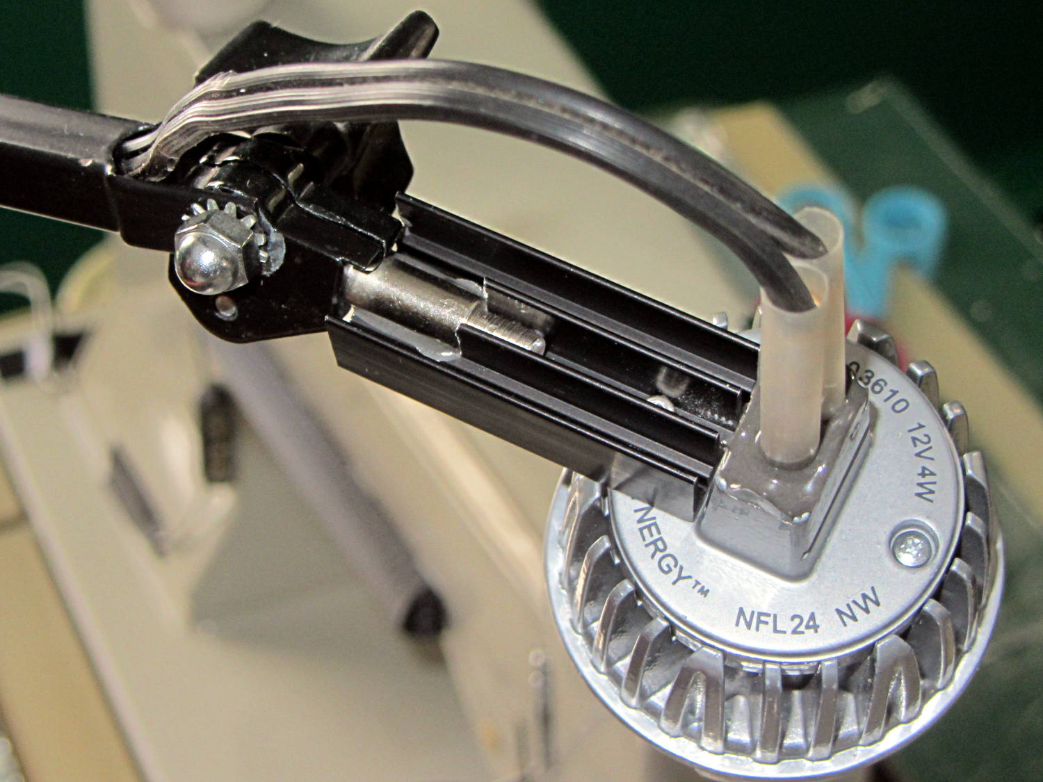
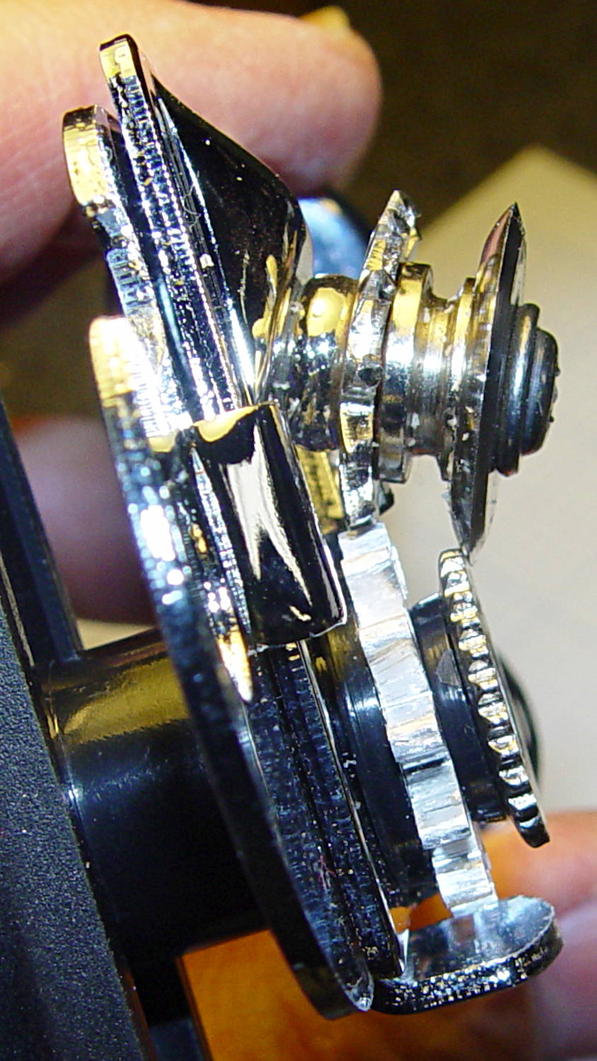
Shortly thereafter, I milled off the central fins to fit the shaft of the pivot screw, introduced the heatsink to Mr. Disk Sander to bevel the bottom, sawed the threads off the pivot, press-fit the two together, drilled a 2 mm cross-hole into the pivot, buttered it all up with epoxy, jammed a short M2 screw into the cross hole, and let the whole mess cure:
Desk Lamp LED Adapter – top view
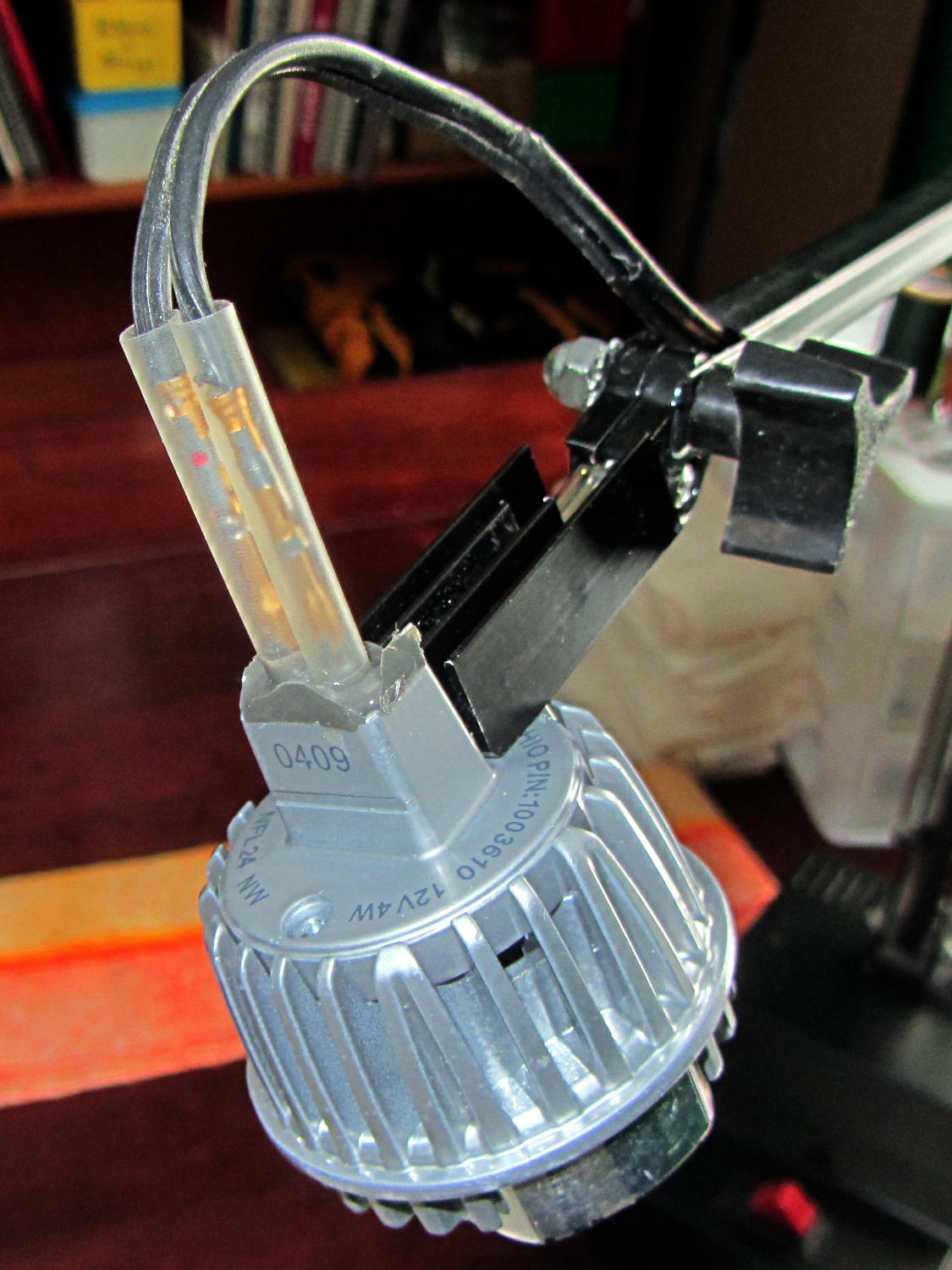
The lamp modules were a surplus find, with one pin clipped nearly flush to the insulator. I soldered a pair of the same male pins as in the battery holders, with the matching female pins as a crude connector. The unshrunk heatstink tubing isn’t lovely, but got us to First Light:
Desk Lamp LED Adapter – front view
The original counterweight is, of course, much too heavy for the dinky LED module, so I’ll drill the mounting hole for the vertical arm further back on the beam to get another foot of reach. That will require more wire between the transformer to the lamp, soooo the connectors might just become soldered joints.
As you can tell from the background, Mary snatched the lamp from my hands and put it to immediate use in The Quilting Room.
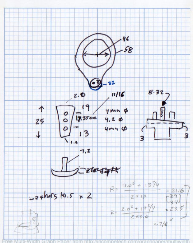
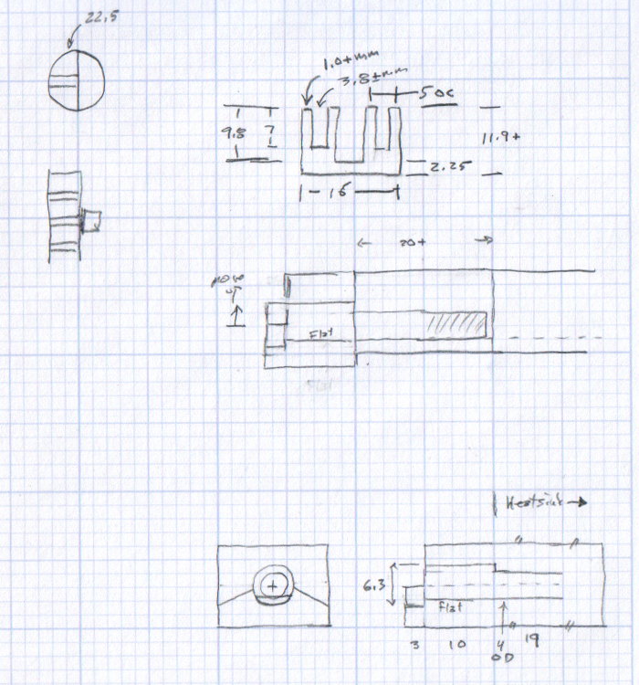
The original doodles bear no resemblance to the final product, but do have some key dimensions that (having discarded the unused hardware) I’ll likely never need again.
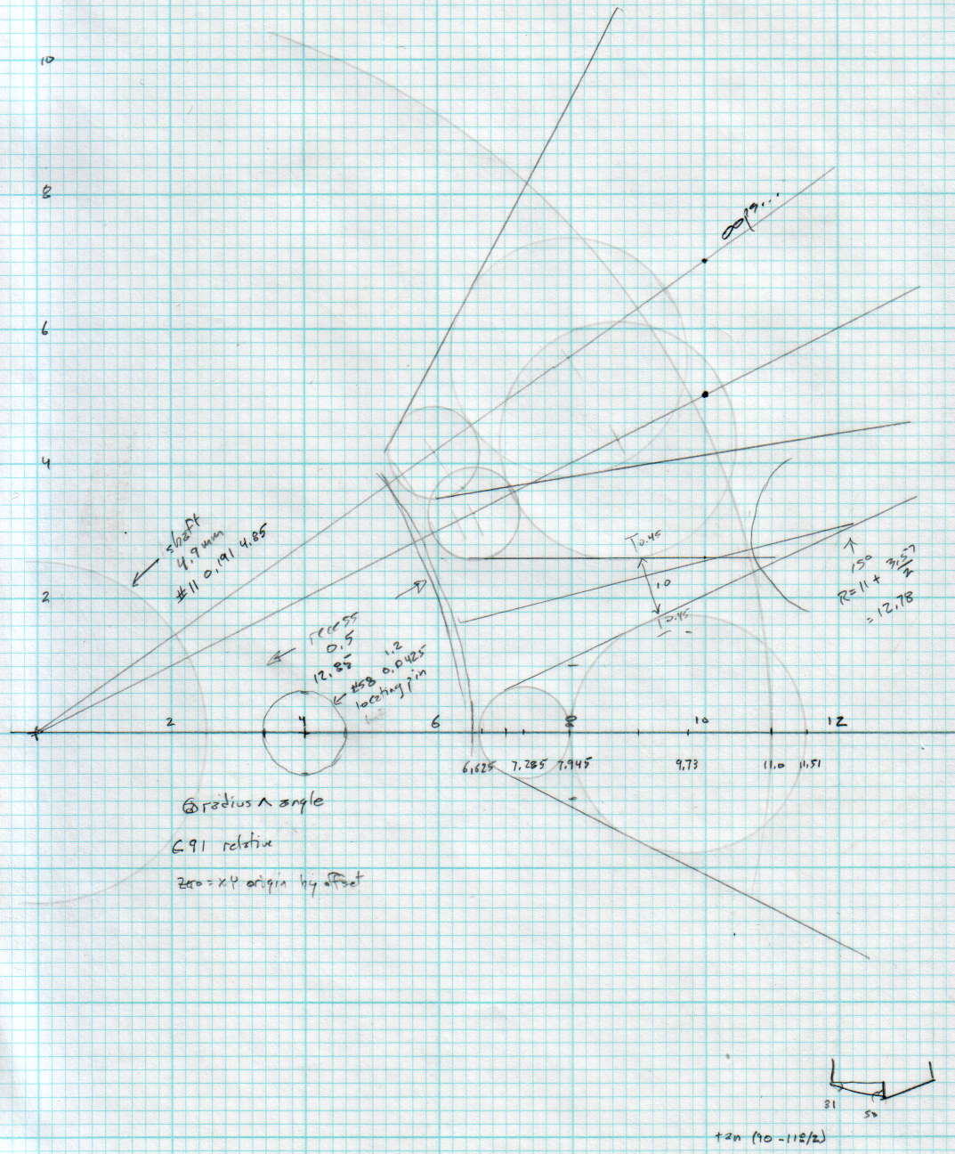
The pivot between the arm and the lamp housing, with an idea for the LED holder:
Desk Lamp Bracket Dimensions – doodle
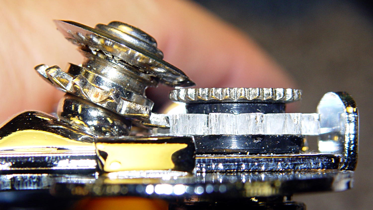
Details of the repurposed heatsink and the pivot bolt, with a block that never got built:
Although commenting out an undesired variable isn’t fashionable, OpenSCAD doesn’t have a practical mechanism to set specific values based on a control variable:
if-then-else deals with geometric objects
(boolean)?when_true:when_false (the ternary operator) doesn’t scale well
You could, of course, depend on OpenSCAD’s behavior of using the last (in syntactic order) instance of a “variable”, but IMHO that’s like depending on semantic whitespace.
In any event, the rest of the block builds itself around those three values by recomputing all of its dimensions.
The Browning OEM block looks like this:
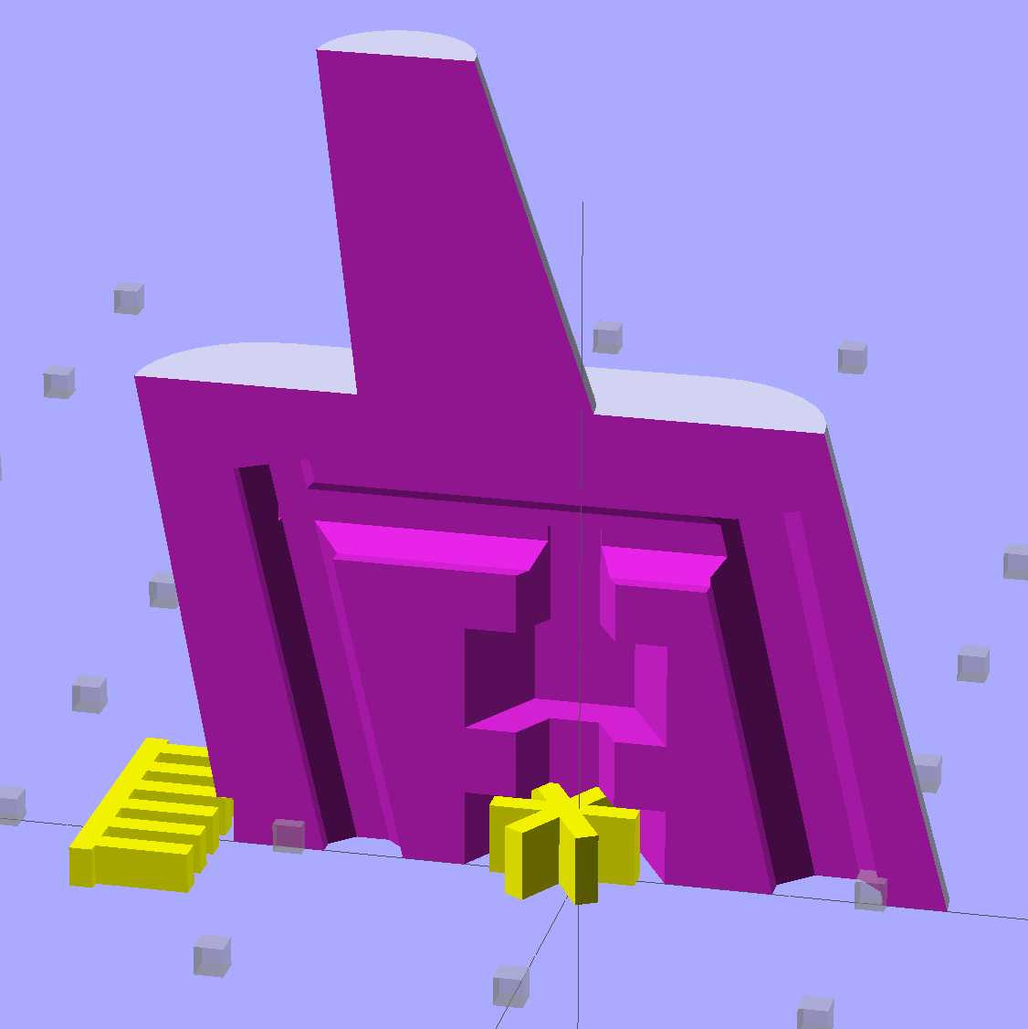
Browning Hi-Power Magazine Block – solid model – BHP OEM
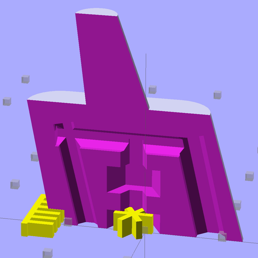
The Generic floorplate has a much larger spring retaining crimp, so the block has far more overhang:
Browning Hi-Power Magazine Block – solid model – Generic 1
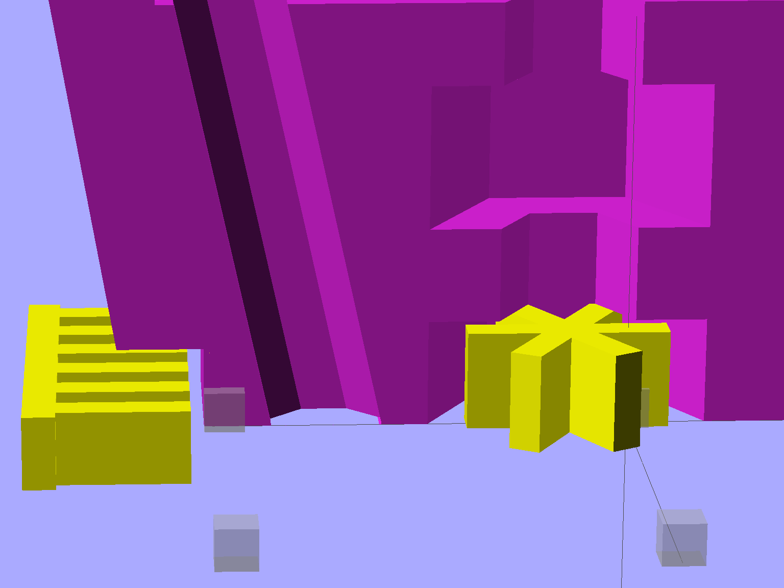
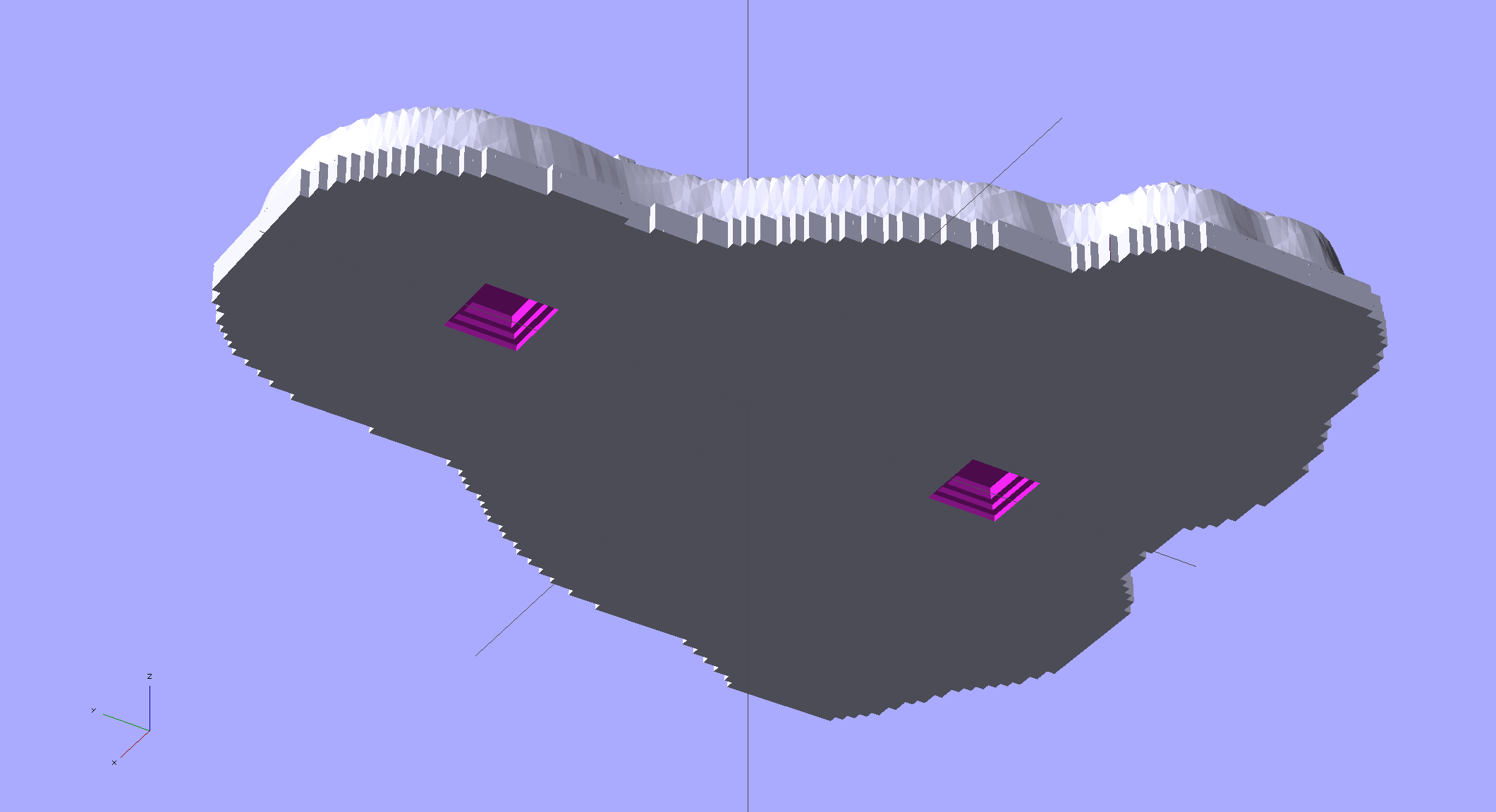
As before, the yellow widgets are built-in support structures separated from the main object by one thread thickness and width. That seems to maintain good vertical tolerance and allow easy removal; the structures snap free with minimal force. A closeup look shows the gaps:
Browning Hi-Power Magazine Block – solid model – Generic 1 – support detail
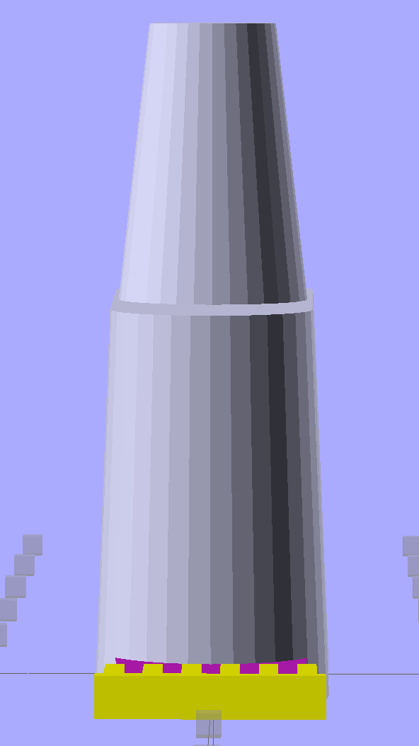
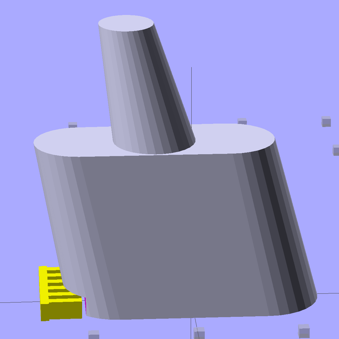
The main shape now has a 2 mm taper to ease the magazine spring past the upper edge of the block. The horn remains slightly inset from the side walls to ensure that the whole thing remains manifold:
Browning Hi-Power Magazine Block – solid model – Generic 1 – whole end
The whole object looks about the same, though:
Browning Hi-Power Magazine Block – solid model – Generic 1 – whole side
The shape descends from the geometry I used for the stainless steel block, with the additional internal channel (on the right in the models) to be filled with steel-loaded epoxy during assembly. That should make the whole block sufficiently robust that you must destroy the floorplate and distort the spring to get it out; wrecking the magazine’s innards should count as not “readily” modifiable.
Some destructive testing seems to be in order…
The OpenSCAD source code:
// Browning Hi-Power Magazine Plug
// Ed Nisley KE4ZNU December 2013
// February 2014 - easier customization for different magazine measurements
Layout = "Whole"; // Whole Show Split
// Whole = upright for steel or plastic
// Show = section view for demo, not for building
// Split = laid flat for plastic show-n-tell assembly
AlignPins = true && (Layout == "Split"); // pins only for split show-n-tell
Support = true && (Layout != "Split"); // no support for split, optional otherwise
// Define magazine measurements
//BlockData =  [-0.5, 1.5, 11.5];	// Browning OEM
BlockData = [-1.5, 2.0, 9.0];		// Generic 1

SCREWOFFSET = 0;
CRIMPHEIGHT = 1;
CRIMPDISTANCE = 2;
//- Extrusion parameters must match reality!
// Print with 2 shells and 3 solid layers
ThreadThick = 0.20;
ThreadWidth = 0.40;
HoleWindage = 0.2;
Protrusion = 0.1; // make holes end cleanly
function IntegerMultiple(Size,Unit) = Unit * ceil(Size / Unit);
//----------------------
// Dimensions
Angle = 12.5; // from vertical
SpringID = 10.3; // magazine spring curvature (measure with drill shank)
SpringRadius = SpringID / 2;
Taper = 2.0; // total taper toward top
Length = 24.5; // front-to-back perpendicular to magazine shaft
Height = 17.0; // bottom-to-top, parallel to magazine shaft
RectLength = Length - SpringID; // block length between end radii
HornBaseOD = 8.0; // fits between follower pegs to prevent shortening
HornTipOD = 5.0;
HornAddTip = (HornTipOD/2)*tan(Angle);
HornAddBase = (HornBaseOD/2)*tan(Angle);
HornAddLength = HornAddTip + HornAddBase + 2*Protrusion;
HornLength = 12.0; // should recompute ODs, but *eh*
ScrewOD = 3.0 - 0.25; // screw hole dia - minimal thread engagement
ScrewLength = Height - 5.0;
ScrewOffset = BlockData[SCREWOFFSET]; // ... from centerline on XY plane
NutOD = 5.8; // hex nut dia across flats
NutThick = 2.4; // ... generous allowance for nut
NutTrapLength = 1.5*NutThick; // allow for epoxy buildup
NutTrapBaseHeight = 5.0; // ... base height from floor plate
CrimpHeight = IntegerMultiple(BlockData[CRIMPHEIGHT],ThreadThick); // vertical clearance for spring crimp tab on base plate
CrimpDistance = BlockData[CRIMPDISTANCE]; // ... clip to screw hole center
CrimpOffset = -(CrimpDistance - ScrewOffset); // ... horizontal from centerline
SupportLength = 4.0; // length of support struts under Trim
SupportWidth = IntegerMultiple(0.9*SpringID,4*ThreadWidth); // ... size needed for platform adhesion
SupportThick = CrimpHeight - ThreadThick; // ... clearance for EZ removal
VentDia = 2.5; // air vent from back of screw recess
//VentOffset = CrimpOffset + VentDia/2 + 5*ThreadWidth;
VentOffset = -(NutOD + 4*ThreadWidth);
VentLength = ScrewLength + VentDia;
RecessDia = 3.5; // additional air vent + weight reduction
RecessLength = ScrewLength + RecessDia/2; // ... internal length
RecessOffset = Length/2 - RecessDia/2 - 5*ThreadWidth; // ... offset from centerline
PinOD = 1.72; // alignment pins
PinLength = 4.0;
PinInset = 0.6*SpringRadius; // from outside edges
echo(str("Alignment pin length: ",PinLength));
NumSides = 8*4; // default cylinder sides
Offset = 5.0/2; // from centerline for build layout
//----------------------
// Useful routines
function Delta(a,l) = l*tan(a); // incremental length due to angle
// Locating pin hole with glue recess
// Default length is two pin diameters on each side of the split
module LocatingPin(Dia=PinOD,Len=0.0) {
PinLen = (Len != 0.0) ? Len : (4*Dia);
translate([0,0,-ThreadThick])
PolyCyl((Dia + 2*ThreadWidth),2*ThreadThick,4);
translate([0,0,-2*ThreadThick])
PolyCyl((Dia + 1*ThreadWidth),4*ThreadThick,4);
translate([0,0,-(Len/2 + ThreadThick)])
PolyCyl(Dia,(Len + 2*ThreadThick),4);
}
module PolyCyl(Dia,Height,ForceSides=0) { // based on nophead's polyholes
Sides = (ForceSides != 0) ? ForceSides : (ceil(Dia) + 2);
FixDia = Dia / cos(180/Sides);
cylinder(r=(FixDia + HoleWindage)/2,
h=Height,
$fn=Sides);
}
module ShowPegGrid(Space = 10.0,Size = 1.0) {
Range = floor(50 / Space);
for (x=[-Range:Range])
for (y=[-Range:Range])
translate([x*Space,y*Space,Size/2])
%cube(Size,center=true);
}
//----------------------
// The magazine block
module Block(SectionSelect = 0) {
CropHeight = Height*cos(Angle); // block height perpendicular to base
echo(str("Perpendicular height: ",CropHeight));
difference() {
union() {
intersection() {
rotate([Angle,0,0])
hull() {
for (i=[-1,1])
translate([0,i*RectLength/2,-((Length/2)*sin(Angle) + Protrusion)])
cylinder(r1=SpringRadius,r2=(SpringRadius - Taper/2),
h=(Height + 2*(Length/2)*sin(Angle) + 2*Protrusion),
$fn=NumSides);
}
translate([0,0,CropHeight/2])
cube([2*SpringID,3*Length,CropHeight],center=true);
}
translate([0,-Height*sin(Angle),Height*cos(Angle)])
resize([(SpringID - Taper),0,0])
intersection() {
rotate([Angle,0,0])
translate([0,0,-(HornAddBase + Protrusion)])
cylinder(r1=HornBaseOD/2,
r2=HornTipOD/2,
h=(HornLength + HornAddLength + Protrusion),
$fn=NumSides);
cube([2*SpringID,Length,2*(HornLength*cos(Angle) + Protrusion)],center=true);
}
}
translate([0,ScrewOffset,-Protrusion]) // screw
rotate(180/6)
PolyCyl(ScrewOD,(ScrewLength + Protrusion),6);
translate([0,ScrewOffset,NutTrapBaseHeight]) // nut trap in center
rotate(180/6)
PolyCyl(NutOD,NutTrapLength,6);
translate([0,ScrewOffset,-Protrusion]) // nut clearance at base
rotate(180/6)
PolyCyl(NutOD,(1.1*NutThick + Protrusion),6);
translate([SpringID/2,CrimpOffset,-Protrusion])
rotate(180)
cube([SpringID,Length,(CrimpHeight + Protrusion)],center=false);
if (AlignPins) // alignment pins
if (true)
translate([0,-CropHeight*tan(Angle),CropHeight])
rotate([0,90,0]) rotate(45 + Angle)
LocatingPin(PinOD,PinLength);
else
for (i=[-1,1]) // cannot use these with additional vents * channels
rotate([Angle,0,0])
translate([0,
(i*((Length/2)*cos(Angle) - PinInset)),
(CropHeight/2 - i*2*PinInset)])
rotate([0,90,0]) rotate(45 - Angle)
LocatingPin(PinOD,PinLength);
translate([0,(ScrewOffset + 1.25*NutOD),ScrewLength]) // air vent
rotate([90,0,0]) rotate(180/8)
PolyCyl(VentDia,3*NutOD,8);
translate([0,VentOffset,-(VentDia/2)*tan(Angle)])
rotate([Angle,0,0]) rotate(180/8)
PolyCyl(VentDia,VentLength,8);
translate([0,RecessOffset,0]) // weight reduction recess
rotate([Angle,0,0]) rotate(180/8)
translate([0,0,-((RecessDia/2)*tan(Angle))])
PolyCyl(RecessDia,(RecessLength + (RecessDia/2)*tan(Angle)),8);
if (SectionSelect == 1)
translate([0*SpringID,-2*Length,-Protrusion])
cube([2*SpringID,4*Length,(Height + HornLength + 2*Protrusion)],center=false);
else if (SectionSelect == -1)
translate([-2*SpringID,-2*Length,-Protrusion])
cube([2*SpringID,4*Length,(Height + HornLength + 2*Protrusion)],center=false);
}
SupportSlots = (SupportWidth / (4*ThreadWidth)) / 2; // SupportWidth is multiple of 4*ThreadWidth
if (Support)
color("Yellow") {
translate([0,(CrimpOffset - SupportLength/2),SupportThick/2])
difference() {
translate([0,-ThreadWidth,0])
cube([(SupportWidth - Protrusion),SupportLength,SupportThick],center=true);
for (i=[-SupportSlots:SupportSlots])
translate([i*4*ThreadWidth + 0*ThreadWidth,ThreadWidth,0])
cube([(2*ThreadWidth),SupportLength,(SupportThick + 2*Protrusion)],center=true);
}
translate([0,ScrewOffset,0])
for (j=[0:5]) {
rotate(30 + 360*j/6)
translate([(NutOD/2 - ThreadWidth)/2,0,(1.1*NutThick - ThreadThick)/2])
color("Yellow")
cube([(NutOD/2 - ThreadWidth),
(2*ThreadWidth),
(1.1*NutThick - ThreadThick)],
center=true);
}
}
}
//-------------------
// Build it...
ShowPegGrid();
if (Layout == "Show")
Block(1);
if (Layout == "Whole")
Block(0);
if (Layout == "Split") {
translate([(Offset + Length/2),Height/2,0])
rotate(90) rotate([0,-90,-Angle])
Block(-1);
translate([-(Offset + Length/2),Height/2,0])
rotate(-90) rotate([0,90,Angle])
Block(1);
}
Mary’s Sears Kenmore Model 158 sewing machine arm has a flat rear surface and a plastic plate on the front, so double-sided adhesive foam tape can hold a straight mount in place; we rejected putting strips under the arm to avoid snagging on the quilts as they pass by. So, with LEDs in hand, these are the mounts…
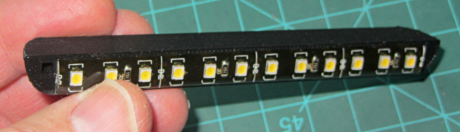
LED strip lights must have strain relief for their wires, as our Larval Engineer discovered the hard way on her longboard ground lighting project, and I wanted nice endcaps to avoid snagging on the fabric, so the general idea was a quarter-round rod with smooth endcaps and a hole to secure the wire. Some experiments showed that the acrylic (?) LED encapsulation directed the light downward, thus eliminating the need for a shade.
So, something like this will do for a first pass:
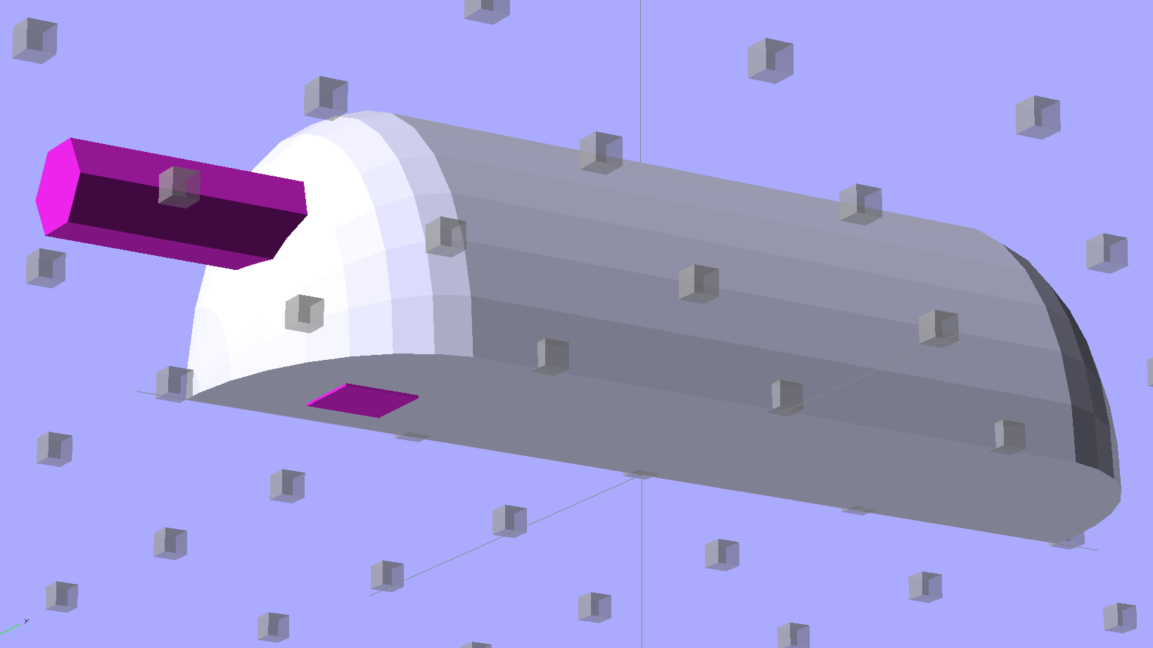
LED Strip Light Mount – bottom view
The overall dimensions for the LED mounts:
Length: N x 25 mm, plus endcap radii
Front-to-back width: 10 mm to allow for strip variation and 1 mm protection
Top-to-bottom height: 12 mm to fit double-sided foam sticky squares
Wire channels: 3 mm diameter or square cross-section
If there’s not enough light, I think a double-wide mount with two parallel LED strips would work.
After a bit of screwing around with additive endcaps that produced catastrophically non-manifold solid models, I figured out the proper subtractive way to build the mounts: the endcaps actually define the overall shape of the mount.
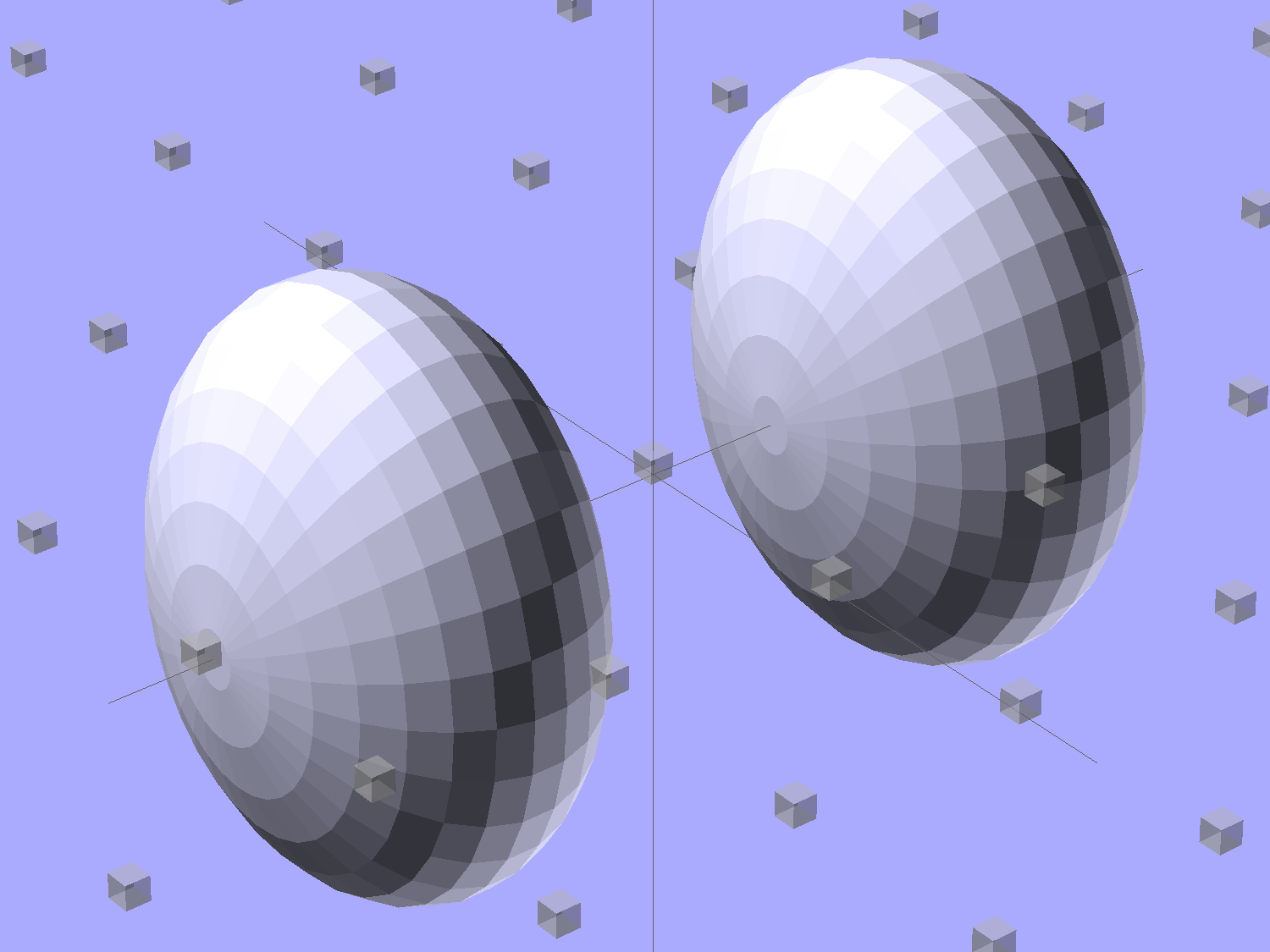
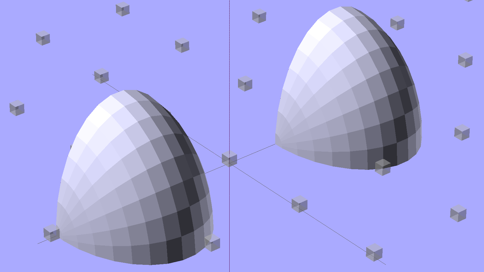
Start by placing a pair of spheroids, with radii matching the strip dimensions, so that their outer poles match the desired overall length:
Strip Light Mount – end cap spheroids – whole
The north/south poles must face outward, so that the equal-angle facets along the equators match up with what will become the mount body: rotate the spheroids 90° around the Y axis. The centers lie at the ends of the LED segments; the model shown here has a single 25 mm segment.
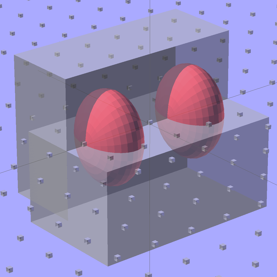
Then hack off three quadrants:
Strip Light Mount – end cap spheroids
That leaves two orange-segment shapes that define the endcaps:
Strip Light Mount – end caps – shaped
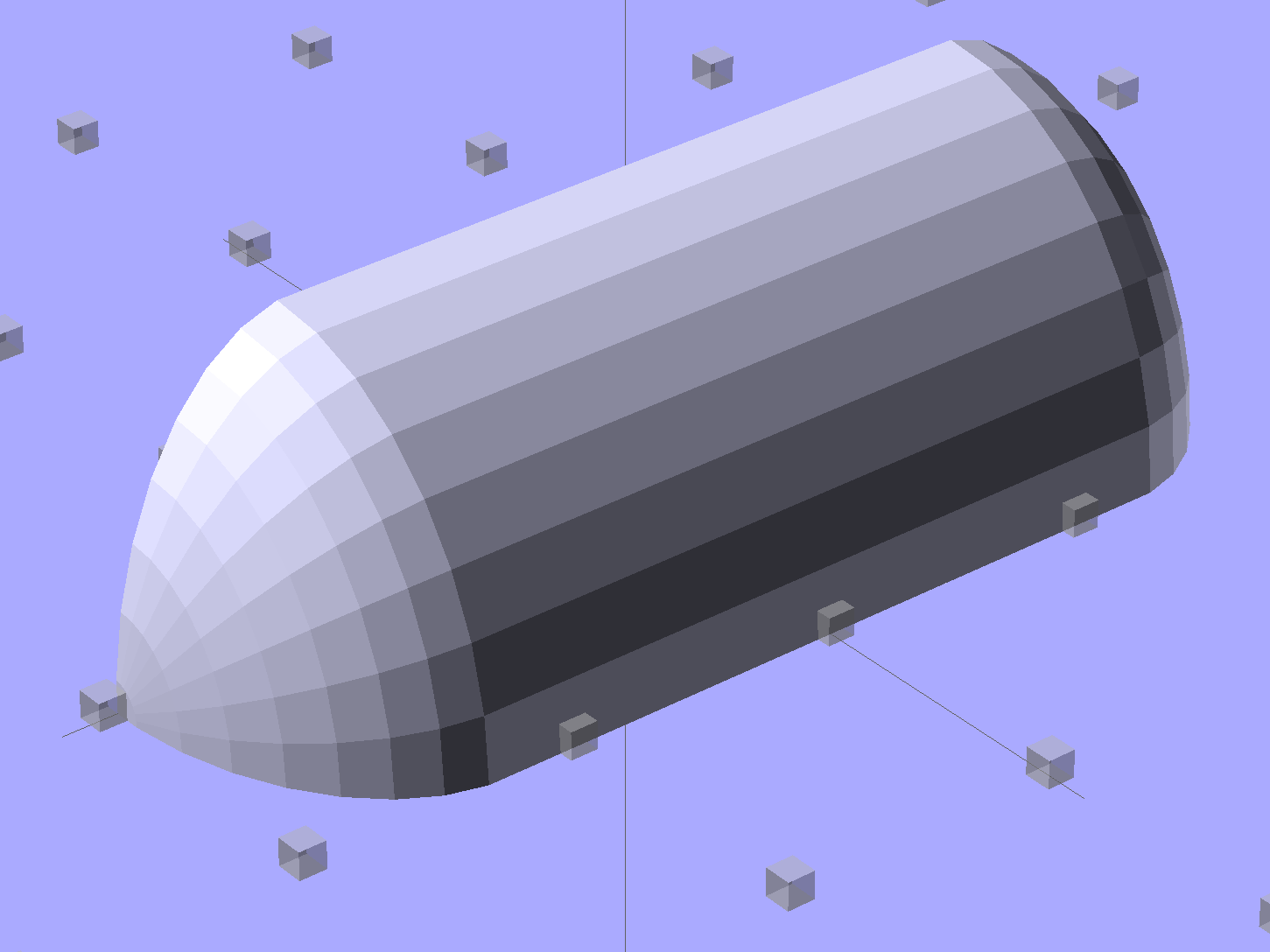
Here’s the key step that took me far too long to figure out. Shrinkwrapping the endcaps with the hull() function finesses the problem of matching the body facets to the endcap facets:
Strip Light Mount – end caps – hull
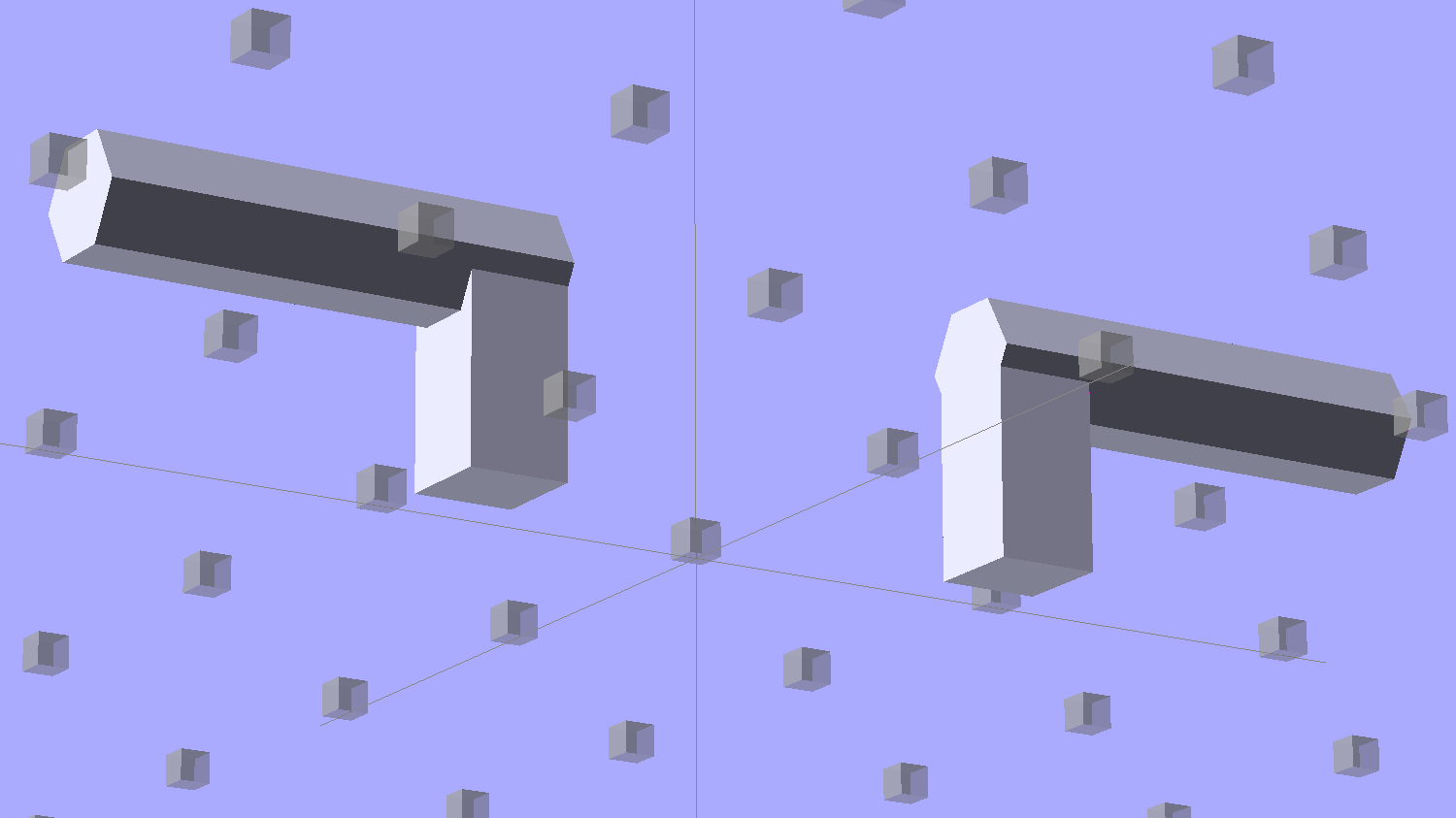
Model the wire channels as positive volumes that will be subtracted from the mount. The Channels layout shows both channels separated by a short distance:
Strip Light Mount – positive wire channels
The horizontal hexagons started as squares, but that looked hideous on the rounded endcaps.
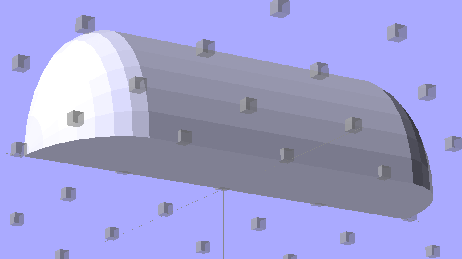
Seen from the bottom, the mount starts like this:
Strip Light Mount – no wiring channels
Position and subtract a wire channel:
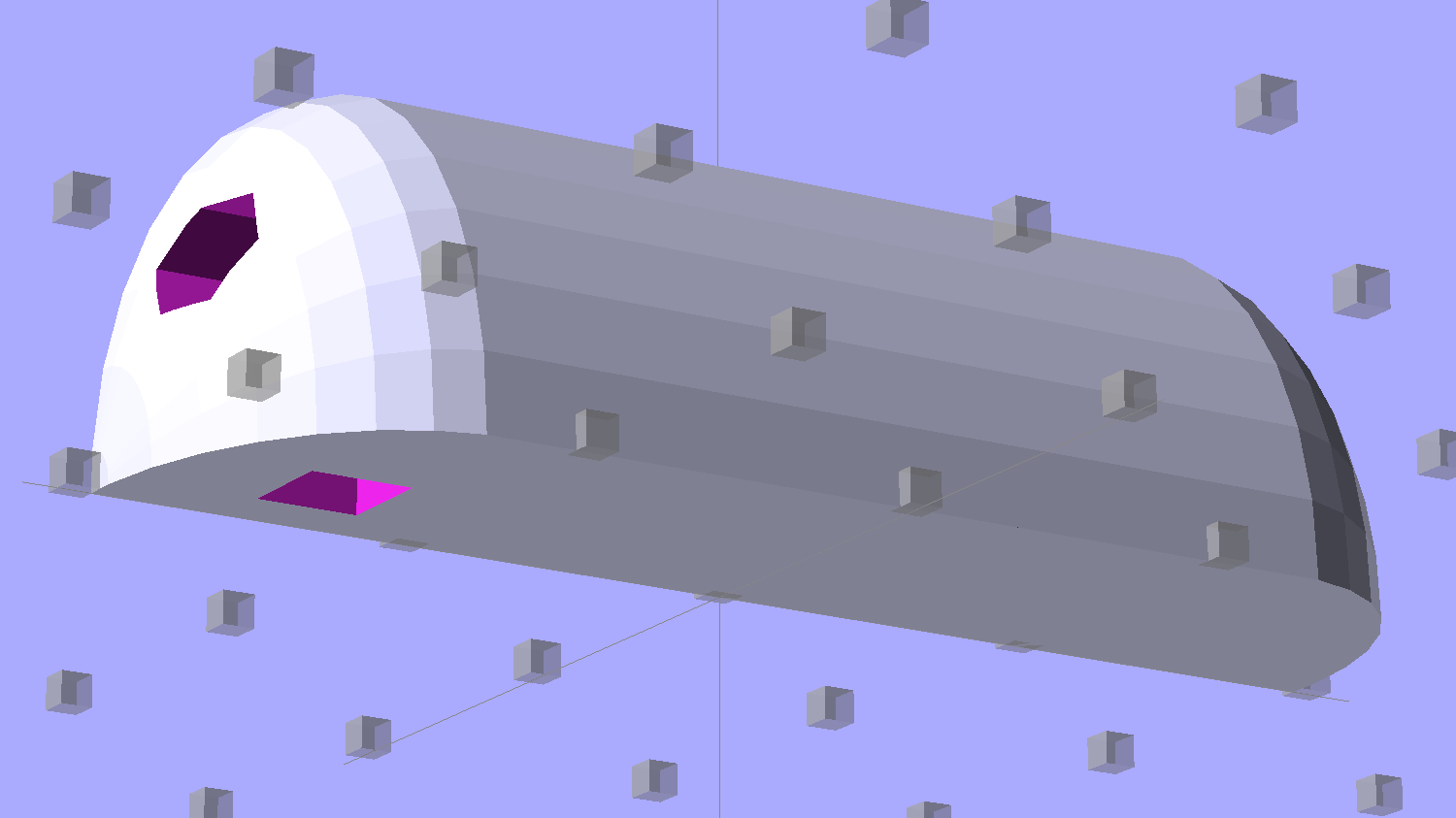
Strip Light Mount – visible wire channel
Which leaves the final solid model as a single, manifold object:
Strip Light Mount – complete
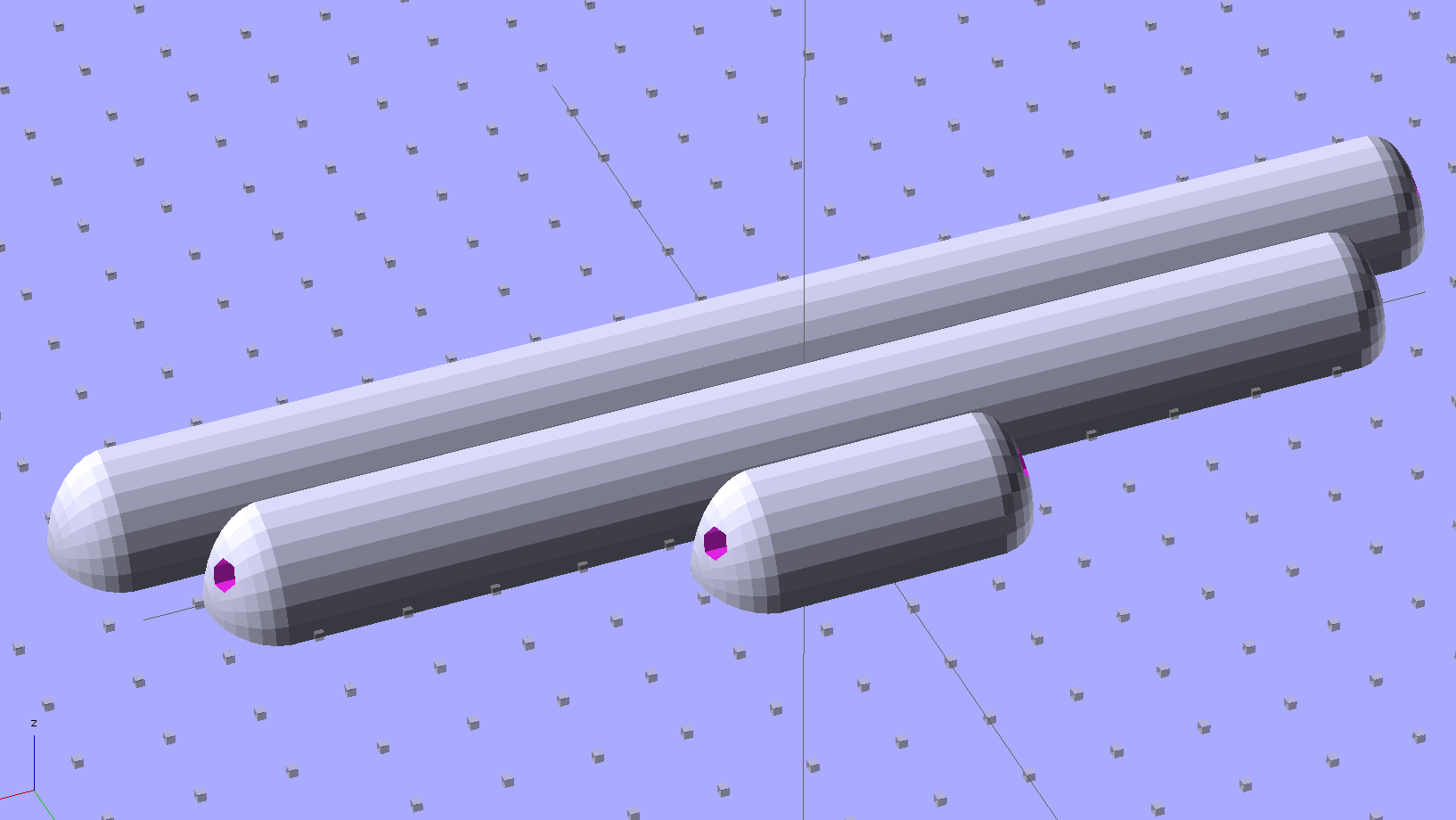
The module generating the mount takes three parameters: the number of LED segments and two string variables that determine whether to punch a channel in each endcap. Instantiate the module three times with suitable parameters to get a trio of LED mounts, all laid out for 3D printing:
Strip Light Mount – build layout
They built just exactly like those models would suggest; the M2 produces dependable results.
The OpenSCAD source code:
// LED Strip Lighting Brackets for Kenmore Model 158 Sewing Machine
// Ed Nisley - KE4ZNU - February 2014

Layout = "Strip";			// Build Show Channels Strip

//- Extrusion parameters must match reality!
//  Print with 2 shells and 3 solid layers

ThreadThick = 0.20;
ThreadWidth = 0.40;

HoleWindage = 0.2;			// extra clearance

Protrusion = 0.1;			// make holes end cleanly

AlignPinOD = 1.70;			// assembly alignment pins: filament dia

inch = 25.4;

function IntegerMultiple(Size,Unit) = Unit * ceil(Size / Unit);

//----------------------
// Dimensions

Segment = [25.0,10.0,3.0];		//  size of each LED segment

WireChannel = 3.0;				// wire routing channel

StripHeight = 12.0;				// sticky tape width
StripSides = 8*4;

DefaultLayout = [1,"Wire","NoWire"];

EndCap = [(2*WireChannel + 1.0),Segment[1],StripHeight];	// radii of end cap spheroid
EndCapSides = StripSides;

CapSpace = 2.0;						// build spacing for endcaps
BuildSpace = 1.5*Segment[1];		// spacing between objects on platform

//----------------------
// Useful routines

module PolyCyl(Dia,Height,ForceSides=0) {			// based on nophead's polyholes

  Sides = (ForceSides != 0) ? ForceSides : (ceil(Dia) + 2);

  FixDia = Dia / cos(180/Sides);

  cylinder(r=(FixDia + HoleWindage)/2,
           h=Height,
           $fn=Sides);
}

module ShowPegGrid(Space = 10.0,Size = 1.0) {

  RangeX = floor(100 / Space);
  RangeY = floor(125 / Space);

	for (x=[-RangeX:RangeX])
	  for (y=[-RangeY:RangeY])
		translate([x*Space,y*Space,Size/2])
		  %cube(Size,center=true);

}

//-- The negative space used to thread wires into the endcap

module MakeWireChannel(Which = "Left") {

	HalfSpace = EndCap[0] * ((Which == "Left") ? 1 : -1);

	render(convexity=2)
	translate([0,EndCap[1]/3,0])
		intersection() {
			union() {
				cube([2*WireChannel,WireChannel,EndCap[2]],center=true);
				translate([-2*EndCap[0],0,EndCap[2]/2])
					rotate([0,90,0]) rotate(180/6)
						PolyCyl(WireChannel,4*EndCap[0],6);
			}
			translate([HalfSpace,0,(EndCap[2] - Protrusion)]) {
				cube(2*EndCap,center=true);
			}
		}
}

//-- The whole strip, minus wiring channels

module MakeStrip(Layout = DefaultLayout) {

	BarLength = Layout[0] * Segment[0];				// central bar length

	hull()
		difference() {
			for (x = [-1,1])						// endcaps as spheroids
				translate([x*BarLength/2,0,0])
					resize(2*EndCap) rotate([0,90,0]) sphere(1.0,$fn=EndCapSides);
			translate([0,0,-EndCap[2]])
				cube([2*BarLength,3*EndCap[1],2*EndCap[2]],center=true);
			translate([0,-EndCap[1],0])
				cube([2*BarLength,2*EndCap[1],3*EndCap[2]],center=true);
		}

}

//-- Cut wiring channels out of strip

module MakeMount(Layout = DefaultLayout) {

	BarLength = Layout[0] * Segment[0];

	difference() {
		MakeStrip(Layout);
		if (Layout[1] == "Wire")
			translate([BarLength/2,0,0])
				MakeWireChannel("Left");
		if (Layout[2] == "Wire")
			translate([-BarLength/2,0,0])
				MakeWireChannel("Right");
	}
}

//- Build it

ShowPegGrid();

if (Layout == "Channels") {
	translate([ EndCap[0],0,0]) MakeWireChannel("Left");
	translate([-EndCap[0],0,0]) MakeWireChannel("Right");
}

if (Layout == "Strip") {
	MakeStrip(DefaultLayout);
}

if (Layout == "Show") {
	MakeMount(DefaultLayout);
}

if (Layout == "Build") {

	translate([0,BuildSpace,0]) MakeMount([1,"Wire","Wire"]);		// rear left side, vertical
	translate([0,0,0]) MakeMount([5,"Wire","NoWire"]);				// rear top, across arm
	translate([0,-BuildSpace,0]) MakeMount([6,"NoWire","Wire"]);	// front top, across arm
}
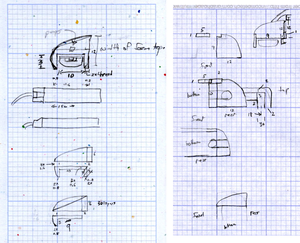
The original design doodles, which bear a vague resemblance to the final mounts:
LED Strip Light Mounts – Original Design Sketches
The little snood coming out of the top would hide a wire going through a hole drilled in the capital-S of “Sears” on the front panel, but I came to my senses long before implementing that idea…
Come to find out that Makerbot changed the spacing between the Y-axis rod and the idler bolt, so it doesn’t fit the TOM286. I could fire up the Token Windows Box, install Sketchup, modify the model, rebuild and clean up the STL, and try again, but it’s easier to just give up. The TOM286 has worked fine so far, so maybe this isn’t really needed.
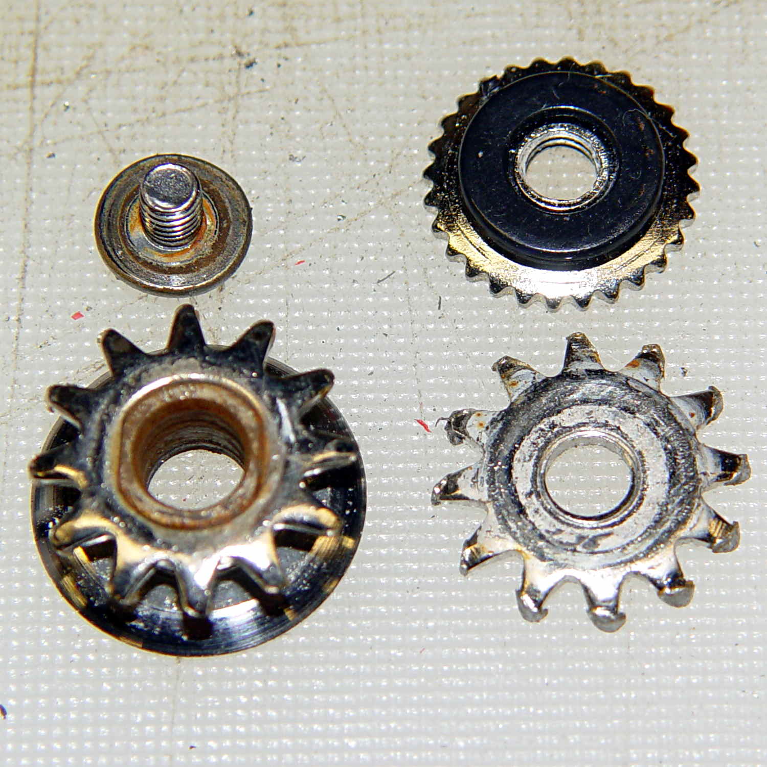
Cleaning up the wrecked gears on the can opener made it painfully obvious that I had to conjure at least one gear to get the poor thing working again:
Can opener – gears and cutters
Fortunately, those are more in the line of cogs, rather than real gears, so I decided a crude hack would suffice: drill a pattern of holes to define the openings between the teeth, file / grind the teeth reasonably smooth, and then tweak the shape to suit.
Fitting some small number-size drills between the remains of the teeth showed:
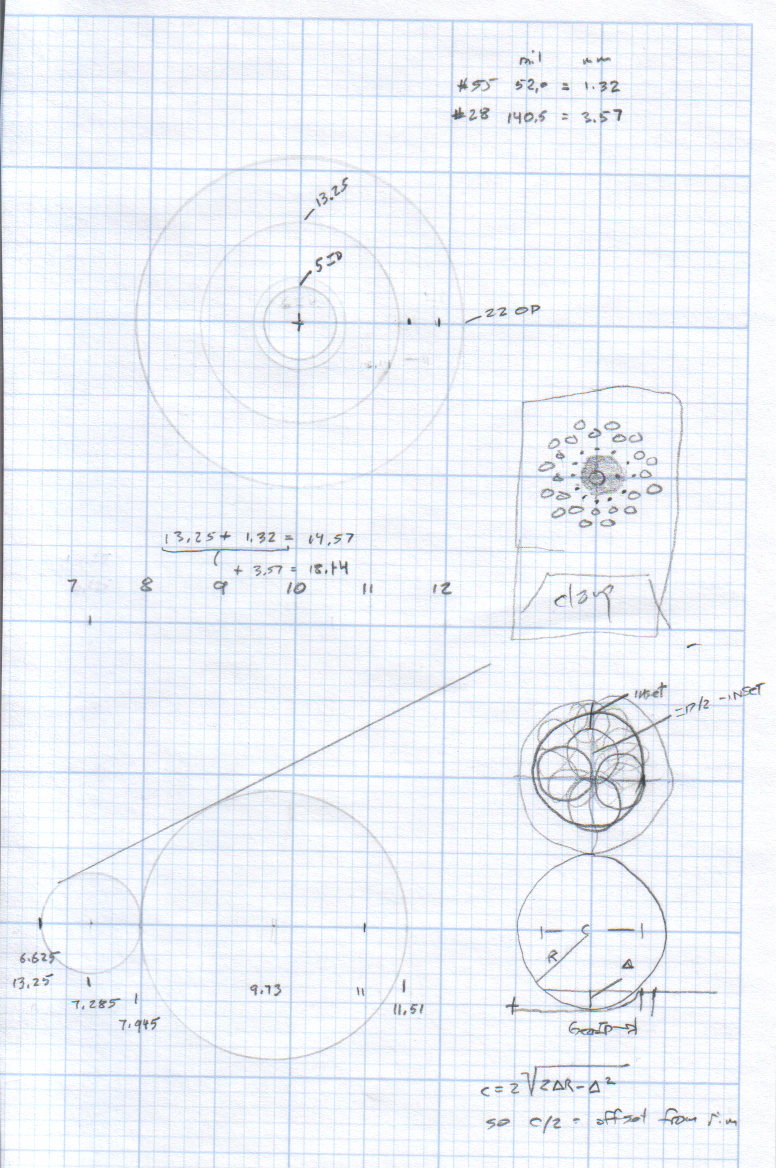
A #52 = 52.0 mil = 1.32 mm drill matched the root curvature
A #28 = 140.5 mil = 3.57 mm drill was tangent to the small drill and the tooth walls
Neither of those count as precision measurements, particularly given the ruined teeth, but they’re close enough for a first pass.
The OEM drive gear (on the right) has the teeth bent upward to mate with the cutter gear (on the left), but under normal gripping force, the teeth don’t mesh securely and tend to slide over / under / past each other. However, if I were to cut the drive gear from a metal sheet that’s thick enough to engage both the root and the crest of the cutter gear, that should prevent all the slipping & sliding. Some eyeballometric guesstimation suggested 2.5 mm would be about right and the Basement Laboratory Stockpile produced a small slab of 100 mil = 2.54 mm aluminum sheet.
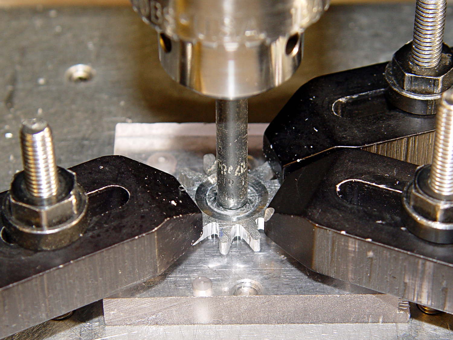
However, the center part of the gear must have the same thickness as the OEM gear to keep the drive wheel at the same position relative to the cutter blade, which means a bit of pocket milling. I have some small ball burrs that seemed like they might come in handy.
A recent thread on the LinuxCNC mailing list announced Bertho Stultien’s gcmc, the G-Code Meta Compiler, and this looked like a golden opportunity to try it out. Basically, gcmc lets you write G-Code programs in a C-like language that eliminates nearly all the horrendous syntactic noise of raw G-Code. I like it a lot and you’ll be seeing more of it around here…
The gcmc source code, down below, include a function that handles automatic tool height probing, using that simple white-goods switch. The literal() function emits whatever you hand it as text for the G-Code file, which is how you mechanize esoteric commands that gcmc doesn’t include in its repertoire. It’s basically the same as my bare G-Code probe routine, but now maintains a state variable that eliminates the need for separate first-probe and subsequent-probe entry points.
One point that tripped me up, even though I should know better: because gcmc is a compiler, it can’t read G-Code parameters that exist only when LinuxCNC (or whatever) is interpreting the G-Code. You can write parameters with values computed at compile time, but you can’t read and process them in the gcmc program.
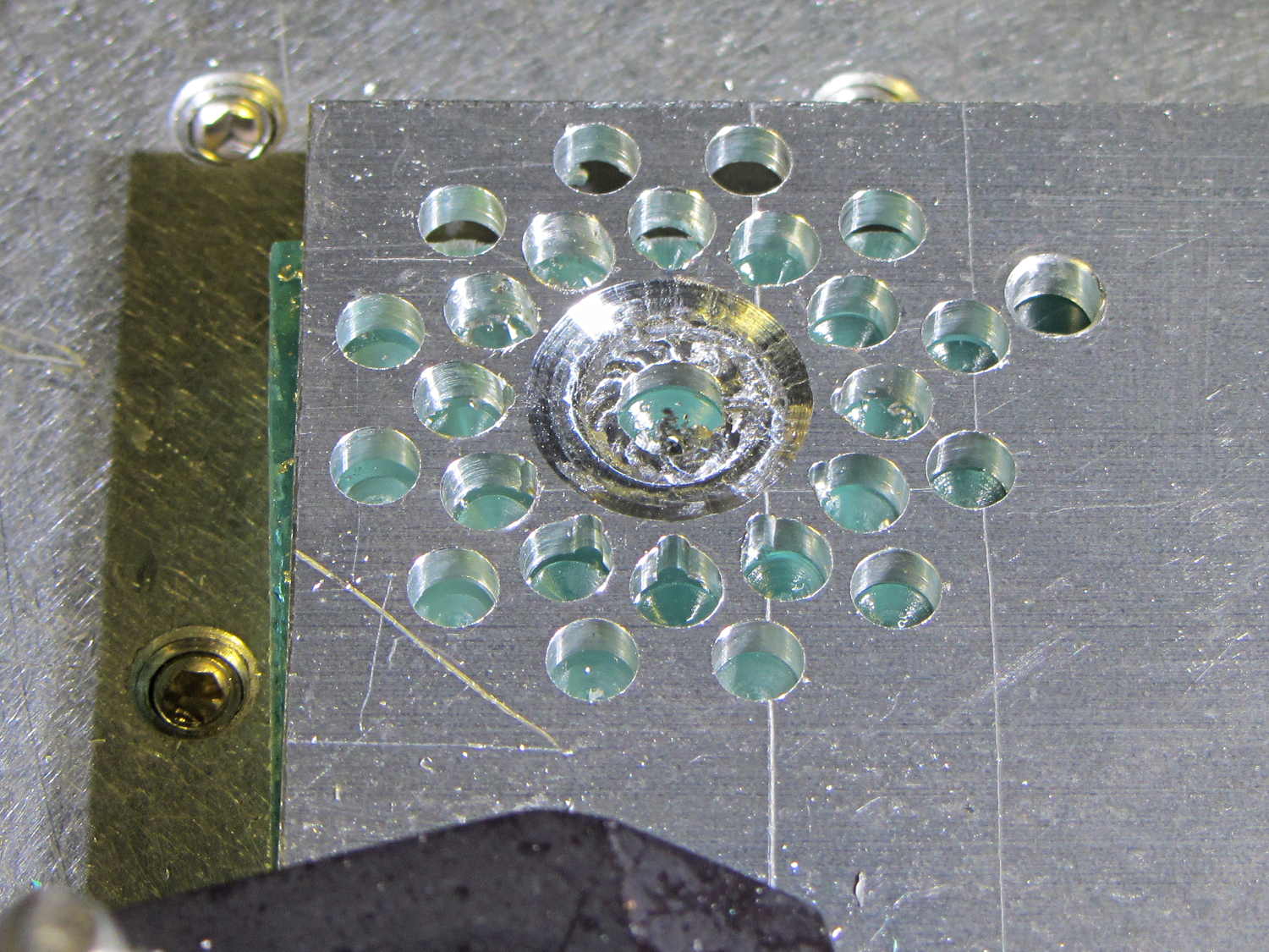
Anyhow, the first pass produced an array of holes that, as I fully expected, weren’t quite right:
Can opener gear – first hole pattern
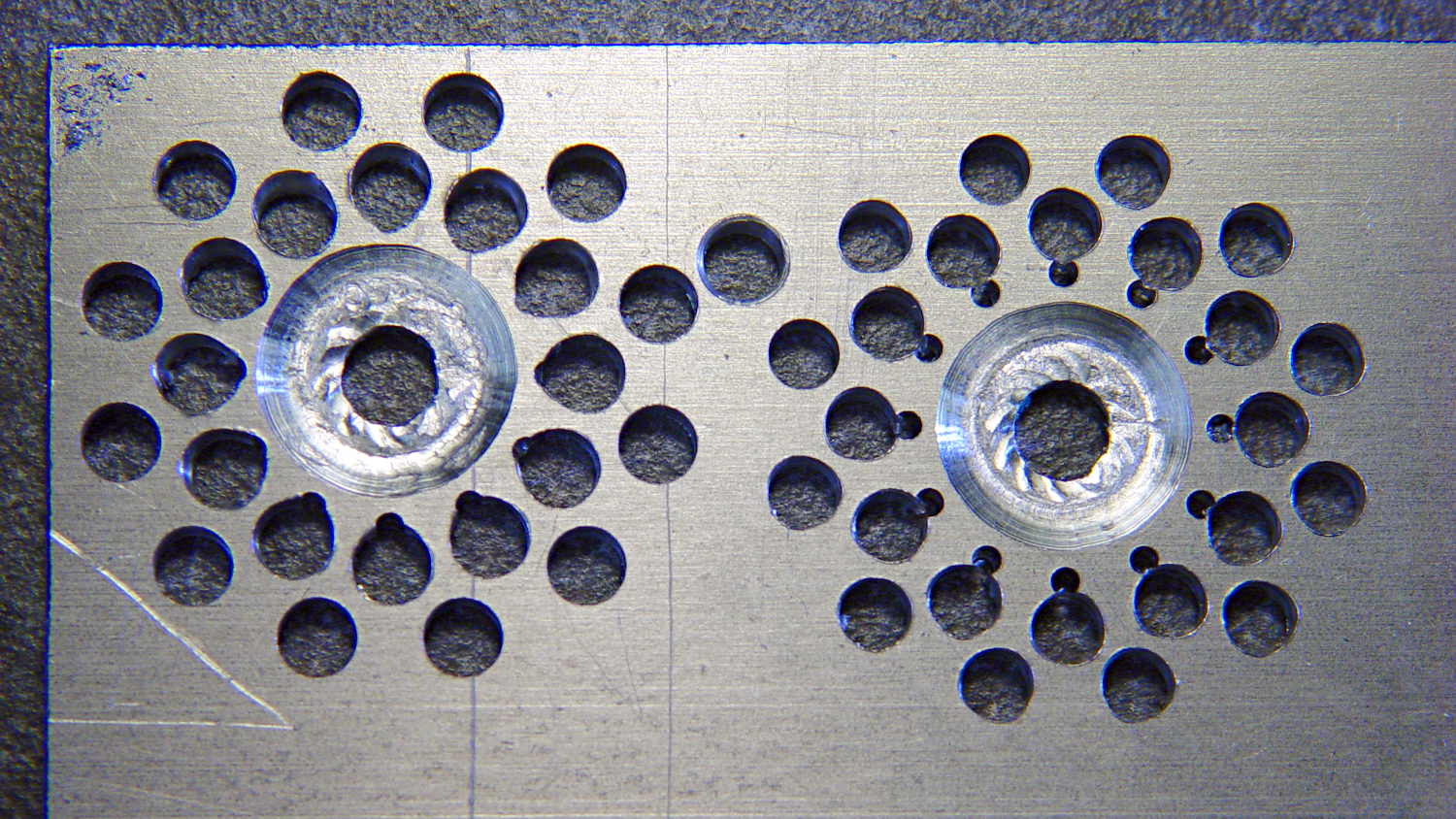
The second pass got the root and middle holes tangent to each other:
Can opener gear – second hole pattern
It also ran a center drill pass for those tiny little holes to prevent their drill from wandering about. The other drills are about the same size as the center drill, so they’re on their own.
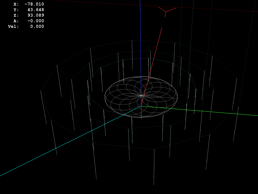
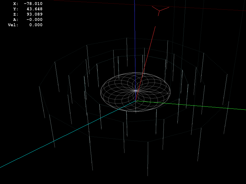
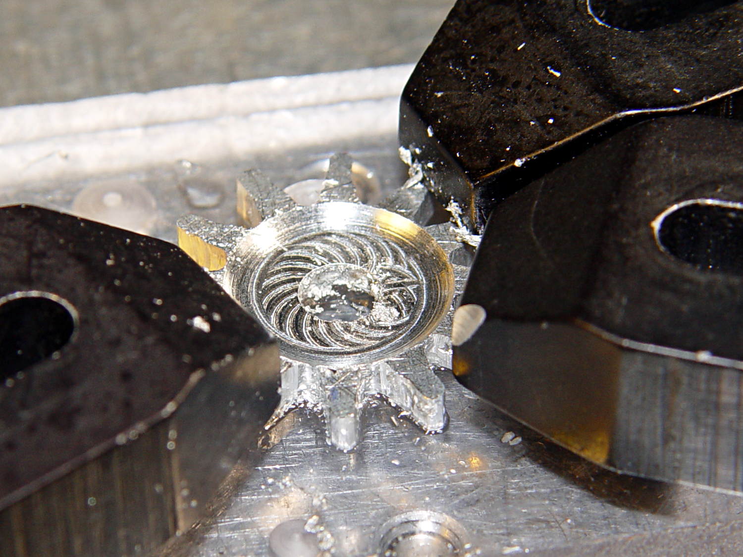
The rosette around the central hole comes from sweeping the burr in a dozen overlapping circles tangent to the outer diameter, then making a cleanup pass around the OD:
Can opener gear – 12 leaf rosette
Incidentally, that stray hole between the two patterns came from the aluminum sheet’s previous life, whatever it may have been. There are three other holes, two of which had flat washers taped to them, so your guess is as good as mine. That’s my story and I’m sticking with it.
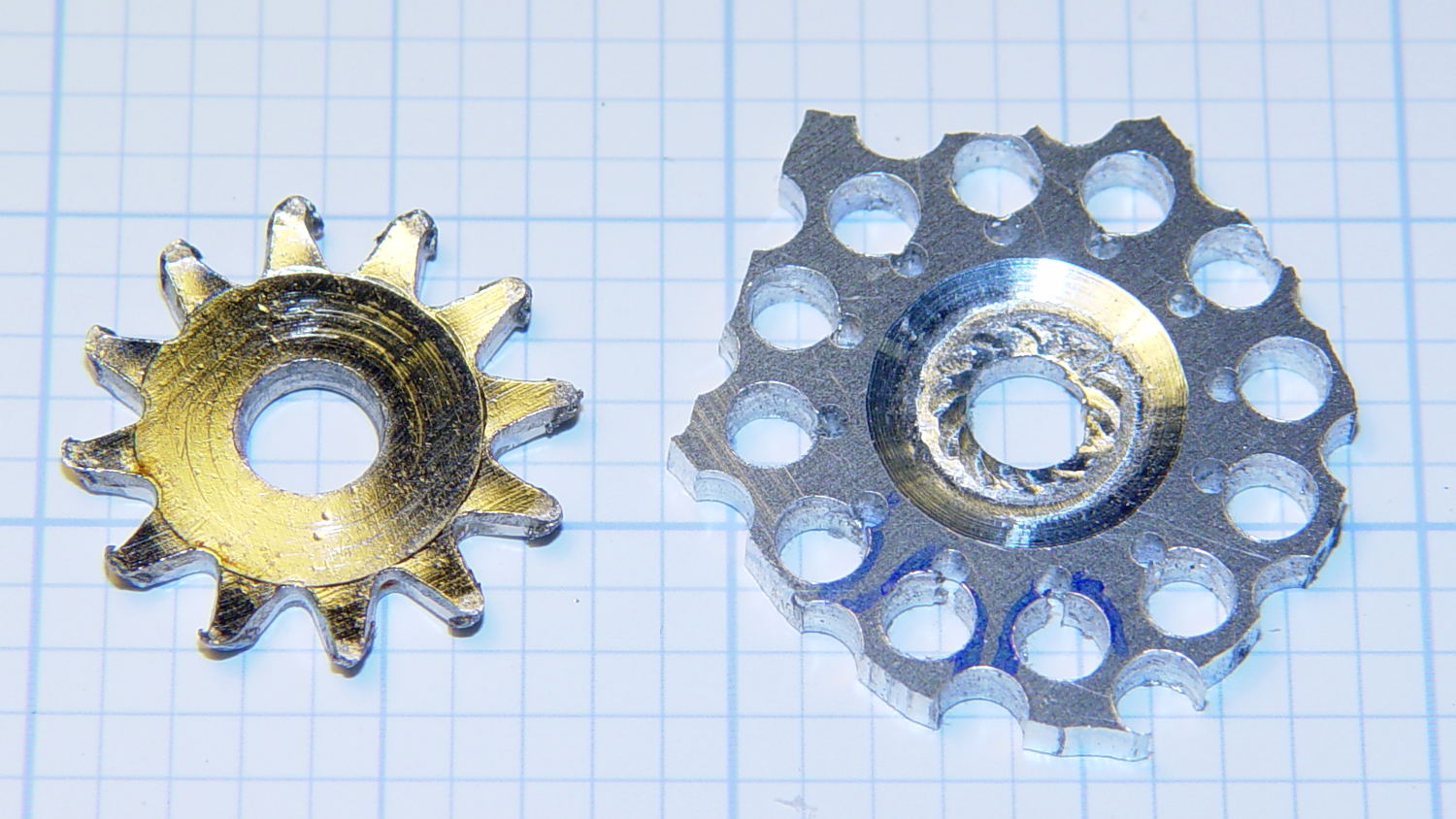
Introducing the sheet to Mr Bandsaw and cutting through the outer ring produced a bizarre snowflake:
Can opener gear – cut out
Cutting off the outer ring of holes turned the incipient gear body into a ragged shuriken:
Can opener gear – isolated
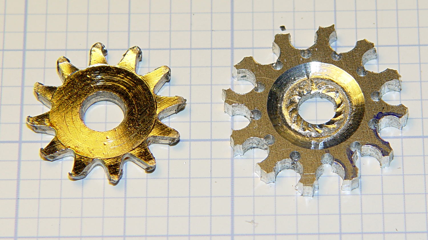
A few minutes of increasingly deft Dremel cutoff wheel work, poised on the bench vise over the shopvac nozzle to capture the dust, produced a credible gear shape:
Can opener gear – first pass
Iterating through some trial fits, re-grinds, and general fiddling showed that the center pocket was too shallow. The cutter wheel should slightly clear the drive wheel, but it’s an interference fit:
Can opener gear – trial fit
Which, of course, meant that I had to clamp the [mumble] thing back in the Sherline and re-mill the pocket. The trick is to impale it on the wrong end of a suitable drill, clamp it down, and touch off that spot as the origin:
Can opener gear – re-centering
I took the opportunity to switch to a smaller ball and make 16 little circles to clear the pocket:
Can Opener Gear – 16 leaf rosette
Now that’s better:
Can opener gear – deeper pocket
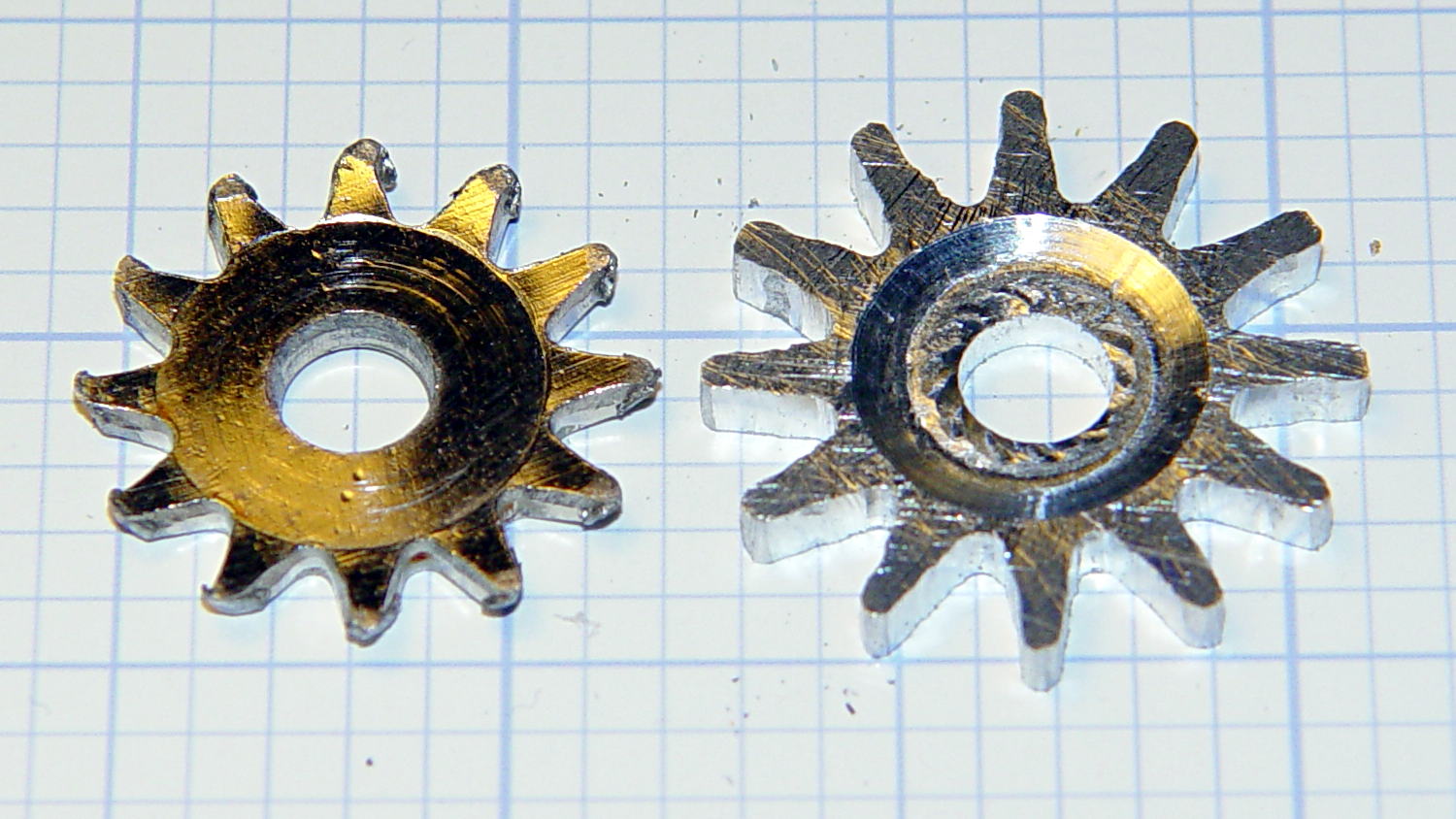
Another trial fit showed that everything ended up in the right place:
Can opener gear – final fit
I gave it a few cranks, touched up any cogs that clashed with the (still misshapen) cutter gear, applied it to a randomly chosen can, and it worked perfectly:
Squeeze the levers to easily punch through the lid
Crankety crank on the handle, while experiencing none of the previous drama
The severed lid falls into the can
Which is exactly how it’s supposed to work. What’s so hard about that?
What you can’t see in that picture is the crest of the lowest cutter gear tooth fitting just above the bottom of the drive gear root. Similarly, the crest of the highest drive gear tooth remains slightly above the cutter root. That means the cutter gear teeth always engage the drive gear, there’s no slipping & sliding, and it’s all good.
Aluminum isn’t the right material for a gear-like object meshed with a steel counterpart, but it’s easy to machine on a Sherline. I’ll run off a few more for show-n-tell and, if when this one fails, I’ll have backup.
The gcmc source code:
// Can opener drive gears
//	Ed Nisley KE4ZNU - February 2014
//	Sherline CNC mill with tool height probe
//	XYZ touchoff origin at center on fixture surface

DO_DRILLCENTER	= 1;
DO_MILLCENTER	= 1;
DO_DRILLINNER	= 1;
DO_DRILLOUTER	= 1;
DO_DRILLTIPS	= 1;

//----------
// Overall dimensions

GearThick = 2.54;			// overall gear thickness
GearCenterThick = 1.75;		// thickness of gear center

GearTeeth = 12;				// number of teeth!
ToothAngle = 360deg/GearTeeth;
GearOD = 22.0;				// tooth tip
GearID = 13.25;				// tooth root

SafeZ = 20.0;				// guaranteed to clear clamps
TravelZ = GearThick + 1.0;	// guaranteed to clear plate

//----------
// Tool height probe
//	Sets G43.1 tool offset in G-Code, so our Z=0 coordinate always indicates the touchoff position

ProbeInit = 0;					// 0 = not initialized, 1 = initialized
ProbeSpeed = 400.0mm;
ProbeRetract = 1.0mm;

PROBE_STAY = 0;					// remain at probe station
PROBE_RESTORE = 1;				// return to previous location after probe

function ProbeTool(RestorePos) {

local WhereWasI;

	WhereWasI = position();

	if (ProbeInit == 0) {		// probe with existing tool to set Z=0 as touched off
		ProbeInit++;
		literal("#<_Probe_Speed> = ",to_none(ProbeSpeed),"\n");
		literal("#<_Probe_Retract> = ",to_none(ProbeRetract),"\n");
		literal("#<_ToolRefZ> = 0.0 \t; prepare for first probe\n");
		ProbeTool(PROBE_STAY);
		literal("#<_ToolRefZ> = #5063 \t; save touchoff probe point\n");
		literal("G43.1 Z0.0 \t; set zero offset = initial touchoff\n");
	}
	elif (ProbeInit == 1) {		// probe with new tool, adjust offset accordingly
		literal("G49 \t; clear tool length comp\n");
		literal("G30 \t; move over probe switch\n");
		literal("G59.3 \t; use coord system 9\n");
		literal("G38.2 Z0 F#<_Probe_Speed> \t; trip switch on the way down\n");
		literal("G0 Z[#5063 + #<_Probe_Retract>] \t; back off the switch\n");
		literal("G38.2 Z0 F[#<_Probe_Speed> / 10] \t; trip switch slowly\n");
		literal("#<_ToolZ> = #5063 \t; save new tool length\n");
		literal("G43.1 Z[#<_ToolZ> - #<_ToolRefZ>] \t; set new length\n");
		literal("G54 \t; return to coord system 0\n");
		literal("G30 \t; return to safe level\n");
	}
	else {
		error("*** ProbeTool sees invalid ProbeInit: ",ProbeInit);
		comment("debug,*** ProbeTool sees invalid ProbeInit: ",ProbeInit);
		ProbeInit = 0;
	}

	if (RestorePos == PROBE_RESTORE) {
		goto(WhereWasI);
	}

}

//----------
// Utility functions

function WaitForContinue(MsgStr) {
	comment(MsgStr);
	pause();
}

function CueToolChange(MsgStr) {
	literal("G0 Z" + SafeZ + "\n");
	literal("G30\n");
	WaitForContinue(MsgStr);
}

function ToolChange(Info,Name) {
	CueToolChange("msg,Insert " + to_mm(Info[TOOL_DIA]) + " = " + to_in(Info[TOOL_DIA]) + " " + Name);
	ProbeTool(PROBE_STAY);

	WaitForContinue("msg,Set spindle to " + Info[TOOL_SPEED] + " rpm");
	feedrate(Info[TOOL_FEED]);
}

function GetAir() {
	goto([-,-,SafeZ]);
}

//-- compute drill speeds & feeds based on diameter
//		rule of thumb is 100 x diameter at 3000 rpm for real milling machines
//		my little Sherline's Z axis can't produce enough thrust for that!

MaxZFeed = 600.0mm;				// fastest possible Z feed

TOOL_DIA = 0;					// Indexes into DrillParam() result
TOOL_SPEED = 1;					//  spindle RPM
TOOL_FEED = 2;					//	linear feed
TOOL_TIP = 3;					//	length of 118 degreee drill tip

function DrillParam(Dia) {
local RPM,Feed,Tip,Data,Derating;

	Derating = 0.25;			// derate from (100 x diameter) max feed

	RPM = 3000.0;				// default 3 k rpm

	Feed = Derating * (100.0 * Dia);
	if (Feed > MaxZFeed) {
		RPM *= (MaxZFeed / Feed);	//  scale speed downward to fit
		Feed = MaxZFeed;
	}

	Tip = (Dia/2) * tan(90deg - 118deg/2);
	Data = [Dia,RPM,Feed,Tip];

	message("DrillParam: ",Data);
	return Data;
}

//-- peck drilling cycle

function PeckDrill(Endpt,Retract,Peck) {
	literal("G83 X",to_none(Endpt[0])," Y",to_none(Endpt[1])," Z",to_none(Endpt[2]),
			" R",to_none(Retract)," Q",to_none(Peck),"\n");
}

//----------
// Make it happen

literal("G99\t;  retract to R level, not previous Z\n");

WaitForContinue("msg,Verify: G30 position in G54 above tool change switch?");

WaitForContinue("msg,Verify: fixture origin XY touched off at center of gear?");

WaitForContinue("msg,Verify: Z touched off on top surface at " + GearThick + "?");
ProbeTool(PROBE_STAY);

//-- Drill center hole

if (DO_DRILLCENTER) {

	DrillData = DrillParam(5.0mm);
	ToolChange(DrillData,"drill");

	goto([0,0,-]);
	goto([-,-,TravelZ]);

	drill([0,0,-1.5*DrillData[TOOL_TIP]],TravelZ,DrillData[TOOL_DIA]);
	GetAir();

}

//-- Drill inner ring

if (DO_DRILLINNER) {

	DrillData = DrillParam(1.32mm);

	RingRadius = GearID/2.0 + DrillData[TOOL_DIA]/2.0;		// center of inner ring holes
	HolePosition = [RingRadius,0mm,-1.5*DrillData[TOOL_TIP]];

//	but first, center-drill to prevent drifting

	CDData = DrillParam(1.00mm);			// pretend it's a little drill
	CDData[TOOL_FEED] = 100mm;				//  ... use faster feed

	CDPosition = HolePosition;				// use center drill coordinates
	CDPosition[2] = GearThick - 0.25mm;		//  ... just below surface

	ToolChange(CDData,"center drill");

	goto([0,0,-]);
	goto([-,-,TravelZ]);

	for (Tooth = 0 ; Tooth < GearTeeth ; Tooth++) {
		drill(CDPosition,TravelZ,2*TravelZ);		// large increment ensures one stroke
		CDPosition = rotate_xy(CDPosition,ToothAngle);
	}

//	now drill the holes

	ToolChange(DrillData,"drill");

	goto([0,0,-]);
	goto([-,-,TravelZ]);

	for (Tooth = 0 ; Tooth < GearTeeth ; Tooth++) {
		PeckDrill(HolePosition,TravelZ,DrillData[TOOL_DIA]);
		HolePosition = rotate_xy(HolePosition,ToothAngle);
	}

	GetAir();

}

//-- Mill center recess

if (DO_MILLCENTER) {

	MillData = [4.50mm,3000,250.0mm,0.0mm];			// spherical ball burr

	Delta = GearThick - GearCenterThick;							// depth to be milled away
	Inset = sqrt(2.0*Delta*(MillData[TOOL_DIA]/2) - pow(Delta,2));	// toll axis to milled edge

	ToolChange(MillData,"ball burr");

	goto([0,0,-]);							// above central hole
	goto([0,0,GearThick]);					// vertically down to flush with surface
	move([0,0,GearCenterThick]);			// into gear blank

	for (Angle = 0.0deg; Angle < 360.0deg; Angle+=360.0deg/16) {	// clear interior
		circle_cw((GearID/2 - Inset)/2,Angle);
	}

	move_r([(GearID/2 - Inset),0.0,0.0]);							// clean rim
	circle_ccw([0.0,0.0,GearCenterThick],2);

	GetAir();

}

//-- Drill outer ring

if (DO_DRILLOUTER) {

	RingRadius += DrillData[TOOL_DIA]/2;		// at OD of inner ring holes

	DrillData = DrillParam(3.18mm);
	RingRadius += DrillData[TOOL_DIA]/2.0;		// center of outer ring holes
	HolePosition = [RingRadius,0mm,-1.5*DrillData[TOOL_TIP]];

	ToolChange(DrillData,"drill");

	for (Tooth = 0 ; Tooth < GearTeeth ; Tooth++) {
		PeckDrill(HolePosition,TravelZ,DrillData[TOOL_DIA]);
		HolePosition = rotate_xy(HolePosition,ToothAngle);
	}

	GetAir();

}

//-- Drill to locate gear tooth tip end

if (DO_DRILLTIPS) {

	DrillData = DrillParam(4.22mm);

	RingRadius = GearOD/2.0 + DrillData[TOOL_DIA]/2.0;		// tangent to gear tooth tip
	HolePosition = [RingRadius,0mm,-1.5*DrillData[TOOL_TIP]];
	HolePosition = rotate_xy(HolePosition,ToothAngle/2);	// align to tooth

	ToolChange(DrillData,"drill");

	for (Tooth = 0 ; Tooth < GearTeeth ; Tooth++) {
		PeckDrill(HolePosition,TravelZ,DrillData[TOOL_DIA]);
		HolePosition = rotate_xy(HolePosition,ToothAngle);
	}

	GetAir();

}

literal("G30\n");
comment("msg,Done!");
The original doodle that suggested the possibility:
Can Opener Gears – Doodle 1
The chord equation at the bottom shows how to calculate the offset for the ball burr, although it turns out there’s no good way to measure the cutting diameter of the burr and it’s not really spherical anyway.
A more detailed doodle with the key line at a totally bogus angle:
Can Opener Gears – Doodle 2
The diagram in the lower right corner shows how you figure the length of the tip on a 118° drill point, which you add to the thickness of the plate in order to get a clean hole.
The first convert normalizes the grayscale file and produces a PNG file in a standard format.
The next two convert operations translate that PNG file into uncompressed PGM files with the data as ASCII text required by OpenSCAD’s surface() function. It’s not in the proper format, however, so a few lines of Bash-fu rearrange the data into DAT files; the extension is arbitrary.
Then OpenSCAD eats those files along with a bunch of configuration settings and spits out a solid model of the positive mold in STL format.
The MakePositive.scad OpenSCAD source code:
// Mold positive pattern from grayscale height map using Minkowski sum
// Ed Nisley KE4ZNU - February 2014 - adapted from cookie press, added alignment pins

//-----------------
// Mold files

fnMap = "SqWr_map.dat";					// override with -D 'fnMap="whatever.dat"'
fnPlate = "SqWr_plate.dat";				// override with -D 'fnPlate="whatever.dat"'

DotsPerMM = 3.0;						// overrride with -D DotsPerMM=number

MapHeight = 5.0;						// overrride with -D MapHeight=number

ImageX = 100;							// overrride with -D ImageX=whatever
ImageY = 100;

MapScaleXYZ = [1/DotsPerMM,1/DotsPerMM,MapHeight/255];
PlateScaleXYZ = [1/DotsPerMM,1/DotsPerMM,1.0];

echo("Press File: ",fnMap);
echo("Plate File: ",fnPlate);

echo(str("ImageX:",ImageX," ImageY: ", ImageY));
echo(str("Map Height: ",MapHeight));
echo(str("Dots/mm: ",DotsPerMM));
echo(str("Scale Map: ",MapScaleXYZ,"  Plate: ",PlateScaleXYZ));

//- Extrusion parameters - must match reality!

ThreadThick = 0.25;
ThreadWidth = 2.0 * ThreadThick;

//- Buid parameters

PlateThick = IntegerMultiple(1.0,ThreadThick);		// solid plate under press relief

PinOD = 1.75;				// locating pin diameter
PinDepth = PlateThick;		//  ... depth into bottom surface = total length/2
PinOC = 20.0;				// spacing within mold item

echo(str("Pin depth: ",PinDepth," spacing: ",PinOC));

//- Useful info

function IntegerMultiple(Size,Unit) = Unit * ceil(Size / Unit);

HoleWindage = 0.2;

Protrusion = 0.1;						// make holes & unions work correctly

MaxConvexity = 5;						// used for F5 previews in OpenSCAD GUI

ZFuzz = 0.2;							// numeric chaff just above height map Z=0 plane

//-----------------
// Import plate height map, slice off a slab to define outline

module Slab(Thick=1.0) {
	intersection() {
		translate([0,0,Thick/2])
			cube([2*ImageX,2*ImageY,Thick],center=true);
		scale(PlateScaleXYZ)
			difference() {
				translate([0,0,-ZFuzz])
					surface(fnPlate,center=true,convexity=MaxConvexity);
				translate([0,0,-1])
					cube([2*ImageX,2*ImageY,2],center=true);
			}
	}
}

//- Put peg grid on build surface

module ShowPegGrid(Space = 10.0,Size = 1.0) {

	Range = floor(50 / Space);

	for (x=[-Range:Range])
	  for (y=[-Range:Range])
		translate([x*Space,y*Space,Size/2])
			%cube(Size,center=true);
}

//-- convert cylinder to low-count polygon

module PolyCyl(Dia,Height,ForceSides=0) {			// based on nophead's polyholes

  Sides = (ForceSides != 0) ? ForceSides : (ceil(Dia) + 2);

  FixDia = Dia / cos(180/Sides);

  cylinder(r=(FixDia + HoleWindage)/2,
           h=Height,
	   $fn=Sides);
}

//-- Locating pin hole with glue recess
//  Default length is two pin diameters on each side of the split

module LocatingPin(Dia=PinOD,Len=0.0) {

	PinLen = (Len != 0.0) ? Len : (4*Dia);

	translate([0,0,-ThreadThick])
		PolyCyl((Dia + 2*ThreadWidth),2*ThreadThick,4);

	translate([0,0,-2*ThreadThick])
		PolyCyl((Dia + 1*ThreadWidth),4*ThreadThick,4);

	translate([0,0,-(Len/2 + ThreadThick)])
		PolyCyl(Dia,(Len + 2*ThreadThick),4);

}

//- Build it

//ShowPegGrid();

echo("Building mold");
union() {
	difference() {
		Slab(PlateThick + Protrusion);
		for (i=[-1,1])
			translate([0,i*PinOC/2,0])
				rotate(180/4) LocatingPin(Len=2*PinDepth);
	}
	translate([0,0,PlateThick])							// cookie press height map
		scale(MapScaleXYZ)
		difference() {
			translate([0,0,-ZFuzz])
				surface(fnMap,center=true,convexity=MaxConvexity);
			translate([0,0,-1])
				cube([2*ImageX,2*ImageY,2],center=true);
		}
}
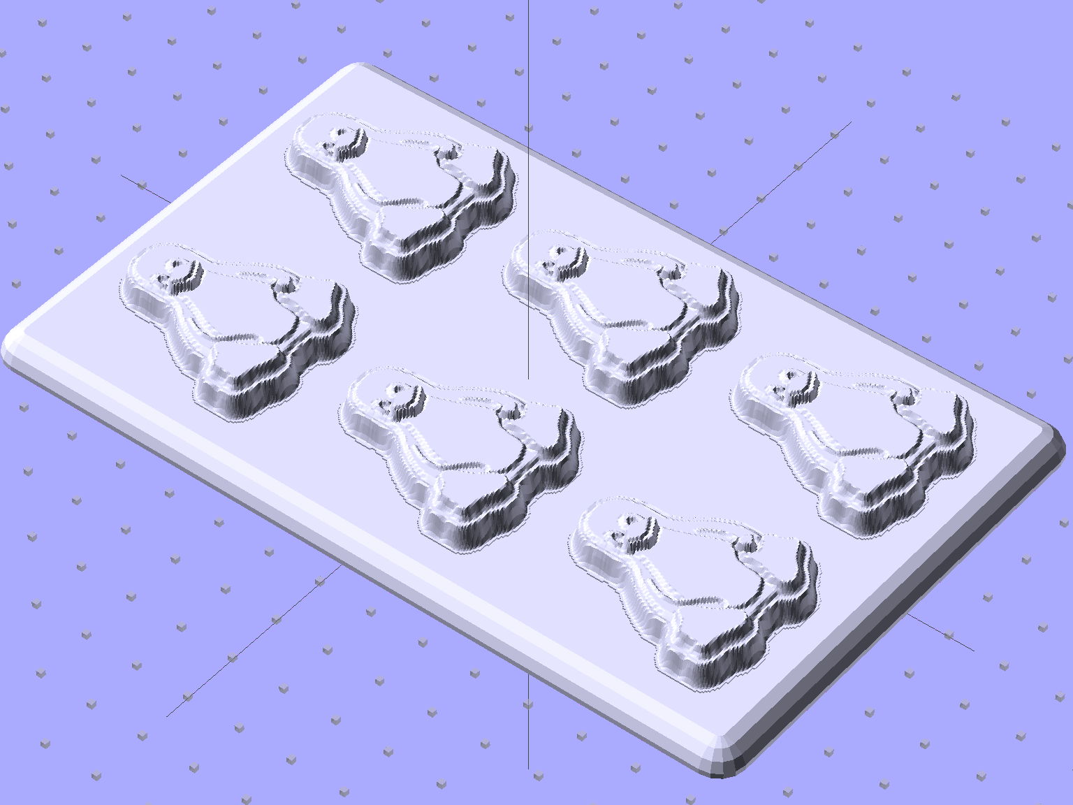
The plate holds the molds in place, perhaps with tapeless sticky, while you’re slathering silicone goop to make the negative mold:
Tux Positive Mold Framework – 2×3 array
As you might expect, the OpenSCAD file that generates the plate-with-holes can also embed the positive molds atop the plate, so you could get a solid (well, infilled at 20%) chunk of plastic without attaching the molds. I’d rather do the plate separately from the molds, so you can recycle the plate for many different molds. Your mileage may vary.
The Positive Mold Framework.scad OpenSCAD source code:
// Positive mold framework for chocolate slabs
// Ed Nisley - KE4ZNU - January 2014

Layout = "FramePins";		// FramePins FrameMolds Pin

//- Extrusion parameters must match reality!
//  Print with 2 shells and 3 solid layers

ThreadThick = 0.20;
ThreadWidth = 0.40;

Protrusion = 0.1;			// make holes end cleanly

HoleWindage = 0.2;

//----------------------
// Dimensions

FileName = "Tux-positive.stl";	// overrride with -D

Molds = [2,3];					// count of molds within framework

MoldOC = [40.0,45.0];			// on-center spacing of molds
MoldSlab = 1.0;					// thickness of slab under molds

BaseThick = 5.0;

BaseSize = [(Molds[0]*MoldOC[0] + 0),(Molds[1]*MoldOC[1] + 0),BaseThick];
echo(str("Overall base: ",BaseSize));

PinOD = 1.75;					// locating pin diameter
PinLength = 2.0;				//  ... total length
PinOC = 20.0;				// spacing within mold item

//----------------------
// Useful routines

//- Put peg grid on build surface

module ShowPegGrid(Space = 10.0,Size = 1.0) {

	RangeX = floor(100 / Space);
	RangeY = floor(125 / Space);

	for (x=[-RangeX:RangeX])
		for (y=[-RangeY:RangeY])
			translate([x*Space,y*Space,Size/2])
			%cube(Size,center=true);

}

module PolyCyl(Dia,Height,ForceSides=0) {			// based on nophead's polyholes

  Sides = (ForceSides != 0) ? ForceSides : (ceil(Dia) + 2);

  FixDia = Dia / cos(180/Sides);

  cylinder(r=(FixDia + HoleWindage)/2,
           h=Height,
	   $fn=Sides);
}

// Locating pin hole with glue recess
//  Default length is two pin diameters on each side of the split

module LocatingPin(Dia=PinOD,Len=0.0) {

	PinLen = (Len != 0.0) ? Len : (4*Dia);

	translate([0,0,-ThreadThick])
		PolyCyl((Dia + 2*ThreadWidth),2*ThreadThick,4);

	translate([0,0,-2*ThreadThick])
		PolyCyl((Dia + 1*ThreadWidth),4*ThreadThick,4);

	translate([0,0,-(Len/2 + ThreadThick)])
		PolyCyl(Dia,(Len + 2*ThreadThick),4);

}

module LocatingPins(Length) {
	for (i=[-1,1])
	translate([0,i*PinOC/2,0])
		rotate(180/4)
		LocatingPin(Len=Length);
}

//-- import a single mold item

module MoldItem() {
	import(FileName,convexity=10);
}

//-- Overall frame shape

module Frame() {

//	translate([0,0,BaseSize[2]/2])		// platform under molds
//		cube(BaseSize,center=true);

	difference() {
		hull()
			for (i=[-1,1], j=[-1,1])
				translate([i*BaseSize[0]/2,j*BaseSize[1]/2,0])
					sphere(r=BaseThick);
		translate([0,0,-BaseThick])
			cube(2*BaseSize,center=true);
	}

}

//- Build it

ShowPegGrid();

if (Layout == "Pin")
	LocatingPin(Len=PinLength);

if (Layout == "Frame")
	Frame();

if (Layout == "FramePins")
	difference() {
		Frame();

		translate([-MoldOC[0]*(Molds[0] - 1)/2,-MoldOC[1]*(Molds[1] - 1)/2,0])
			for (i=[0:Molds[0]-1],j=[0:Molds[1]-1])
				translate([i*MoldOC[0],j*MoldOC[1],BaseSize[2]])
					LocatingPins(BaseThick);
	}

if (Layout == "FrameMolds") {
	Frame();
	translate([-MoldOC[0]*(Molds[0] - 1)/2,-MoldOC[1]*(Molds[1] - 1)/2,0])
		for (i=[0:Molds[0]-1],j=[0:Molds[1]-1])
			translate([i*MoldOC[0],j*MoldOC[1],BaseThick - MoldSlab + Protrusion])
			MoldItem();
}
And then it’s time to pour some chocolate… which someone else knows how to do much better than I!
I picked a 3.0 pixel/mm scale factor, so a 33 mm mold covers only 100 pixels. That image is 1100 mm tall and will be reduced by a factor of 10 to the final image size: this is not the place for fine detail and fancy lettering!
The conversion process assumes you’ll handle the Z axis scaling yourself, so the script no longer normalizes the gray levels. If you select gray levels using HSV, the V slider gives you a direct reading in percent-of-maximum thickness; Tux varies from V = 80 to 100, so he’s pretty much bas relief.
The border around the image must be 0 = black and will be stripped from the final mold. That’s why Tux doesn’t turn into a bird served on a rectangular platter.
Because this is a mold, its edges must have some draft, which means the outline must shade from black to whatever gray represents the interior of the mold. Do this:
Trace the outline using the Scissors Select tool = snap to high-contrast outer edge
Create / go to a new layer filled with whatever gray you want for the interior (V = 80 here)
Select → Grow the selection by 60 pixels (on a 1000×1100 image)
Select → Invert to select the exterior of the outline
Bucket fill the exterior with 0 = black
Select → Invert to select the interior of the outline again
Select → Border: Add a 30 pixel border to the selection with the “Feather border” option
Bucket fill the border with 0 = black
Unselect and you have a layer with a nice graduation around the mold
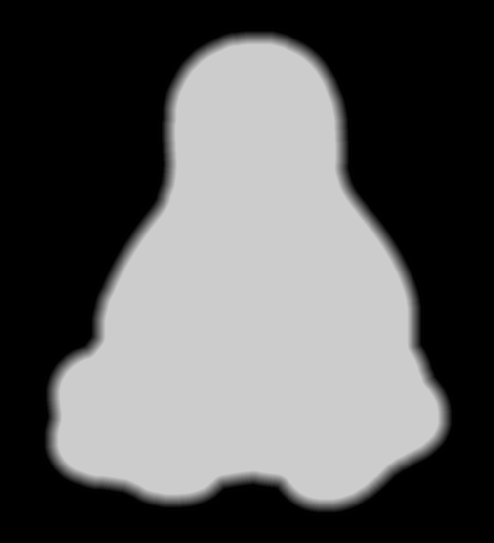
Which looks like this with V=80 gray inside:
Tux Mold – Height Map – outline gradient
The 30 pixel feathered border, scaled by the 10× reduction, means the edge of the mold goes from 0 = black to the interior in about 3 pixel / (3 pixel/mm) = 1 mm. If the interior is 255 = white at 7 mm, the draft angle is arctan 1/7 = 8°, which is probably about right for the deepest part of the mold. The edge of the Tux mold is V = 80 (or about 200 gray), so it’s at 0.8 × 7 mm = 5.6 mm and the draft angle is arctan 1/5.6 = 10°.
Inside the mold, anything goes, but you should avoid 0 = black levels so that the alignment pins don’t poke through the mold. Any 255 = 100 V = white levels will be the maximum mold thickness, which is 7 mm for the molds you see here and that may be somewhat too thick for a chocolate treat. It is really hard to maintain draft on small features, but I think if you don’t get carried away it’ll be all good.
There’s also a 1 mm backing plate below the mold that ensures the deepest mold parts have some substance behind them and the alignment pin sockets have enough depth to be useful.
Scaling the image down by 10× to about 110 pixels tall (including the black border) will make the final Tux mold about 37 mm tall:
Tux
This image enlarges it by 10× with no smoothing to show the gritty nature of the image. This is why you can’t have delicate detail or fine lettering:
Tux – enlarged to show texture
Notice the nearly complete lack of draft on the interior features. Each level differs by about V = 5 over the range V = 80(the border) to V = 100 (beak and flipper), so they amount to only 0.05 × 7 mm = 0.35 mm = one or two thread layers at 0.20 mm/layer. I think if you were doing this right, you’d pick an overall thickness so that V = 5 increments corresponded to one layer or use whatever V increments corresponded to a single layer.
Running that image through the Bash script & OpenSCAD programs (more on those later) produces a reasonable result:
Tux positive mold – solid model – oblique
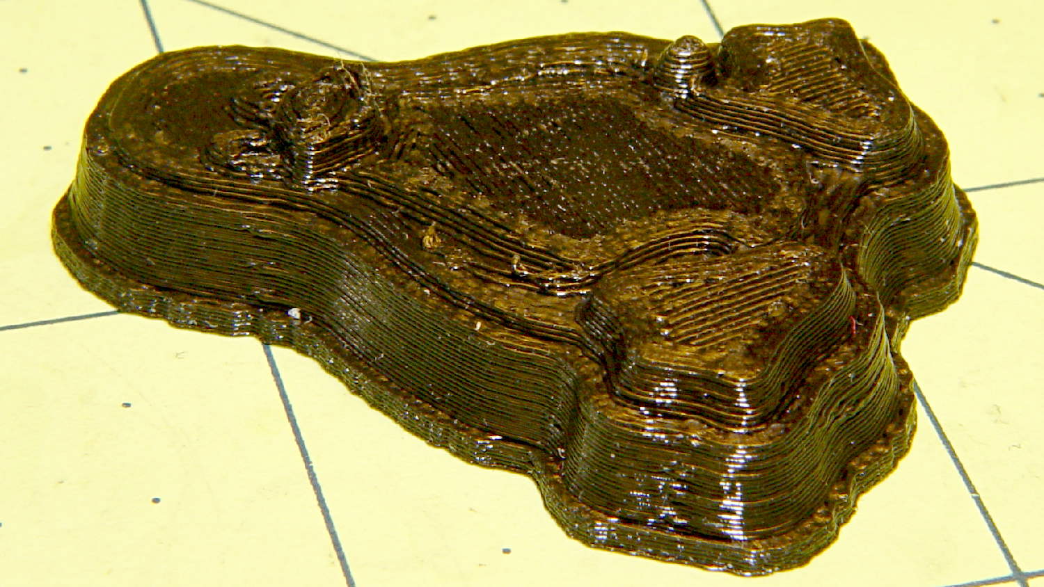
When it’s converted into plastic, you can count the layers in each V = 5 level (clicky for more dots):
Tux positive mold – plastic – oblique
It may be a bit less rounded in the tummy than the real Tux, but seems good enough for the purpose.