The Smell of Molten Projects in the Morning

Ed Nisley's Blog: Shop notes, electronics, firmware, machinery, 3D printing, laser cuttery, and curiosities. Contents: 100% human thinking, 0% AI slop.

Tag: CNC

Making parts with mathematics

  • Chocolate Mold Array: Solid Model Doodling

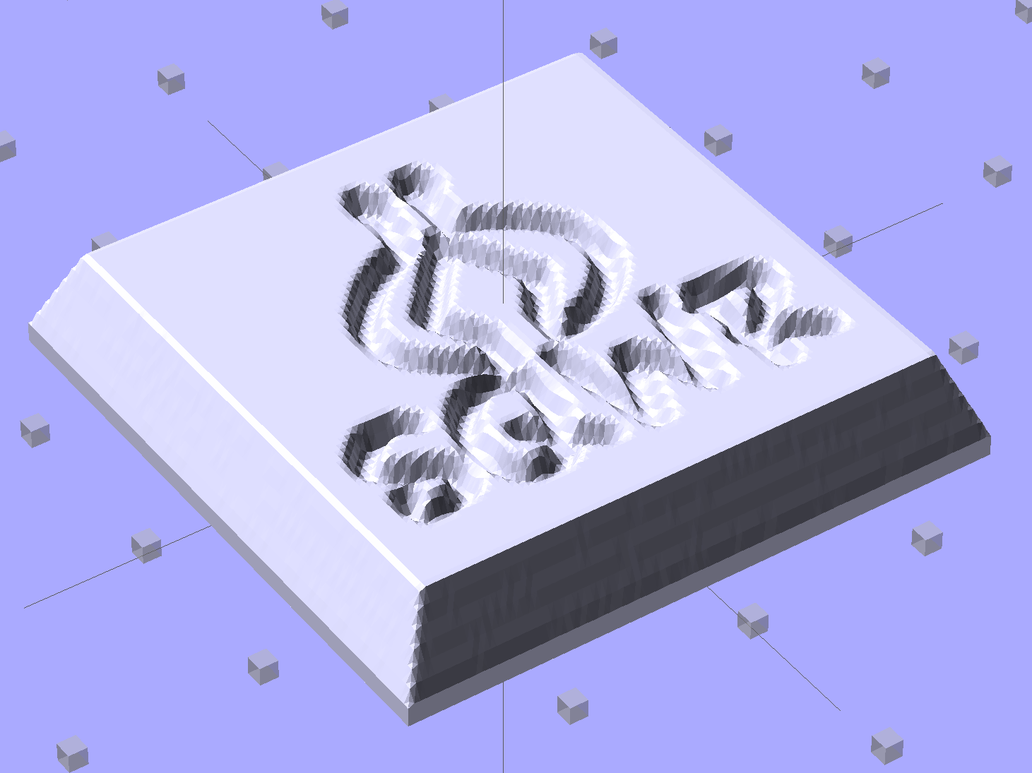
    Given an STL file generated from a height map image, import it into OpenSCAD:

    SqWr solid model - OpenSCAD - oblique view
    SqWr solid model – OpenSCAD – oblique view

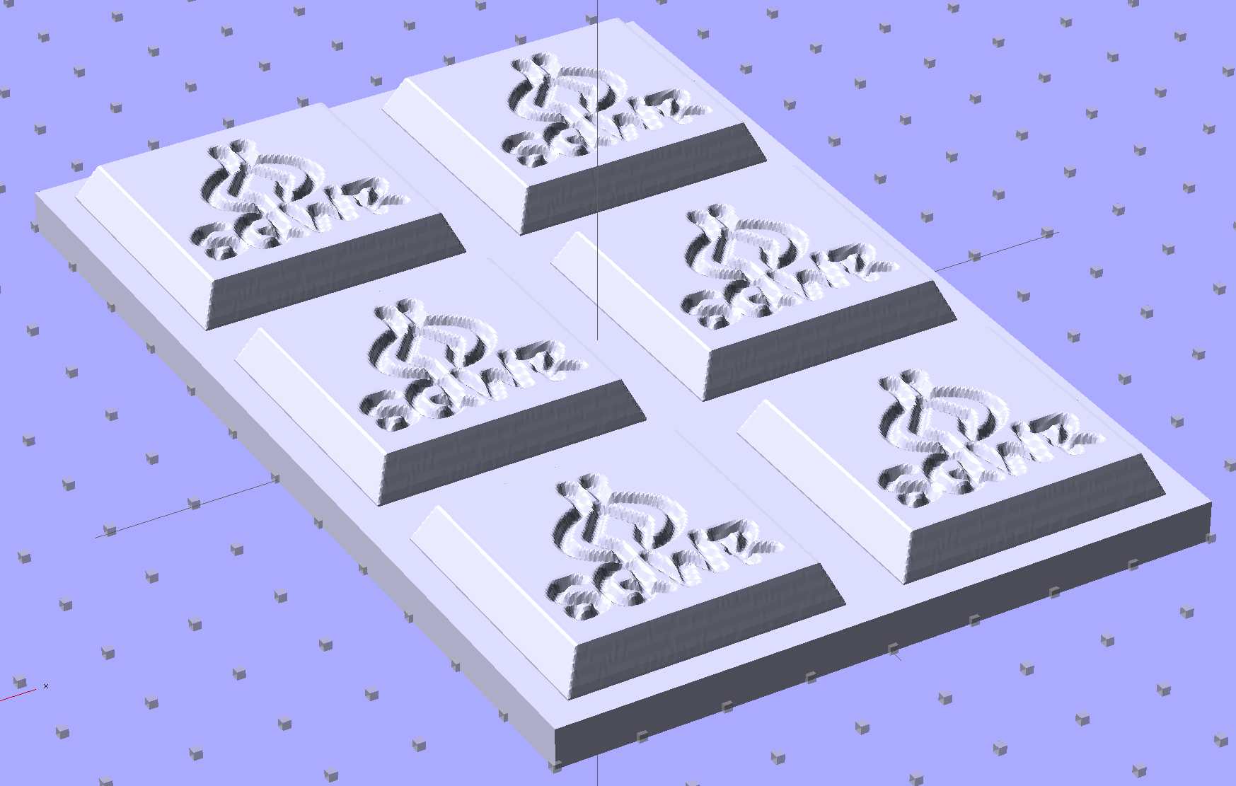
    Then slide a plate under six copies to produce a positive model for a casting mold:

    SqWr Positive Mold Framework - 2x3
    SqWr Positive Mold Framework – 2×3

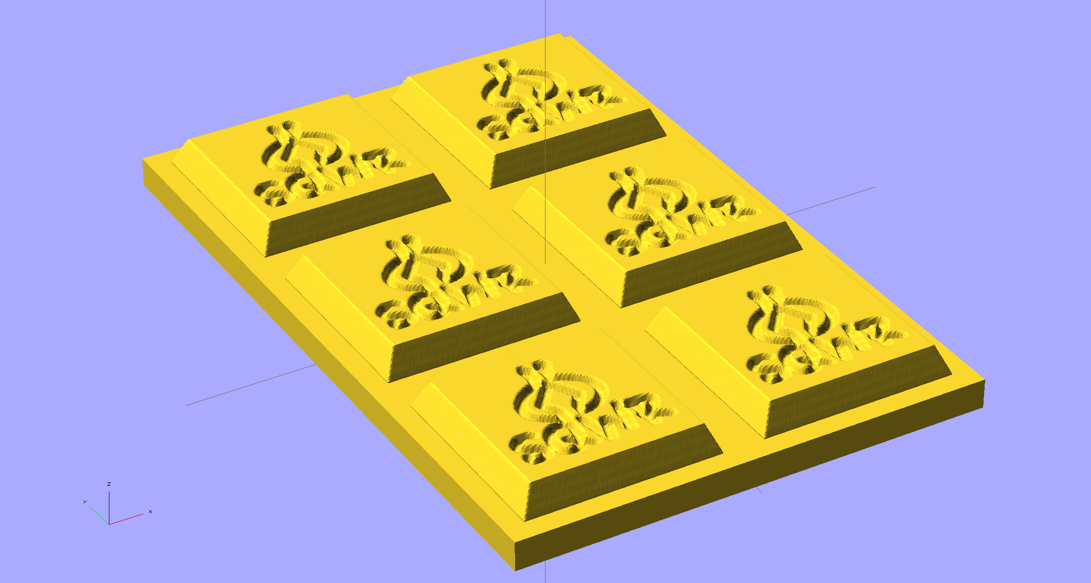
    This is one of the few cases where the compiled-and-rendered version looks better, as though you’d shrink-wrapped it in gold foil:

    SqWr Positive Mold Framework - 2x3 - gold
    SqWr Positive Mold Framework – 2×3 – gold

    The height map STLs each have  a bazillion tiny facets that take forever-and-a-day (well, the better part of half an hour for this set) to render, not to mention that the whole array would take two hours to print… and then be used once or twice to produce the flexy silicone negative mold.

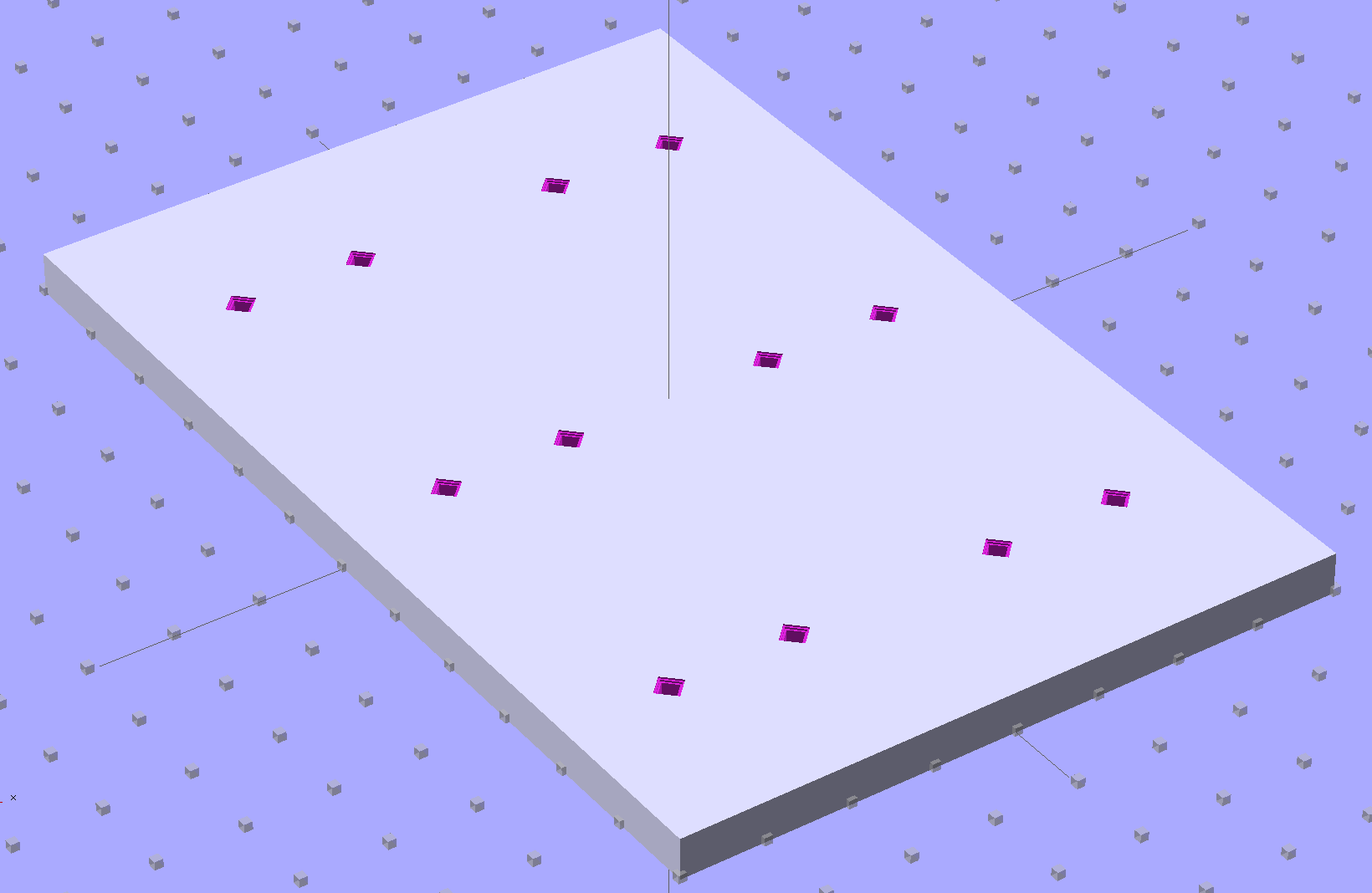
    So it’s better to have a generic frame with alignment pin holes that you print once:

    SqWr Positive Mold Framework - 2x3 pins
    SqWr Positive Mold Framework – 2×3 pins

    Better yet, just CNC-drill those holes in a nice, flat acrylic / polycarbonate slab.

    Insert and glue filament snippets as alignment pins, trim about 1 mm over the surface to fit the small molds.

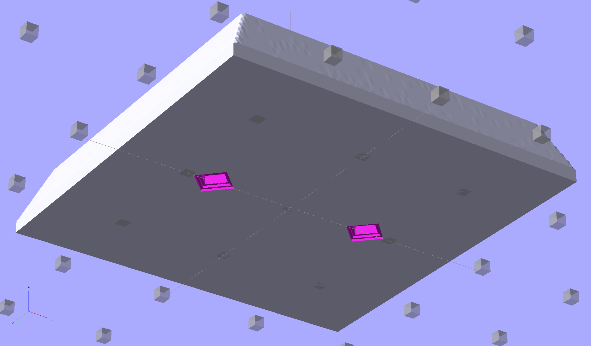
    The OpenSCAD program can punch matching holes in the back of the small mold:

    SqWr solid model - OpenSCAD - oblique bottom
    SqWr solid model – OpenSCAD – oblique bottom

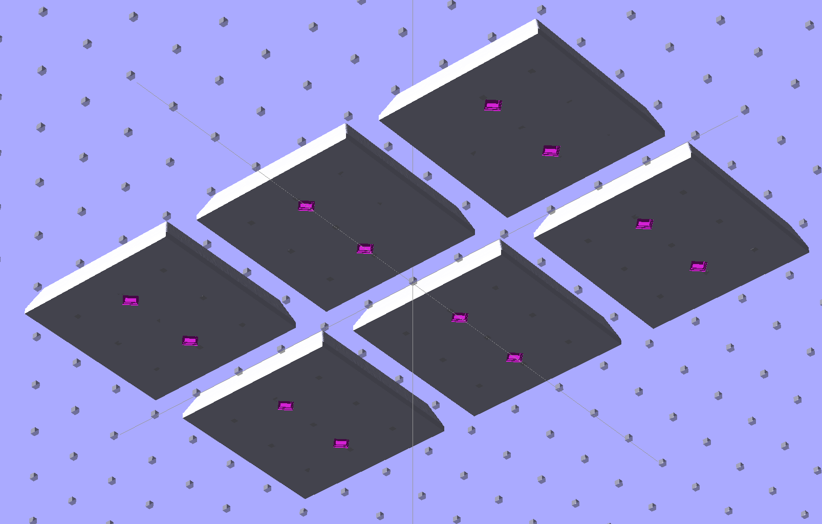
    Or you could print out an array of the things with holes:

    SqWr solid model - 2x3 array - bottom
    SqWr solid model – 2×3 array – bottom

    It’s not clear having OpenSCAD labor for half an hour to generate and emit a single STL file spanning all six molds is a win. Given that you don’t care about the mold-to-mold spacing, having Slic3r duplicate the same small STL file half a dozen (or more!) times would probably be a net win.

    There’s no reason the OpenSCAD program that creates the original STL from the height map image can’t punch alignment pin holes, too, which would avoid this import-and-recompile step. If you’re going with a CNC-drilled plate, then it would make even more sense to not have a pair of OpenSCAD programs.

    Anyhow.

    Apply a handful of small molds to the backing plate with tapeless sticky, butter it up with mold release agent, slather on silicone putty, flip it over to produce a smooth surface “under” the small molds (so you can rest it flat on a table when pouring molten chocolate into the cavities), cure, peel, and you’d get a pretty good negative mold.

    This may not make any practical sense, but it was easy & fun to see what’s possible…

    The OpenSCAD source code:

    // Positive mold framework for chocolate slabs
    // Ed Nisley - KE4ZNU - January 2014
    
    Layout = "FramePins";		// Molds FramePins FrameMolds Frame Single Pin
    
    //- Extrusion parameters must match reality!
    //  Print with 2 shells and 3 solid layers
    
    ThreadThick = 0.20;
    ThreadWidth = 0.40;
    
    Protrusion = 0.1;			// make holes end cleanly
    
    HoleWindage = 0.2;
    
    //----------------------
    // Dimensions
    
    FileName = "SqWr-press.stl";	// overrride with -D
    
    Molds = [2,3];					// count of molds within framework
    
    MoldOC = [40.0,40.0];			// on-center spacing of molds
    MoldSlab = 1.0;					// thickness of slab under molds
    
    BaseThick = 5.0;
    
    BaseSize = [(Molds[0]*MoldOC[0] + 0),(Molds[1]*MoldOC[1] + 0),BaseThick];
    echo(str("Overall base: ",BaseSize));
    
    PinOD = 1.75;					// locating pin diameter
    PinLength = 2.0;				//  ... total length
    PinSpace = 15.0;				// spacing within mold item
    
    //----------------------
    // Useful routines
    
    //- Put peg grid on build surface
    
    module ShowPegGrid(Space = 10.0,Size = 1.0) {
    
    	RangeX = floor(100 / Space);
    	RangeY = floor(125 / Space);
    
    	for (x=[-RangeX:RangeX])
    		for (y=[-RangeY:RangeY])
    			translate([x*Space,y*Space,Size/2])
    			%cube(Size,center=true);
    
    }
    
    module PolyCyl(Dia,Height,ForceSides=0) {			// based on nophead's polyholes
    
      Sides = (ForceSides != 0) ? ForceSides : (ceil(Dia) + 2);
    
      FixDia = Dia / cos(180/Sides);
    
      cylinder(r=(FixDia + HoleWindage)/2,
               h=Height,
    	   $fn=Sides);
    }
    
    // Locating pin hole with glue recess
    //  Default length is two pin diameters on each side of the split
    
    module LocatingPin(Dia=PinOD,Len=0.0) {
    
    	PinLen = (Len != 0.0) ? Len : (4*Dia);
    
    	translate([0,0,-ThreadThick])
    		PolyCyl((Dia + 2*ThreadWidth),2*ThreadThick,4);
    
    	translate([0,0,-2*ThreadThick])
    		PolyCyl((Dia + 1*ThreadWidth),4*ThreadThick,4);
    
    	translate([0,0,-(Len/2 + ThreadThick)])
    		PolyCyl(Dia,(Len + 2*ThreadThick),4);
    
    }
    
    module LocatingPins(Length) {
    	for (i=[-1,1])
    	translate([i*PinSpace/2,0,0])
    		LocatingPin(Len=Length);
    }
    
    //-- import a single mold item
    
    module MoldItem() {
    	import(FileName,convexity=10);
    }
    
    //-- Overall frame shape
    
    module Frame() {
    
    	translate([0,0,BaseSize[2]/2])		// platform under molds
    		cube(BaseSize,center=true);
    
    }
    
    //- Build it
    
    ShowPegGrid();
    
    if (Layout == "Pin")
    	LocatingPin(Len=PinLength);
    
    if (Layout == "Single")
    	difference() {
    		MoldItem();
    		LocatingPins(PinLength);
    	}
    
    if (Layout == "Frame")
    	Frame();
    
    if (Layout == "Molds") {
    	translate([-MoldOC[0]*(Molds[0] - 1)/2,-MoldOC[1]*(Molds[1] - 1)/2,0])
    	for (i=[0:Molds[0]-1],j=[0:Molds[1]-1])
    		translate([i*MoldOC[0],j*MoldOC[1],0])
    			difference() {
    				MoldItem();
    				LocatingPins(PinLength);
    			}
    }
    
    if (Layout == "FramePins")
    	difference() {
    		Frame();
    
    		translate([-MoldOC[0]*(Molds[0] - 1)/2,-MoldOC[1]*(Molds[1] - 1)/2,0])
    			for (i=[0:Molds[0]-1],j=[0:Molds[1]-1])
    				translate([i*MoldOC[0],j*MoldOC[1],BaseSize[2]])
    					LocatingPins(BaseThick);
    	}
    
    if (Layout == "FrameMolds") {
    	Frame();
    	translate([-MoldOC[0]*(Molds[0] - 1)/2,-MoldOC[1]*(Molds[1] - 1)/2,0])
    		for (i=[0:Molds[0]-1],j=[0:Molds[1]-1])
    			translate([i*MoldOC[0],j*MoldOC[1],BaseThick - MoldSlab + Protrusion])
    			MoldItem();
    }
    
  • Chocolate Mold Height Map

    Given that you really don’t care about the absolute dimensions, you can generate a positive mold from a height map image and avoid the entire solid modeling process. Having already solved the cookie press problem, this was a quick-and-easy feasibility study…

    Start by selecting the logo, growing the selection by a few pixels, and feathering the edges to produce the mold draft. Then apply a square gradient behind the Squidwrench logo to produce the height map for the edge of the mold. This one is scaled at 3.0 pixel/mm and is 100×100 pixel, thus producing a 33 mm square mold:

    Squidwrench Mold Pocket

    One could, of course, produce a non-square mold with a different gradient outline shape.

    Hand the image to a slightly modified version of the cookie press script (see below) to get an STL file of the mold:

    SqWr solid model - oblique view
    SqWr solid model – oblique view

    Feed the STL into Slic3r, hand the G-Code to Pronterface, fire the M2!, and you get a positive mold that looks enough like black chocolate to seem ready-to-eat:

    SqWr - mold positive
    SqWr – mold positive

    I have no idea whether that will work as a mold, but I suspect flexy silicone putty won’t reproduce much of the fine plastic filament detail, so the negative mold won’t grab the chocolate. The logo is six threads deep with a little bit of draft, if that makes any difference.

    The backing plate is 1 mm thick and the height map is 5 mm stacked atop that. A few iterations suggested using about 0.75 gray for the logo; working backwards says 5 mm = 25 layers @ 0.20 mm/layer, so a depth of 0.25 * 25 is about six threads.

    For production use, I’d be tempted to import maybe a dozen copies of the STL into OpenSCAD, mount them on a platform with a gutter and a lip on the outside, and then print the whole positive multi-cavity mold in one shot.

    The Bash script that produces the mold strongly resembles my cookie cutter script and contains about as much cruft as you’d expect. Because we need a positive mold, not a negative press, the script doesn’t invert the colors or flop the image left-to-right, nor does it generate the cookie cutter STL around the outside of the press:

    #!/bin/bash
    DotsPerMM=3.0
    MapHeight=7
    ImageName="${1%%.*}"
    rm ${ImageName}_* ${ImageName}-press.stl ${ImageName}-cutter.stl
    echo Normalize and prepare grayscale image...
    convert $1 -type Grayscale -depth 8 -auto-level -trim +repage -flip +set comment ${ImageName}_prep.png
    echo Create PGM files...
    convert ${ImageName}_prep.png -compress none ${ImageName}_map.pgm
    convert ${ImageName}_prep.png -white-threshold 1 -compress none ${ImageName}_plate.pgm
    echo Create height map data files...
    ImageX=`identify -format '%[fx:w]' ${ImageName}_map.pgm`
    ImageY=`identify -format '%[fx:h]' ${ImageName}_map.pgm`
    echo Width: ${ImageX} x Height: ${ImageY}
    cat ${ImageName}_map.pgm   | tr -s ' \012' '\012' | tail -n +5 | column -x -c $((8*$ImageX)) > ${ImageName}_map.dat
    cat ${ImageName}_plate.pgm | tr -s ' \012' '\012' | tail -n +5 | column -x -c $((8*$ImageX)) > ${ImageName}_plate.dat
    echo Create cookie press...
    time openscad -D BuildPress=true \
    -D fnPlate=\"${ImageName}_plate.dat\" \
    -D fnMap=\"${ImageName}_map.dat\" -D Height=$MapHeight \
    -D ImageX=$ImageX -D ImageY=$ImageY -D DotsPerMM=$DotsPerMM \
    -o ${ImageName}-press.stl Cookie\ Cutter.scad
    

    The OpenSCAD program are unchanged from the cookie cutter process.

  • Sony NP-BX1 Battery Test Fixture

    The Sony HDR-AS30V “action camera” uses NP-BX1 lithium batteries (3.7 V @ 1.24 A·h = 4.6 W·h) that are, of course, a completely different size and shape than any other lithium battery on the planet.

    So.

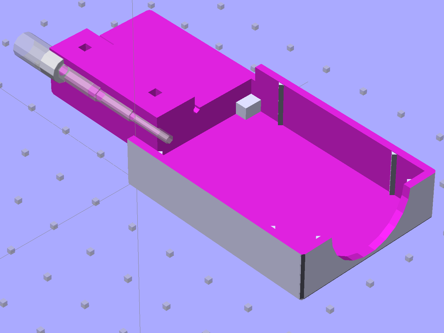
    Tweaking a few dimensions in the Canon NB-6L source code, tinkering with the layout of the contact pins, and shazam Yet Another 3D Printed Battery Test Fixture:

    NP-BX1 Holder - show layout
    NP-BX1 Holder – show layout

    It builds nicely, although the contact pin tunnels are a bit too close to the top of the case:

    Sony NP-BX1 Holder - on platform
    Sony NP-BX1 Holder – on platform

    After reaming out the contact pin holes to the proper diameters & depths, then gluing the plugs in place, it works just as you’d expect:

    Sony NP-BX1 battery holder
    Sony NP-BX1 battery holder

    It’s worth noting that the Wasabi charger accepts the batteries upside-down, with the conspicuous chevron against the charger body. It’s definitely not the way all the other chargers work. The keying recesses on the battery (corresponding to the blocks in the solid model) lie along the bottom edge of the contact surface, so flipping the battery over means they’ll hold it in place, but … oh, well.

    That grotty Powerpole connector last saw use in some random benchtop lashup. At some point I’ll be forced to start making more of those.

    The OpenSCAD source code:

    // Holder for Sony NP-BX1 Li-Ion battery
    // Ed Nisley KE4ZNU January 2013
    
    include <MCAD/boxes.scad>
    
    // Layout options
    
    Layout = "Show";					//  Show Build Fit Case Lid Pins Plugs AlignPins
    
    //- Extrusion parameters - must match reality!
    //  Print with +2 shells and 3 solid layers
    
    ThreadThick = 0.20;
    ThreadWidth = 0.40;
    
    HoleWindage = 0.2;
    
    function IntegerMultiple(Size,Unit) = Unit * ceil(Size / Unit);
    
    Protrusion = 0.1;			// make holes end cleanly
    
    inch = 25.4;
    
    BuildOffset = 3.0;			// clearance for build layout
    
    Gap = 8.0;					// separation for Fit parts
    
    //- Battery dimensions - rationalized from several samples
    //  Coordinate origin at battery corner by contact plates on bottom surface
    
    BatteryLength = 43.0;
    BatteryWidth = 30.0;
    BatteryThick =  9.5;
    
    ContactWidth = 2.90;
    ContactLength = 4.30;
    ContactRecess = 0.90;
    
    ContactOC = 10.0;			// center-to-center across contact face
    ContactOffset = 6.20;		// offset from battery edge
    ContactHeight = 6.30;		// offset from battery bottom plane
    
    AlignThick = 2.75;			// alignment recesses on contact face
    AlignDepth = 1.70;			// into face
    AlignWidth1 = 3.70;			// across face at contacts
    AlignWidth2 = 3.60;			//  ... other edge
    
    //- Pin dimensions
    
    PinTipDia = 1.6;
    PinTipLength = 10.0;
    
    PinTaperLength = 2.3;
    
    PinShaftDia = 2.4;
    PinShaftLength = 6.8;
    
    PinFerruleDia = 3.1;
    PinFerruleLength = 2.0;
    
    PinLength = PinTipLength + PinTaperLength + PinShaftLength + PinFerruleLength;
    
    ExtendRelax = 1.5 + ContactRecess;		// pin extension when no battery is present
    ExtendOvertravel = 1.0;					//  ... beyond engaged position
    
    //- Spring dimensions
    
    SpringDia = 3.1;						// coil OD
    SpringMax = 9.3;
    SpringLength = SpringMax - 0.5;			// slightly compressed
    SpringMin = 4.5;
    
    SpringPlugOD = IntegerMultiple(5.0,ThreadWidth);		// plug retaining the spring
    SpringPlugID = 2.0;
    SpringPlugLength = IntegerMultiple(4.0,ThreadWidth);
    SpringPlugSides = 3*4;
    
    SpringTravel = ExtendRelax + ExtendOvertravel;
    
    //- Holder dimensions
    
    GuideRadius = ThreadWidth;			// friction fit ridges
    GuideOffset = 7;					// from compartment corners
    WallThick = 4*ThreadWidth;			// holder sidewalls
    
    BaseThick = 6*ThreadThick;			// bottom of holder to bottom of battery
    TopThick = 6*ThreadThick;			// top of battery to top of holder
    
    ThumbRadius = 10.0;			// thumb opening at end of battery
    
    CornerRadius = 3*ThreadThick;			// nice corner rounding
    
    CaseLength = SpringPlugLength + SpringLength + PinLength - ExtendRelax
    			+ BatteryLength + GuideRadius + WallThick;
    CaseWidth = 2*WallThick + 2*GuideRadius + BatteryWidth;
    CaseThick = BaseThick + BatteryThick + TopThick;
    
    AlignPinOD = 1.75;			// lid alignment pins - filament snippets
    AlignPinLength = 5.0;
    AlignPinInset = 7.0;
    AlignPinOffset = -3.75;		//  from centerline - choose to miss contact pins
    
    //- XY origin at front left battery corner, Z on platform below that
    
    CaseLengthOffset = -(SpringPlugLength + SpringLength + PinLength - ExtendRelax);
    CaseWidthOffset = -(WallThick + GuideRadius);
    CaseThickOffset = BaseThick;
    
    LidLength = ExtendRelax - CaseLengthOffset;
    
    echo(str("Contact pin tip dia: ",PinTipDia));
    echo(str("Drill depth to taper end: ",
    		 (SpringPlugLength + SpringLength + PinFerruleLength + PinShaftLength + PinTaperLength),
    		 " -- Dia: ",PinShaftDia));
    echo(str("            to ferrule end: ",
    		  (SpringPlugLength + SpringLength + PinFerruleLength),
    		 " -- Dia: ",PinFerruleDia));
    echo(str("            to plug end: ",SpringPlugLength,
    		 " -- Dia: ",SpringPlugOD));
    
    //----------------------
    // Useful routines
    
    module PolyCyl(Dia,Height,ForceSides=0) {			// based on nophead's polyholes
    
      Sides = (ForceSides != 0) ? ForceSides : (ceil(Dia) + 2);
    
      FixDia = Dia / cos(180/Sides);
    
      cylinder(r=(FixDia + HoleWindage)/2,
               h=Height,
    	   $fn=Sides);
    }
    
    module ShowPegGrid(Space = 10.0,Size = 1.0) {
    
      Range = floor(50 / Space);
    
    	for (x=[-Range:Range])
    	  for (y=[-Range:Range])
    		translate([x*Space,y*Space,Size/2])
    		  %cube(Size,center=true);
    
    }
    
    //-------------------
    
    //-- Guides for tighter friction fit
    
    module Guides() {
      	  translate([GuideOffset,-GuideRadius,CaseThickOffset])
    		PolyCyl(2*GuideRadius,(BatteryThick - Protrusion),4);
    	  translate([GuideOffset,(BatteryWidth + GuideRadius),CaseThickOffset])
    		PolyCyl(2*GuideRadius,(BatteryThick - Protrusion),4);
    	  translate([(BatteryLength - GuideOffset),-GuideRadius,CaseThickOffset])
    		PolyCyl(2*GuideRadius,(BatteryThick - Protrusion),4);
    	  translate([(BatteryLength - GuideOffset),(BatteryWidth + GuideRadius),CaseThickOffset])
    		PolyCyl(2*GuideRadius,(BatteryThick - Protrusion),4);
    	  translate([(BatteryLength + GuideRadius),GuideOffset/2,CaseThickOffset])
    		PolyCyl(2*GuideRadius,(BatteryThick - Protrusion),4);
    	  translate([(BatteryLength + GuideRadius),(BatteryWidth - GuideOffset/2),CaseThickOffset])
    		PolyCyl(2*GuideRadius,(BatteryThick - Protrusion),4);
    
    }
    
    //-- Contact pins (holes therefore)
    
    module PinShape() {
    
      union() {
    	cylinder(r=(PinTipDia + HoleWindage)/2,h=(PinTipLength + Protrusion),$fn=6);
    
    	translate([0,0,PinTipLength])
    	  cylinder(r=(PinShaftDia + HoleWindage)/2,
    			   h=(PinTaperLength + PinShaftLength + Protrusion),$fn=6);
    
    	translate([0,0,(PinLength - PinFerruleLength)])
    	  cylinder(r=(PinFerruleDia + HoleWindage)/2,
    				h=(PinFerruleLength + Protrusion),$fn=6);
    
    	translate([0,0,(PinLength)])
    	  cylinder(r=(SpringDia + HoleWindage)/2,
    				h=(SpringLength + Protrusion),$fn=6);
    
    	translate([0,0,(PinLength + SpringLength - HoleWindage)])	// windage for hole length
    	  cylinder(r=(SpringPlugOD + HoleWindage)/2,h=3*SpringPlugLength,$fn=SpringPlugSides);
    
    //	  translate([0,0,(PinLength + SpringLength + SpringPlugLength)])
    //	  cylinder(r=(SpringPlugOD + HoleWindage)/2,h=2*SpringPlugLength,$fn=SpringPlugSides);	// extend hole
      }
    
    }
    
    module PinAssembly() {
    
      translate([ExtendRelax,ContactOffset,CaseThickOffset + ContactHeight]) {
    	rotate([0,270,0]) {
    	  PinShape();												// pins
    	  translate([0,(1*ContactOC),0])
    		PinShape();
    	}
      }
    
    }
    
    //-- Alignment pins
    
    module AlignPins() {
    
    	for (x=[-1,1])
    		translate([x*(LidLength - 2*AlignPinInset)/2,AlignPinOffset,0])
    			rotate(45)
    			PolyCyl(AlignPinOD,AlignPinLength);
    }
    
    //-- Case with origin at battery corner
    
    module Case() {
    
      difference() {
    
    	union() {
    
    	  difference() {
    		translate([(CaseLength/2 + CaseLengthOffset),
    				  (CaseWidth/2 + CaseWidthOffset),
    				  (CaseThick/2)])
    		  roundedBox([CaseLength,CaseWidth,CaseThick],CornerRadius); 	// basic case shape
    
    		translate([-ExtendOvertravel,-GuideRadius,CaseThickOffset])
    		  cube([(BatteryLength + GuideRadius + ExtendOvertravel),
    				(BatteryWidth + 2* GuideRadius),
    				(BatteryThick + Protrusion)]);						// battery space
    
    	  }
    
    	  Guides();
    
    	  translate([-ExtendOvertravel,-GuideRadius,BaseThick])
    		cube([(AlignDepth + ExtendOvertravel),
    			  (AlignWidth1 + GuideRadius),
    			  AlignThick]);											// alignment blocks
    	  translate([-ExtendOvertravel,
    				 (BatteryWidth - AlignWidth2),
    				 BaseThick])
    		cube([(AlignDepth + ExtendOvertravel),
    			  (AlignWidth2 + GuideRadius),
    			  AlignThick]);
    
    	}
    
    	translate([(-ExtendOvertravel),
    			   (CaseWidthOffset - Protrusion),
    			   (CaseThickOffset + BatteryThick)])
    	  cube([CaseLength,
    		    (CaseWidth + 2*Protrusion),
    		    (TopThick + Protrusion)]);								// battery access
    
    	translate([(CaseLengthOffset - Protrusion),
    			   (CaseWidthOffset - Protrusion),
    			   (CaseThickOffset + BatteryThick)])
    	  cube([(CaseLength + 2*Protrusion),
    		    (CaseWidth + 2*Protrusion),
    		    (TopThick + Protrusion)]);								// battery insertion allowance
    
    	translate([(BatteryLength - Protrusion),
    			    (CaseWidth/2 + CaseWidthOffset),
    			    (CaseThickOffset + ThumbRadius)])
    	  rotate([90,0,0])
    		rotate([0,90,0])
    		  cylinder(r=ThumbRadius,
    				   h=(WallThick + GuideRadius + 2*Protrusion),
    				   $fn=22);											// remove thumb notch
    
    	PinAssembly();
    
    	translate([-LidLength/2,BatteryWidth/2,CaseThick - TopThick - (AlignPinLength - TopThick/2)])
    		AlignPins();
      }
    
    }
    
    module Lid() {
    
      difference() {
    	translate([0,0,(CaseThick/2 - BaseThick - BatteryThick)])
    	  roundedBox([LidLength,
    				 CaseWidth,CaseThick],CornerRadius);
    
    	translate([0,0,-(CaseThick/2)])
    	  cube([(LidLength + 2*Protrusion),
    		    (CaseWidth + 2*Protrusion),
    		    (CaseThick)],center=true);
    
    	translate([-ExtendRelax,0,-(AlignPinLength - TopThick/2)])
    		AlignPins();
      }
    
    }
    
    module PlugShape() {
    
      difference() {
    	cylinder(r=SpringPlugOD/2,h=SpringPlugLength,$fn=SpringPlugSides);
    	translate([0,0,-Protrusion])
    	  PolyCyl(SpringPlugID,(SpringPlugLength + 2*Protrusion),SpringPlugSides);
      }
    }
    
    module Plugs() {
      translate([0,ContactOC,0])
    	PlugShape();
      translate([0,-ContactOC,0])
    	PlugShape();
    }
    
    //-------------------
    // Build it!
    
    ShowPegGrid();
    
    if (Layout == "Case")
      Case();
    
    if (Layout == "Lid")
      Lid();
    
    if (Layout == "Plugs")
    	for (i=[-1:1])
    		translate([i*1.5*SpringPlugOD,0,0])
    			Plugs();
    
    if (Layout == "Pins")
      PinShape();
    
    if (Layout == "AlignPins")
      AlignPins();
    
    if (Layout == "Show") {								// reveal pin assembly
      difference() {
    	Case();
    
    	translate([(CaseLengthOffset - Protrusion),
    			   (CaseWidthOffset - Protrusion + WallThick + ContactOffset + ContactOC),
    			   (BaseThick + ContactHeight)])
    	  cube([(-CaseLengthOffset + Protrusion),
    			 (CaseWidth + 2*Protrusion),
    			 CaseThick + BaseThick - ContactHeight + Protrusion]);
    
    	translate([(CaseLengthOffset - Protrusion),
    			   (CaseWidthOffset - Protrusion),
    			   -Protrusion])
    	  cube([(-CaseLengthOffset + Protrusion),
    			 (WallThick + GuideRadius + ContactOffset + Protrusion),
    			 CaseThick]);
      }
    
      translate([ExtendRelax,ContactOffset,(CaseThickOffset + ContactHeight)]) {	// pins
    	rotate([0,270,0]) {
    	  %PinShape();
    //	  translate([0,(2*ContactOC),0])
    //		%PinShape();
    	}
      }
    
      translate([CaseLengthOffset,ContactOffset,(CaseThickOffset + ContactHeight)])
    	rotate([0,90,0])
    	  PlugShape();
    }
    
    if (Layout == "Build") {
      translate([-(CaseLength/2 + CaseLengthOffset),-(CaseWidthOffset - BuildOffset),0])
    	Case();
      translate([CaseWidth/2,(CaseLengthOffset/2 - BuildOffset),0])
    	rotate([0,0,90])
    	  Lid();
      for (i=[-1:1])
    	translate([CaseLengthOffset/2 + i*1.5*SpringPlugOD,-CaseWidth/2,0])
    		Plugs();
    }
    
    if (Layout == "Fit") {
      Case();
      translate([(-LidLength/2 + ExtendRelax),
    			(CaseWidth/2 + CaseWidthOffset),
    			(BaseThick + BatteryThick + Gap)])
    	  Lid();
      translate([ExtendRelax,ContactOffset,CaseThickOffset + ContactHeight]) {	// pins
    	rotate([0,270,0]) {
    	  %PinShape();
    	  translate([0,(1*ContactOC),0])
    		%PinShape();
    	}
      }
    
      translate([CaseLengthOffset,
    			(ContactOffset + ContactOC),
    			(CaseThickOffset + ContactHeight)])
      rotate([0,90,0])
    	Plugs();
    
      translate([-LidLength/2,BatteryWidth/2,CaseThick])
    #	AlignPins();
    
    }
    
  • Rounded Rectangles in OpenSCAD: Mold Positives?

    A discussion on the OpenSCAD mailing list about making a rectangular solid with rounded edges having different radii eventually produced this delightful result:

    Basic Rounded Cube
    Basic Rounded Cube

    Those guys make me feel dumb, because they’re generally solving problems I can’t even imagine, but I know what to do with this solution. One could slice it in half horizontally, emboss a height map defining a logo / picture into the top surface, print it out on your favorite 3D printer, maybe smooth / seal the surface a bit, define it to be a positive mold pattern, cast / pour flexible silicone around it, and get a negative mold for a pourable precious material such as, oh, chocolate.

    You could make half a dozen of them, arrange them inside a suitable printed frame, pour the silicone, and get a multi-cavity mold for better manufacturing productivity.

    The overall block lacks draft, because the problem it solves presumes you need a block of specific outside dimensions: it overlays three full-size rectangular blocks that define the dimensions. OpenSCAD constructs spheres such that they may be slightly smaller than the defined radius at the poles and, depending on their alignment, a face at the equator may reduce the outer dimension of a surrounding hull.

    Given a sufficiently bendy silicone mold, you might not need any draft at all. If you do need draft and you don’t care about a very slightly undersized pattern, remove the internal blocks and increase the XY spacing of the lower four spheres by enough to make the draft come out right.

    The grayscale logo / image should have nice smooth transitions that produce suitable draft for the fine details; a bare black-and-white image might not work well. Shallow is good, but that conflicts with 3D printing’s crappy resolution: 1 mm = 10 layers, tops. That might not matter in practice.

    You’re supposed to temper the chocolate, but that’s probably more relevant for Fine Art molds.

    The (slightly modified) OpenSCAD source code:

    module rcube(size=[30, 20, 10], radius=[3, 2, 1], center=true)
    	hull() {
    		translate( center ? [0,0,0] : size/2 ) {
    			cube(size-2*radius+[2*radius[0],0,0],center=true);
    			cube(size-2*radius+[0,2*radius[1],0],center=true);
    			cube(size-2*radius+[0,0,2*radius[2]],center=true);
    
    			for(x = [-0.5,0.5], y = [-0.5,0.5], z = [-0.5,0.5])
    				translate([x * ( size[0] - 2*radius[0]),
    						   y * ( size[1] - 2*radius[1]),
    						   z * ( size[2] - 2*radius[2])])
    					scale([radius[0], radius[1], radius[2]])
    						sphere(1.0,$fn=4*4);
    		}
    	}
    
    rcube();
    

    When I get around to doing molds, maybe I can remember what I was thinking…

  • Thing-O-Matic 286 Conversion: Slic3r Configuration

    The Thing-O-Matic hardware isn’t up to the standards of, say, an M2, but, after all my tweakage, it’s Good Enough for most purposes. These Slic3r settings should provide a reasonable starting point to get it working the way it used to with its new controller.

    The key extrusion dimensions:

    • 0.4 mm nozzle → 0.5 mm minimum thread width
    • 0.25 mm layer thickness

    The speeds come from the old Skeinforge configuration, dialed back a bit for sanity:

    • 150 mm/s non-printing XY travel
    • 10 mm/s minimum printing speed
    • 20 mm/s first layer printing for better adhesion
    • 40 mm/s general printing
    • 60 mm/s infill

    Some of the finer settings are completely arbitrary and everything requires tweaking, along with Marlin’s acceleration & jerk settings, for best picture.

    The exported Slic3r configuration:

    # generated by Slic3r 1.0.0RC1 on Fri Jan 17 11:25:02 2014
    avoid_crossing_perimeters = 0
    bed_size = 105,120
    bed_temperature = 110
    bottom_solid_layers = 3
    bridge_acceleration = 0
    bridge_fan_speed = 100
    bridge_flow_ratio = 1
    bridge_speed = 40
    brim_width = 0
    complete_objects = 0
    cooling = 1
    default_acceleration = 0
    disable_fan_first_layers = 1000
    duplicate = 1
    duplicate_distance = 6
    duplicate_grid = 1,1
    end_gcode = ;---- end.gcode starts ----\n; TOM 286 - Al plates + Geared extruder\n; Ed Nisley - KE4ZNU - January 2014\n; Marlin with tweaks for Azteeg X3 with thermocouple\n;- inhale filament blob\nG91\nG1 E-5 F900\nG90\n;- turn off heaters\nM104 S0         ; extruder head\nM140 S0         ; HBP\n;- move to eject position\nG1 Z999 F1000   ; home Z to get nozzle away from object\nG92 Z115      ; reset Z\nG1 X0 F6000     ; center X axis\nG1 Y35          ; move Y stage forward\n;---- end.gcode ends ----
    external_perimeter_speed = 50%
    external_perimeters_first = 0
    extra_perimeters = 1
    extruder_clearance_height = 20
    extruder_clearance_radius = 20
    extruder_offset = 0x0
    extrusion_axis = E
    extrusion_multiplier = 1.00
    extrusion_width = 0.50
    fan_always_on = 0
    fan_below_layer_time = 1
    filament_diameter = 2.95
    fill_angle = 45
    fill_density = 0.15
    fill_pattern = honeycomb
    first_layer_acceleration = 0
    first_layer_bed_temperature = 110
    first_layer_extrusion_width = 0.50
    first_layer_height = 0.25
    first_layer_speed = 20
    first_layer_temperature = 200
    g0 = 0
    gap_fill_speed = 30
    gcode_arcs = 0
    gcode_comments = 0
    gcode_flavor = reprap
    infill_acceleration = 0
    infill_every_layers = 3
    infill_extruder = 1
    infill_extrusion_width = 0.50
    infill_first = 1
    infill_only_where_needed = 1
    infill_speed = 60
    layer_gcode =
    layer_height = 0.25
    max_fan_speed = 100
    min_fan_speed = 35
    min_print_speed = 10
    min_skirt_length = 5
    notes =
    nozzle_diameter = 0.4
    only_retract_when_crossing_perimeters = 1
    ooze_prevention = 0
    output_filename_format = [input_filename_base].gcode
    overhangs = 1
    perimeter_acceleration = 0
    perimeter_extruder = 1
    perimeter_extrusion_width = 0.50
    perimeter_speed = 40
    perimeters = 2
    post_process =
    print_center = 0,0
    raft_layers = 0
    randomize_start = 1
    resolution = 0.05
    retract_before_travel = 0.5
    retract_layer_change = 0
    retract_length = 2
    retract_length_toolchange = 10
    retract_lift = 0
    retract_restart_extra = 0
    retract_restart_extra_toolchange = 0
    retract_speed = 60
    rotate = 0
    scale = 1
    skirt_distance = 2
    skirt_height = 1
    skirts = 3
    slowdown_below_layer_time = 15
    small_perimeter_speed = 50%
    solid_fill_pattern = rectilinear
    solid_infill_below_area = 5
    solid_infill_every_layers = 0
    solid_infill_extrusion_width = 0.50
    solid_infill_speed = 150%
    spiral_vase = 0
    standby_temperature_delta = -5
    start_gcode = ;---- start.gcode begins ----\n; TOM 286 - Al plates + Geared extruder + Zmin platform sense\n; Ed Nisley - KE4ZNU - January 2014\n; Marlin with tweaks for Azteeg X3 with thermocouple\n;\n; Set initial conditions\nG21                 ; set units to mm\nG90                 ; set positioning to absolute\n;----------\n; Begin heating\nM104 S[first_layer_temperature]         ; extruder head\nM140 S[first_layer_bed_temperature]    ; start bed heating\n;----------\n; Home axes\nG28 X0 Y0 Z0\nG92 X-53.5 Y-58.5 Z115.0\n;----------\n; Initial nozzle wipe to clear snot for Z touchoff\nG1 X0 Y0 Z3.0 F1500     ; pause at center to build confidence\nG4 P1000\nG1 Z10                  ; ensure clearance\nG1 X39 Y-58.0 F10000    ; move to front, avoid wiper blade\nG1 X55                  ; to wipe station\nG1 Z6.0                 ; to wipe level\nM116                    ; wait for temperature settling\nG1 Y-45 F500            ; slowly wipe nozzle\n;-----------------------------------------------\n; Z platform height touchoff\n; Make sure the XY position is actually over the switch!\n; Home Z downward to platform switch\n; Compensate for 0.05 mm backlash in G92: make it 0.05 too low\nG1 X56.0 Y8.2 Z4.0 F6000     ; get over build platform switch\n;G1 Z0 F50                    ; home downward very slowly\n;G92 Z1.45                    ; set Z-min switch height\nG1 Z6.0 F1000                ; back off switch to wipe level\n;-----------------------------------------------\n; Prime extruder to stabilize initial pressure\nG1 X55 Y-45 F6000   ; set up for wipe from rear\nG1 Y-58.0 F500      ; wipe to front\nG91                 ; use incremental motion for extrusion\nG1 F2               ; set slow rate\nG1 E10              ; extrude enough to get good pressure\nG1 F4000            ; set for fast retract\nG1 E-2.0            ; retract\nG90                 ; back to absolute motion\nG1 Y-45 F1000       ; wipe nozzle to rear\n;----------\n; Set up for Skirt start in left rear corner\n; Compensate for Z backlash: move upward from zero point\nG1 X-50 Y55 Z0.0 F10000     ; left rear corner -- kiss platform\nG1 Z0.2 F1500       ; take up Z backlash to less than thread height\nG92 E1.0            ; preset to avoid huge un-Reversal blob\n;G1 X0 Y0\n;---- start.gcode ends ----
    start_perimeters_at_concave_points = 1
    start_perimeters_at_non_overhang = 1
    support_material = 0
    support_material_angle = 0
    support_material_enforce_layers = 0
    support_material_extruder = 1
    support_material_extrusion_width = 0.50
    support_material_interface_extruder = 1
    support_material_interface_layers = 3
    support_material_interface_spacing = 0
    support_material_pattern = honeycomb
    support_material_spacing = 2.5
    support_material_speed = 60
    support_material_threshold = 0
    temperature = 200
    thin_walls = 1
    threads = 2
    toolchange_gcode =
    top_infill_extrusion_width = 0.50
    top_solid_infill_speed = 50%
    top_solid_layers = 3
    travel_speed = 150
    use_firmware_retraction = 0
    use_relative_e_distances = 0
    vibration_limit = 0
    wipe = 0
    z_offset = 0
    
  • Canon NB-6LH Battery Test Fixture

    Our Larval Engineer’s new camera uses Canon NB-6LH batteries, which have exactly the same nominal capacity as the NB-5L batteries for my camera, despite being not quite the same size. I cannot imagine any reason for that, other than brand fractionation, but there it is.

    Fortunately, the sizes are pretty close, so I conjured up another 3D printed battery test fixture for the rundown tests:

    Canon NB-6L battery holder
    Canon NB-6L battery holder

    That hideous Powerpole thing came from one of the AA cell packs I’d been using to power the HTs on the bikes, before switching to lithium battery packs. It’s easier to harvest something suitable than to build a new thing, particularly for such a low duty cycle gadget.

    This view of the solid model shows the contact pins, with the lid floating over its alignment pegs (made from snippets of 1.75 mm filament):

    NB-6L Holder - fit layout
    NB-6L Holder – fit layout

    The pegs simplify gluing the lid in place, a process for which you can never have enough clamps:

    Canon NB-6L holder - lid gluing
    Canon NB-6L holder – lid gluing

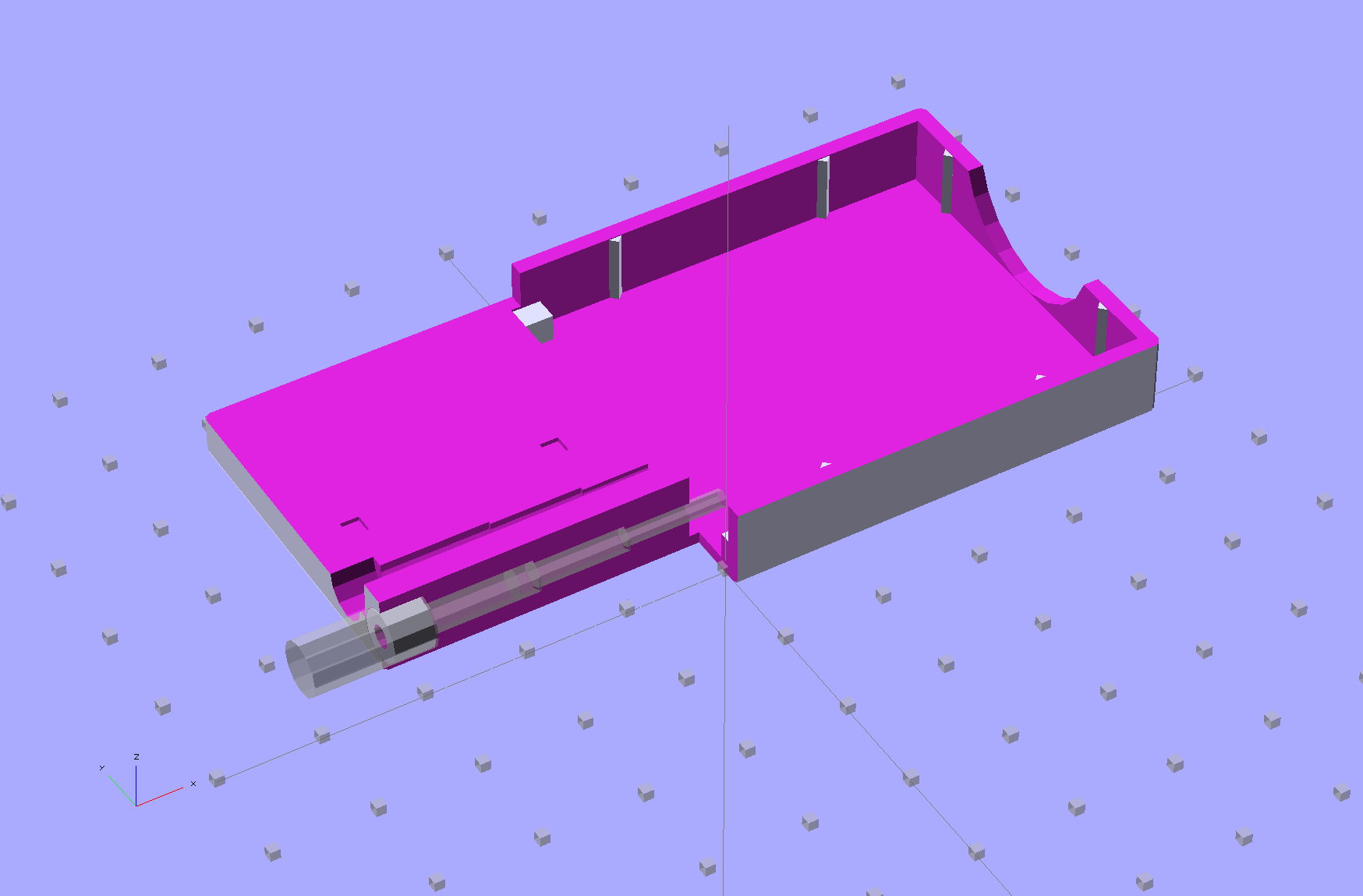
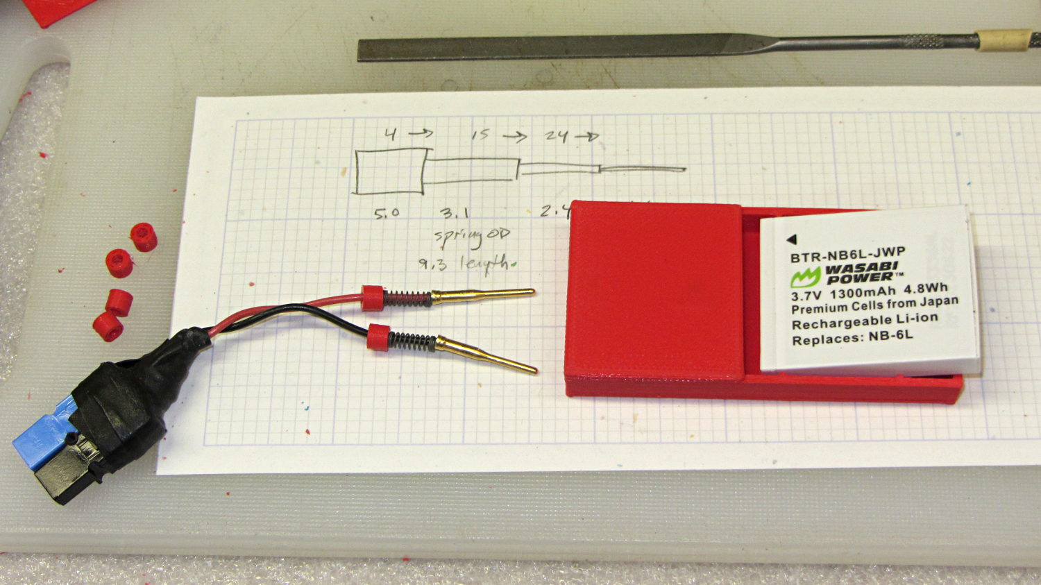
    A cutaway shows the stepped holes around the contact pin, with the coil springs being the largest cylinder to the right of the solid-looking plug:

    NB-6L Holder - show layout
    NB-6L Holder – show layout

    The contact pins look like this, at least after one remembers to slide on all the parts before soldering the wires in place:

    Canon NB-6L holder - contact pin detail
    Canon NB-6L holder – contact pin detail

    I filed off the inevitable solder bumps, rounded the butt ends with gentle suasion, and generally tidied the pins up so they’re smooth and symmetrical. The springs don’t have a lot of oomph, so wasting any force on friction or binding is a Bad Thing.

    The holes require reaming with twist drills for a nice slip fit around the pins. The OpenSCAD script prints out the relevant diameters and depths:

    ECHO: "Contact pin tip dia: 1.6"
    ECHO: "Drill depth to taper end: 24.1 -- Dia: 2.4"
    ECHO: "            to ferrule end: 15 -- Dia: 3.1"
    ECHO: "            to plug end: 4 -- Dia: 5.2"
    

    Grab the proper drill in a pin punch, adjust so that length protrudes, and have at it. Making the holes about 0.2 mm larger than nominal works well, although your mileage will definitely vary.

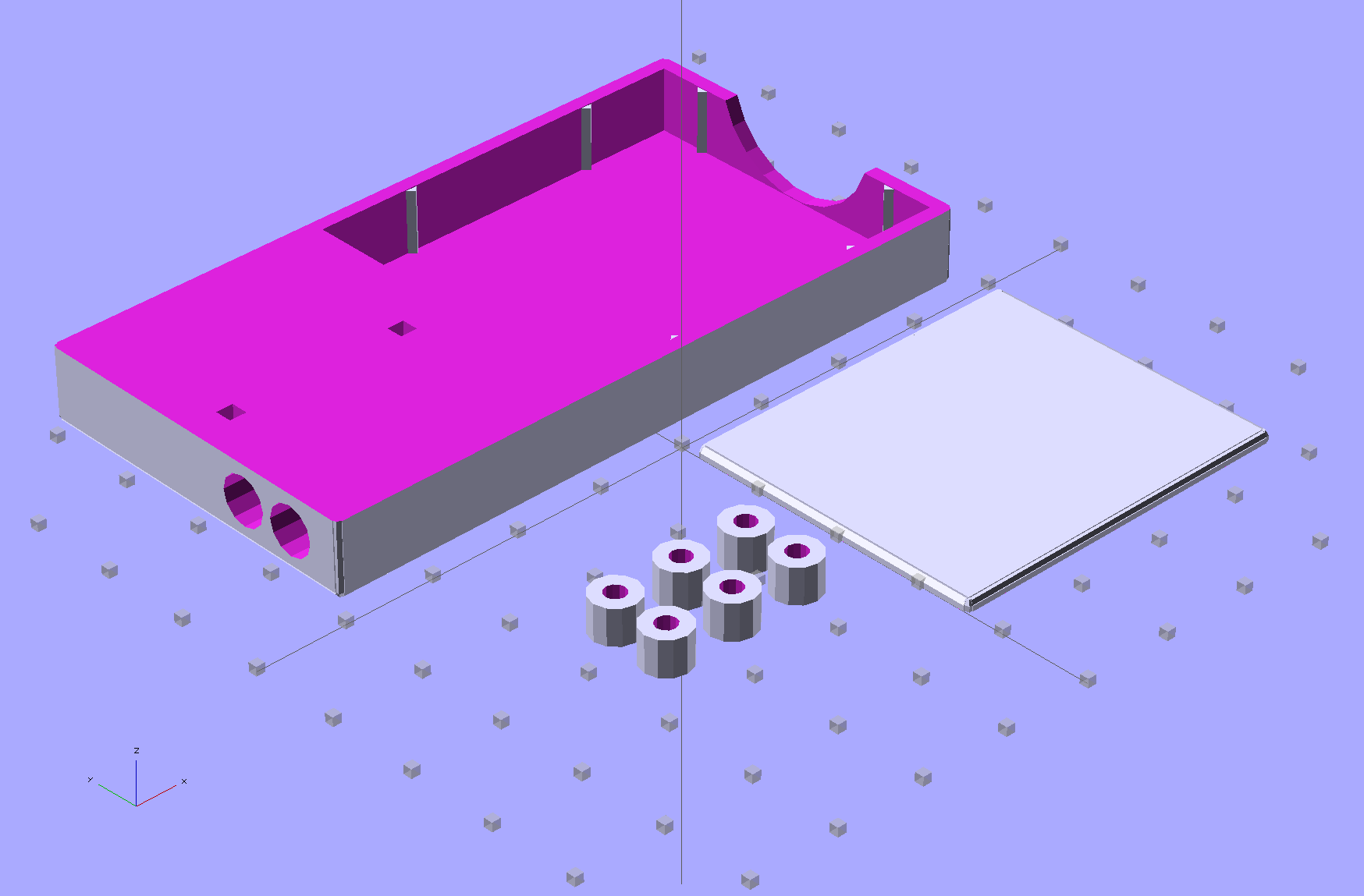
    The build layout includes extra retaining plugs, as they tend to go walkabout under the bench:

    NB-6L Holder - build layout
    NB-6L Holder – build layout

    Add a dab of PVC cement with THF inside the holes and the plugs push firmly into place:

    Canon NB-6L holder - pin retaining plugs - detail
    Canon NB-6L holder – pin retaining plugs – detail

    I loves me my 3D printer…

    The OpenSCAD source code:

    // Holder for Canon NB-6L Li-Ion battery
    // Ed Nisley KE4ZNU January 2013
    
    include <MCAD/boxes.scad>
    
    // Layout options
    
    Layout = "Plugs";					//  Show Build Fit Case Lid Pins Plugs AlignPins
    
    //- Extrusion parameters - must match reality!
    //  Print with +2 shells and 3 solid layers
    
    ThreadThick = 0.20;
    ThreadWidth = 0.40;
    
    HoleWindage = 0.2;
    
    function IntegerMultiple(Size,Unit) = Unit * ceil(Size / Unit);
    
    Protrusion = 0.1;			// make holes end cleanly
    
    inch = 25.4;
    
    BuildOffset = 3.0;			// clearance for build layout
    
    Gap = 8.0;					// separation for Fit parts
    
    //- Battery dimensions - rationalized from several samples
    //  Coordinate origin at battery corner by contact plates on bottom surface
    
    BatteryLength = 42.5;
    BatteryWidth = 35.5;
    BatteryThick =  7.0;
    
    ContactWidth = 2.10;
    ContactLength = 4.10;
    ContactRecess = 0.85;
    
    ContactOC = 3.18;			// center-to-center across contact face
    ContactOffset = 4.45;		// offset from battery edge
    ContactHeight = 3.05;		// offset from battery bottom plane
    
    AlignThick = 2.8;			// alignment recesses on contact face
    AlignDepth = 2.0;			// into face
    AlignWidth1 = 0.7;			// across face at contacts
    AlignWidth2 = 2.0;			//  ... other edge
    
    //- Pin dimensions
    
    PinTipDia = 1.6;
    PinTipLength = 10.0;
    
    PinTaperLength = 2.3;
    
    PinShaftDia = 2.4;
    PinShaftLength = 6.8;
    
    PinFerruleDia = 3.1;
    PinFerruleLength = 2.0;
    
    PinLength = PinTipLength + PinTaperLength + PinShaftLength + PinFerruleLength;
    
    ExtendRelax = 1.5 + ContactRecess;		// pin extension when no battery is present
    ExtendOvertravel = 1.0;					//  ... beyond engaged position
    
    //- Spring dimensions
    
    SpringDia = 3.1;						// coil OD
    SpringMax = 9.3;
    SpringLength = SpringMax - 0.3;			// slightly compressed
    SpringMin = 4.5;
    
    SpringPlugOD = IntegerMultiple(5.0,ThreadWidth);		// plug retaining the spring
    SpringPlugID = 2.0;
    SpringPlugLength = IntegerMultiple(4.0,ThreadWidth);
    SpringPlugSides = 3*4;
    
    SpringTravel = ExtendRelax + ExtendOvertravel;
    
    //- Holder dimensions
    
    GuideRadius = ThreadWidth;						// friction fit ridges
    GuideOffset = 10;
    WallThick = 4*ThreadWidth;						// holder sidewalls
    
    BaseThick = 6*ThreadThick;			// bottom of holder to bottom of battery
    TopThick = 6*ThreadThick;			// top of battery to top of holder
    
    ThumbRadius = 10.0;			// thumb opening at end of battery
    
    CornerRadius = 3*ThreadThick;			// nice corner rounding
    
    CaseLength = SpringPlugLength + SpringLength + PinLength - ExtendRelax
    			+ BatteryLength + GuideRadius + WallThick;
    CaseWidth = 2*WallThick + 2*GuideRadius + BatteryWidth;
    CaseThick = BaseThick + BatteryThick + TopThick;
    
    AlignPinOD = 1.75;			// lid alignment pins - filament snippets
    AlignPinLength = 5.0;
    AlignPinInset = 7.0;
    
    //- XY origin at front left battery corner, Z on platform below that
    
    CaseLengthOffset = -(SpringPlugLength + SpringLength + PinLength - ExtendRelax);
    CaseWidthOffset = -(WallThick + GuideRadius);
    CaseThickOffset = BaseThick;
    
    LidLength = ExtendRelax - CaseLengthOffset;
    
    echo(str("Contact pin tip dia: ",PinTipDia));
    echo(str("Drill depth to taper end: ",
    		 (SpringPlugLength + SpringLength + PinFerruleLength + PinShaftLength + PinTaperLength),
    		 " -- Dia: ",PinShaftDia));
    echo(str("            to ferrule end: ",
    		  (SpringPlugLength + SpringLength + PinFerruleLength),
    		 " -- Dia: ",PinFerruleDia));
    echo(str("            to plug end: ",SpringPlugLength,
    		 " -- Dia: ",SpringPlugOD));
    
    //----------------------
    // Useful routines
    
    module PolyCyl(Dia,Height,ForceSides=0) {			// based on nophead's polyholes
    
      Sides = (ForceSides != 0) ? ForceSides : (ceil(Dia) + 2);
    
      FixDia = Dia / cos(180/Sides);
    
      cylinder(r=(FixDia + HoleWindage)/2,
               h=Height,
    	   $fn=Sides);
    }
    
    module ShowPegGrid(Space = 10.0,Size = 1.0) {
    
      Range = floor(50 / Space);
    
    	for (x=[-Range:Range])
    	  for (y=[-Range:Range])
    		translate([x*Space,y*Space,Size/2])
    		  %cube(Size,center=true);
    
    }
    
    //-------------------
    
    //-- Guides for tighter friction fit
    
    module Guides() {
      	  translate([GuideOffset,-GuideRadius,CaseThickOffset])
    		PolyCyl(2*GuideRadius,(BatteryThick - Protrusion),4);
    	  translate([GuideOffset,(BatteryWidth + GuideRadius),CaseThickOffset])
    		PolyCyl(2*GuideRadius,(BatteryThick - Protrusion),4);
    	  translate([(BatteryLength - GuideOffset),-GuideRadius,CaseThickOffset])
    		PolyCyl(2*GuideRadius,(BatteryThick - Protrusion),4);
    	  translate([(BatteryLength - GuideOffset),(BatteryWidth + GuideRadius),CaseThickOffset])
    		PolyCyl(2*GuideRadius,(BatteryThick - Protrusion),4);
    	  translate([(BatteryLength + GuideRadius),GuideOffset/2,CaseThickOffset])
    		PolyCyl(2*GuideRadius,(BatteryThick - Protrusion),4);
    	  translate([(BatteryLength + GuideRadius),(BatteryWidth - GuideOffset/2),CaseThickOffset])
    		PolyCyl(2*GuideRadius,(BatteryThick - Protrusion),4);
    
    }
    
    //-- Contact pins (holes therefore)
    
    module PinShape() {
    
      union() {
    	cylinder(r=(PinTipDia + HoleWindage)/2,h=(PinTipLength + Protrusion),$fn=6);
    
    	translate([0,0,PinTipLength])
    	  cylinder(r=(PinShaftDia + HoleWindage)/2,
    			   h=(PinTaperLength + PinShaftLength + Protrusion),$fn=6);
    
    	translate([0,0,(PinLength - PinFerruleLength)])
    	  cylinder(r=(PinFerruleDia + HoleWindage)/2,
    				h=(PinFerruleLength + Protrusion),$fn=6);
    
    	translate([0,0,(PinLength)])
    	  cylinder(r=(SpringDia + HoleWindage)/2,
    				h=(SpringLength + Protrusion),$fn=6);
    
    	translate([0,0,(PinLength + SpringLength - HoleWindage)])	// windage for hole length
    	  cylinder(r=(SpringPlugOD + HoleWindage)/2,h=3*SpringPlugLength,$fn=SpringPlugSides);
    
    //	  translate([0,0,(PinLength + SpringLength + SpringPlugLength)])
    //	  cylinder(r=(SpringPlugOD + HoleWindage)/2,h=2*SpringPlugLength,$fn=SpringPlugSides);	// extend hole
      }
    
    }
    
    module PinAssembly() {
    
      translate([ExtendRelax,ContactOffset,CaseThickOffset + ContactHeight]) {
    	rotate([0,270,0]) {
    	  PinShape();												// pins
    	  translate([0,(2*ContactOC),0])
    		PinShape();
    	}
      }
    
    }
    
    //-- Alignment pins
    
    module AlignPins() {
    
    	for (x=[-1,1])
    		translate([x*(LidLength - 2*AlignPinInset)/2,0,0])
    			rotate(45)
    			PolyCyl(AlignPinOD,AlignPinLength);
    }
    
    //-- Case with origin at battery corner
    
    module Case() {
    
      difference() {
    
    	union() {
    
    	  difference() {
    		translate([(CaseLength/2 + CaseLengthOffset),
    				  (CaseWidth/2 + CaseWidthOffset),
    				  (CaseThick/2)])
    		  roundedBox([CaseLength,CaseWidth,CaseThick],CornerRadius); 	// basic case shape
    
    		translate([-ExtendOvertravel,-GuideRadius,CaseThickOffset])
    		  cube([(BatteryLength + GuideRadius + ExtendOvertravel),
    				(BatteryWidth + 2* GuideRadius),
    				(BatteryThick + Protrusion)]);						// battery space
    
    	  }
    
    	  Guides();
    
    	  translate([-ExtendOvertravel,-GuideRadius,BaseThick])
    		cube([(AlignDepth + ExtendOvertravel),
    			  (AlignWidth1 + GuideRadius),
    			  AlignThick]);											// alignment blocks
    	  translate([-ExtendOvertravel,
    				 (BatteryWidth - AlignWidth2),
    				 BaseThick])
    		cube([(AlignDepth + ExtendOvertravel),
    			  (AlignWidth2 + GuideRadius),
    			  AlignThick]);
    
    	}
    
    	translate([(-ExtendOvertravel),
    			   (CaseWidthOffset - Protrusion),
    			   (CaseThickOffset + BatteryThick)])
    	  cube([CaseLength,
    		    (CaseWidth + 2*Protrusion),
    		    (TopThick + Protrusion)]);								// battery access
    
    	translate([(CaseLengthOffset - Protrusion),
    			   (CaseWidthOffset - Protrusion),
    			   (CaseThickOffset + BatteryThick)])
    	  cube([(CaseLength + 2*Protrusion),
    		    (CaseWidth + 2*Protrusion),
    		    (TopThick + Protrusion)]);								// battery insertion allowance
    
    	translate([(BatteryLength - Protrusion),
    			    (CaseWidth/2 + CaseWidthOffset),
    			    (CaseThickOffset + ThumbRadius)])
    	  rotate([90,0,0])
    		rotate([0,90,0])
    		  cylinder(r=ThumbRadius,
    				   h=(WallThick + GuideRadius + 2*Protrusion),
    				   $fn=22);											// remove thumb notch
    
    	PinAssembly();
    
    	translate([-LidLength/2,BatteryWidth/2,CaseThick - TopThick - (AlignPinLength - TopThick/2)])
    		AlignPins();
      }
    
    }
    
    module Lid() {
    
      difference() {
    	translate([0,0,(CaseThick/2 - BaseThick - BatteryThick)])
    	  roundedBox([LidLength,
    				 CaseWidth,CaseThick],CornerRadius);
    
    	translate([0,0,-(CaseThick/2)])
    	  cube([(LidLength + 2*Protrusion),
    		    (CaseWidth + 2*Protrusion),
    		    (CaseThick)],center=true);
    
    	translate([-ExtendRelax,0,-(AlignPinLength - TopThick/2)])
    		AlignPins();
      }
    
    }
    
    module PlugShape() {
    
      difference() {
    	cylinder(r=SpringPlugOD/2,h=SpringPlugLength,$fn=SpringPlugSides);
    	translate([0,0,-Protrusion])
    	  PolyCyl(SpringPlugID,(SpringPlugLength + 2*Protrusion),SpringPlugSides);
      }
    }
    
    module Plugs() {
      translate([0,ContactOC,0])
    	PlugShape();
      translate([0,-ContactOC,0])
    	PlugShape();
    }
    
    //-------------------
    // Build it!
    
    ShowPegGrid();
    
    if (Layout == "Case")
      Case();
    
    if (Layout == "Lid")
      Lid();
    
    if (Layout == "Plugs")
    	for (i=[-1:1])
    		translate([i*1.5*SpringPlugOD,0,0])
    			Plugs();
    
    if (Layout == "Pins")
      PinShape();
    
    if (Layout == "AlignPins")
      AlignPins();
    
    if (Layout == "Show") {								// reveal pin assembly
      difference() {
    	Case();
    
    	translate([(CaseLengthOffset - Protrusion),
    			   (CaseWidthOffset - Protrusion + WallThick + ContactOffset + ContactOC),
    			   (BaseThick + ContactHeight)])
    	  cube([(-CaseLengthOffset + Protrusion),
    			 (CaseWidth + 2*Protrusion),
    			 CaseThick + BaseThick - ContactHeight + Protrusion]);
    
    	translate([(CaseLengthOffset - Protrusion),
    			   (CaseWidthOffset - Protrusion),
    			   -Protrusion])
    	  cube([(-CaseLengthOffset + Protrusion),
    			 (WallThick + GuideRadius + ContactOffset + Protrusion),
    			 CaseThick]);
      }
    
      translate([ExtendRelax,ContactOffset,(CaseThickOffset + ContactHeight)]) {	// pins
    	rotate([0,270,0]) {
    	  %PinShape();
    //	  translate([0,(2*ContactOC),0])
    //		%PinShape();
    	}
      }
    
      translate([CaseLengthOffset,ContactOffset,(CaseThickOffset + ContactHeight)])
    	rotate([0,90,0])
    	  PlugShape();
    }
    
    if (Layout == "Build") {
      translate([-(CaseLength/2 + CaseLengthOffset),-(CaseWidthOffset - BuildOffset),0])
    	Case();
      translate([CaseWidth/2,(CaseLengthOffset/2 - BuildOffset),0])
    	rotate([0,0,90])
    	  Lid();
      for (i=[-1:1])
    	translate([CaseLengthOffset/2 + i*1.5*SpringPlugOD,-CaseWidth/2,0])
    		Plugs();
    }
    
    if (Layout == "Fit") {
      Case();
      translate([(-LidLength/2 + ExtendRelax),
    			(CaseWidth/2 + CaseWidthOffset),
    			(BaseThick + BatteryThick + Gap)])
    	  Lid();
      translate([ExtendRelax,ContactOffset,CaseThickOffset + ContactHeight]) {	// pins
    	rotate([0,270,0]) {
    	  %PinShape();
    	  translate([0,(2*ContactOC),0])
    		%PinShape();
    	}
      }
    
      translate([CaseLengthOffset,
    			(ContactOffset + ContactOC),
    			(CaseThickOffset + ContactHeight)])
      rotate([0,90,0])
    	Plugs();
    
      translate([-LidLength/2,BatteryWidth/2,CaseThick])
    #	AlignPins();
    
    }
    
    
  • Thing-O-Matic 286 Conversion: Marlin Firmware Tweaks

    Azteeg X3 - inside TOM286
    Azteeg X3 – inside TOM286

    Although the TOM286 conversion won’t need any fancy firmware, I forked Marlin’s Github repository and created a TOM286 branch based on the Marlin_v1 branch for the Azteeg X3 modifications; in theory, we can blend in future Marlin updates without too much hassle.

    The Pronterface serial port tops out at 115200, so that’s a mandatory change right up front. [grin]

    Marlin has a motherboard definition for an Azteeg X3 (type 67), but without the optional thermocouple inputs. I added motherboard 671, following the lead of the Megatronics board definitions (types 70, 701, and 702). In addition to the changes below, any test for motherboard 67 now includes 671, as the other pins and suchlike (should) be the same.

    Motherboard 671 selects new pin definitions for the temperature inputs in pins.h:

      #if MOTHERBOARD == 671
    	#define TEMP_0_PIN         11   // TC1 on shield
    	#define TEMP_1_PIN          4   // TC2 on shield
    	#define TEMP_2_PIN         13   // T0 thermistor on Azteeg X3 motherboard
      #else
        #define TEMP_0_PIN         13   // ANALOG NUMBERING
        #define TEMP_1_PIN         15   // ANALOG NUMBERING
        #define TEMP_2_PIN         -1   // ANALOG NUMBERING
    #endif
    

    There’s now a TCOUPLE_AMP_TYPE definition in Configuration.h to select AD595 or AD849x thermocouple interfaces:

    // Thermocouple sensor amplifier type
    //  0 = AD595 gain = 10 mV/C
    //  1 = AD849[4567] gain = 5 mV/C
    
    #define TCOUPLE_AMP_TYPE 1
    

    That picks the proper offset and gain definitions in Configuration_adv.h:

    // The AD849[4567] has 5 mv/C gain, half that of the AD595, and requires _GAIN = 2
    
    #if TCOUPLE_AMP_TYPE == 1
      #define TEMP_SENSOR_AD595_OFFSET 0.0
      #define TEMP_SENSOR_AD595_GAIN   2.0
    #else
      #define TEMP_SENSOR_AD595_OFFSET 0.0
      #define TEMP_SENSOR_AD595_GAIN   1.0
    #endif
    

    With those in hand, these temperature sensor selections in Configuration.h will work:

    #define TEMP_SENSOR_0 -1
    #define TEMP_SENSOR_1 0
    #define TEMP_SENSOR_2 0
    #define TEMP_SENSOR_BED 1
    

    I tweaked the temperature limits and preheat settings; the absolute minimum temperatures are now 10 °C, although I have not verified that a disconnected thermocouple or thermistor will actually trip that limit.

    Given the completely arbitrary stepper motor wiring connections, I set all the direction inversions to false and then swapped wires to make the motors turn in the proper direction.

    I enabled EEPROM_SETTINGS, but haven’t verified that values can actually store and recall themselves.

    The XYZ=0 origin is in the middle of the platform, just where I like it, but that will require some fine tuning:

    // Travel limits after homing
    #define X_MAX_POS 55
    #define X_MIN_POS -50
    #define Y_MAX_POS 60
    #define Y_MIN_POS -60
    #define Z_MAX_POS 120
    #define Z_MIN_POS 0
    

    I think it’s possible to use the Z_SAFE_HOMING position to force Z-minimum homing on the platform height switch I built for the original firmware, but that operation also seems to be tied in with the three-point auto-leveling firmware and rotating switch assembly. Right now, the firmware homes to the Z-max switch as a stock Thing-O-Matic should, but I’ve never liked that arrangement; don’t start with me, you know how I get.

    I backed the speeds and accelerations down from the values I’d been using, mostly because the driver hardware and currents are different:

    // Computing steps/mm
    // for XY = (motor steps/rev * microstepping) / (pulley teeth * tooth pitch)
    // for  Z = (motor steps/rev * microstepping) / (screw lead) // for  E = (motor steps/rev * microstepping) / (gear ratio * drive circumference) //  make sure ratios use floating point to avoid integer division!
    #define DEFAULT_AXIS_STEPS_PER_UNIT   {(200*16)/(17*2.0), (200*16)/(17*2.0), (200*8)/8.0, (200*4)/((7*30.23)/51)}
    #define DEFAULT_MAX_FEEDRATE          {5000/60, 5000/60, 1500/60, 4000/60}    // (mm/sec)
    #define DEFAULT_MAX_ACCELERATION      {5000, 2500, 1000, 250}    // X, Y, Z, E maximum start speed for accelerated moves. E default values are good for skeinforge 40+, for older versions raise them a lot.
    
    #define DEFAULT_ACCELERATION          10000   // X, Y, Z and E max acceleration in mm/s^2 for printing moves
    #define DEFAULT_RETRACT_ACCELERATION  10000   // X, Y, Z and E max acceleration in mm/s^2 for retracts


    I’m not sure how to calculate the “jerk” settings, but taken as the maximum un-accelerated speed, these seem conservative:

    // The speed change that does not require acceleration (i.e. the software might assume it can be done instantaneously)
    #define DEFAULT_XYJERK                25    // (mm/sec)
    #define DEFAULT_ZJERK                 5    // (mm/sec)
    #define DEFAULT_EJERK                 5     // (mm/sec)
    

    More tuning is in order; that should at least start it up.