Ed Nisley's Blog: Shop notes, electronics, firmware, machinery, 3D printing, laser cuttery, and curiosities. Contents: 100% human thinking, 0% AI slop.
That can also come from a sensor failure, but it takes perfectly good movies. That’s the differential diagnosis for shutter failure, because movies don’t use the shutter.
The shutter still functions, in that peering into the lens shows the shutter closing as it takes a picture, so I suspect it’s gotten a bit sticky and slow over the years. None of the various shutter-priority speeds have any effect, which means that the shutter isn’t responding properly.
A quick read of the service manual shows the Field Replaceable Unit for this situation is the entire lens assembly. Back in the day, a new lens assembly came with its own calibration constants on a floppy disk that you’d install with Casio’s service program (the latest version ran with Windows 98!) using a special USB communication mode triggered by a Vulcan Nerve Pinch on the camera. At this late date, none of that stuff remains available.
While I could take the camera apart and crack the lens capsule open, I doubt that would make it better and, in this case, ending up with a crappy camera doesn’t count for much. Extracting the lens assembly requires dismantling the entire thing, which, frankly, doesn’t seem worth the effort…
That image is number 7915: so it’s taken a bit over two images per day for the last nine years. I can’t swear the counter has never been reset, but that seems about right.
The burner in our oven failed in December 2006, probably because the charred remains of an insect produced a hotspot:
Burned Oven Tube Overview
That replacement burner came with its own igniter that failed after 8.5 years, with symptoms of slow oven ignition and the occasional smell of propane.
In normal operation, the igniter element glows yellow-hot for a minute or so before the valve opens, gas flows over the igniter, there’s a muffled whoomf, and the oven begins heating. The igniter remains powered as long as the oven is on, emitting a baleful yellow glare through the slots in the oven’s lower cover.
It consists of a ceramic base holding a stout resistance heater that apparently suffers from increasing resistance as it ages, reducing the current to the point where it won’t activate the gas valve.
I didn’t know that, either, but Google sees all, knows all, and tells most.
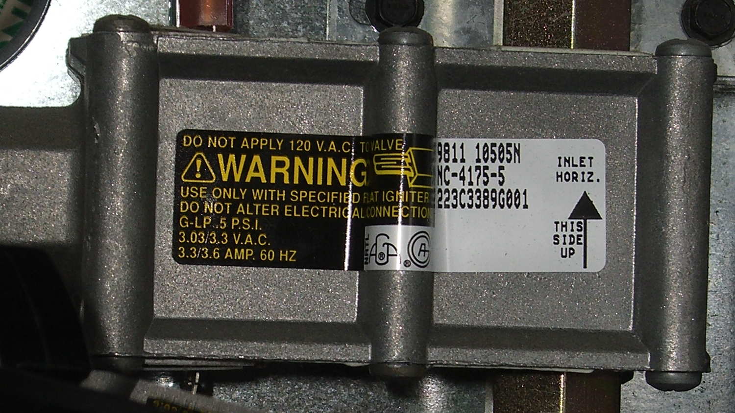
The gas valve label says it requires 3.3 to 3.6 A from the heater to turn on the gas:
Kenmore range oven gas valve – data plate
But the old heater was good for barely 2.6 A (there’s a bit of parallax in this view):
Kenmore range oven gas valve – weak igniter current
Igniters range from $18 to upwards of $60 on Amazon, so I picked the cheapest one, waited two days, installed it, and measured 3.5 A at First Light, down to a bit over 3.0 A at running temperature. That’s on the low side of the valve’s spec, but it seems happier with an extra half amp.
We’ll see how long this igniter lasts; maybe next time I’ll double my spend…
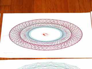
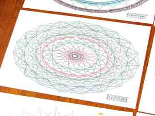
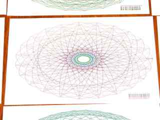
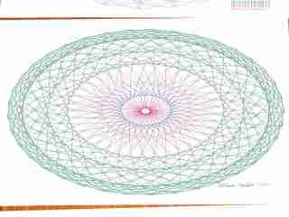
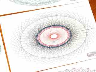
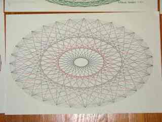
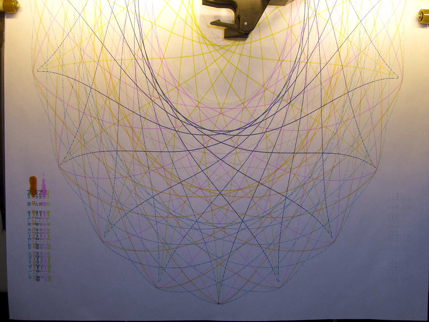
A gallery of SuperFormula plots, resized / contrast stretched / ruthlessly compressed (clicky for more dots):
SuperFormula Plot – 01
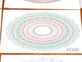
SuperFormula Plot – 02
SuperFormula Plot – 03
SuperFormula Plot – 04
SuperFormula Plot – 05
SuperFormula Plot – 06
SuperFormula Plot – 07
SuperFormula Plot – 08
SuperFormula Plot – 09
SuperFormula Plot – 10
SuperFormula Plot – 11
SuperFormula Plot – 12
SuperFormula Plot – 13
SuperFormula Plot – 14
SuperFormula Plot – 15
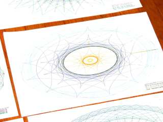
The gray one at the middle-bottom suffered from that specular reflection; the automagic contrast stretch couldn’t boost the paper with those burned pixels in the way.
Those sheets all have similar plots on the back, some plots used refilled pens that occasionally bled through the paper, others have obviouslybad / dry pens, and you’ll spot abrupt color changes where I swapped out a defunct pen on the fly, but they should give you an idea of the variations.
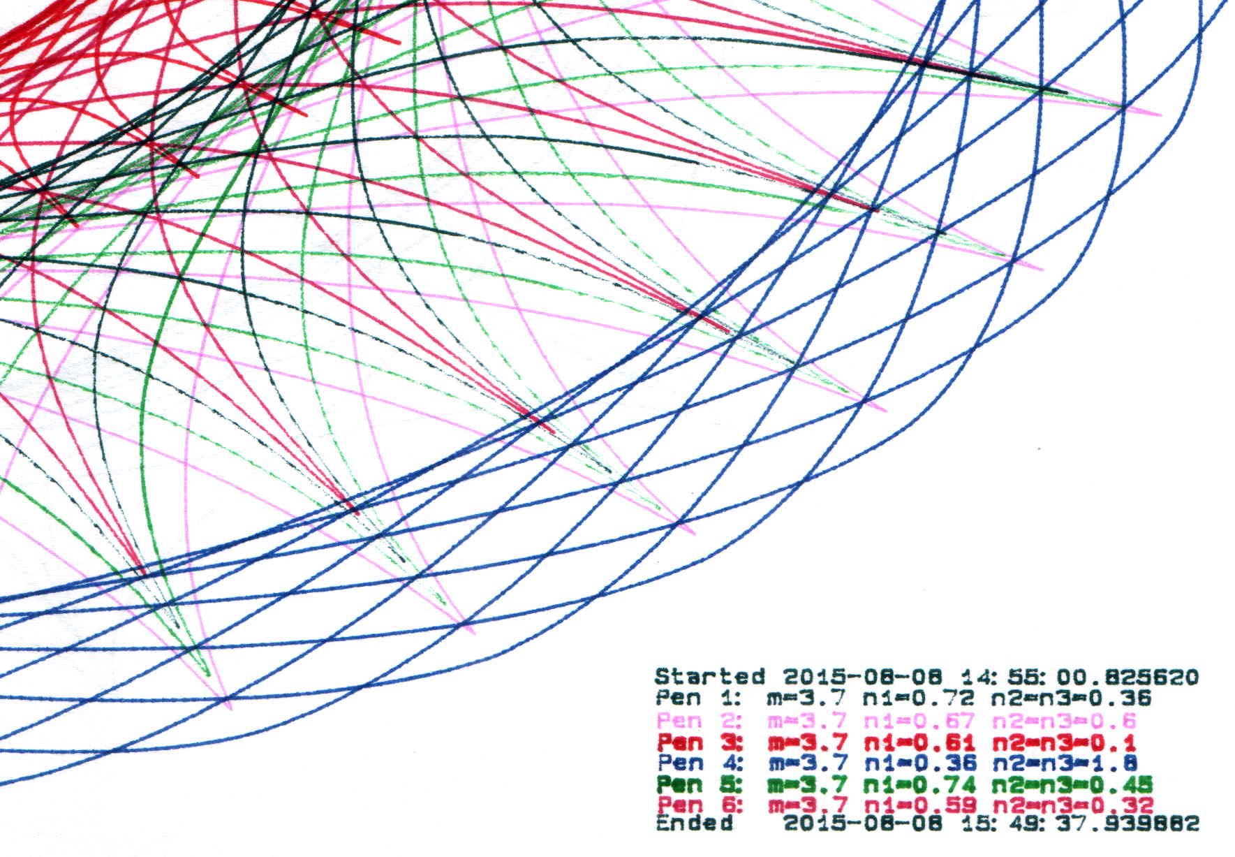
The more recent plots have a legend in the right bottom corner with coefficients and timestamps:
SuperFormula Plot – legend detail
Limiting the pen speed to 10 cm/s (down from the default 38.1 cm/s = 15.00 inch/s) affects only the outermost segments of the spikes; down near the dense center, the 9600 b/s serial data rate limits the plotting speed. Plotting slowly helps old pens with low flow rates draw reasonably dense lines.
Each plot takes an hour, which should suffice for most dog-and-pony events.
I fill a trio of Python lists with useful coefficient values, then choose random elements for each plot: a single value of m determines the number of points for all six traces, then six pairs of values set n1 and n2=n3. The lists are heavily weighted to produce spiky traces, rather than smooth ovals, so the “random” list selections aren’t uniformly distributed across the full numeric range of the values.
Because the coefficient lists contain fixed values, the program can produce only a finite number of different plots, but I’m not expecting to see any duplicates. You can work out the possibilities by yourself.
The modified Chiplotle demo code bears little resemblance to the original:
from chiplotle import *
from math import *
from datetime import *
import random

def superformula_polar(a, b, m, n1, n2, n3, phi):
   ''' Computes the position of the point on a
   superformula curve.
   Superformula has first been proposed by Johan Gielis
   and is a generalization of superellipse.
   see: http://en.wikipedia.org/wiki/Superformula
   Tweaked to return polar coordinates
   '''

   t1 = cos(m * phi / 4.0) / a
   t1 = abs(t1)
   t1 = pow(t1, n2)

   t2 = sin(m * phi / 4.0) / b
   t2 = abs(t2)
   t2 = pow(t2, n3)

   t3 = -1 / float(n1)
   r = pow(t1 + t2, t3)
   if abs(r) == 0:
      return (0,0)
   else:
 #     return (r * cos(phi), r * sin(phi))
     return (r,phi)


def supershape(width, height, m, n1, n2, n3,
   point_count=10*1000, percentage=1.0, a=1.0, b=1.0, travel=None):
   '''Supershape, generated using the superformula first proposed
   by Johan Gielis.

   - `points_count` is the total number of points to compute.
   - `travel` is the length of the outline drawn in radians.
      3.1416 * 2 is a complete cycle.
   '''
   travel = travel or (10*2*pi)

   ## compute points...
   phis = [i * travel / point_count
      for i in range(1 + int(point_count * percentage))]
   points = [superformula_polar(a, b, m, n1, n2, n3, x) for x in phis]

   ## scale and transpose...
   path = [ ]
   for r, a in points:
      x = width * r * cos(a)
      y = height * r * sin(a)
      path.append(Coordinate(x, y))

   return Path(path)


## RUN DEMO CODE

if __name__ == '__main__':
   paperx = 8000
   papery = 5000
   tscale = 0.45
   numpens = 6
   m_list = [n/10.0 for n in [11, 13, 17, 19, 23, 29, 31, 37, 41, 43, 47, 53, 59]];   # prime/10 = number of spikes
   n1_list = [n/100.0 for n in range(15,75,1) + range(80,120,5) + range(120,200,10)]  # ring-ness 0.1 to 2.0, higher is larger diameter
   n2_list = [n/100.0 for n in range(10,50,1) + range(55,100,5) + range(110,200,10)]  # spike-ness 0.1 to 2.0, lower means spiky points
   paramlist = [[n1,n2] for n1 in random.sample(n1_list,numpens) for n2 in random.sample(n2_list,numpens)]
   if  not False:
     plt=instantiate_plotters()[0]
     plt.write('IN;')
#     plt.write(chr(27) + '.H200:')   # set hardware handshake block size
     plt.set_origin_center()
     plt.write(hpgl.SI(tscale*0.285,tscale*0.375))    # scale based on B size characters
     plt.write(hpgl.VS(10))                           # slow speed for those abrupt spikes
     pen = 1
     plt.select_pen(pen)
     plt.write(hpgl.PA([(paperx - 3000,-(papery - 600))]))
     plt.write(hpgl.LB("Started " + str(datetime.today())))
     m = random.choice(m_list)
     for n1, n2 in zip(random.sample(n1_list,numpens),random.sample(n2_list,numpens)):
        n3 = n2
        print "m: ", m, " n1: ", n1, " n2=n3: ", n2
        plt.write(hpgl.PA([(paperx - 3000,-(papery - 500 + 100*(pen - 1)))]))
        plt.select_pen(pen)
        plt.write(hpgl.LB("Pen " + str(pen) + ": m=" + str(m) + " n1=" + str(n1) + " n2=n3=" + str(n2)))
        e = supershape(paperx, papery, m, n1, n2, n3)
        plt.write(e)
        if pen < numpens:
            pen += 1
        else:
            pen = 1
     pen = 1
     plt.select_pen(pen)
     plt.write(hpgl.PA([(paperx - 3000,-(papery - 500 + 100*numpens))]))
     plt.write(hpgl.LB("Ended   " + str(datetime.today())))
     plt.select_pen(0)
   else:
     e = supershape(paperx, papery, 1.9, 0.8, 3, 3)
     io.view(e)
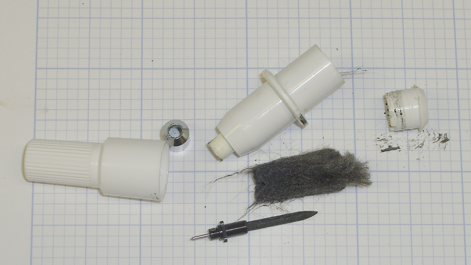
It turns out that the ceramic-tip plotter pens don’t come apart at the top of the flange as I expected. Instead, there’s a snug-fitting plug with a tapered top and an invisible joint at the end of the body tube:
HP7475A Plotter – ceramic pen – disassembled
Refilling a pair of defunct black ceramic pens didn’t bring them back to life: an ample supply of fresh black ink never made it from the fluff to the nib. Soaking the nibs + fiber shafts in 10% ethanol for a day created an unappetizing black vodka shot that did nothing to get the ink where it needed to be.
The right time to refill those pens would have been, oh, probably a decade or two ago…
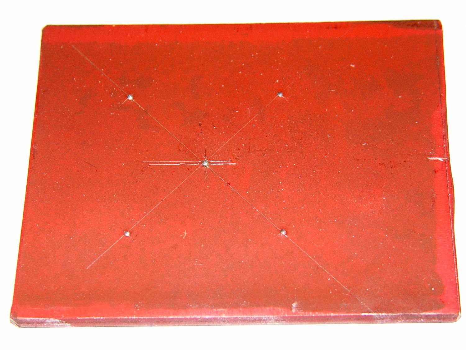
The Squidwrench Power Wheels Racer needed a mounting bracket for its DC motor, so Matt handed me a precut steel slab and some drawings. I did a manual layout to get a feel for the sizes:
Motor Mount – dye layout
Yes, it’s slightly rhomboid & irregular on the sides; it’ll be welded to a U-channel. The front edge is the straightest and I scribed a perpendicular datum line over on the right, from which to measure the motor center point.
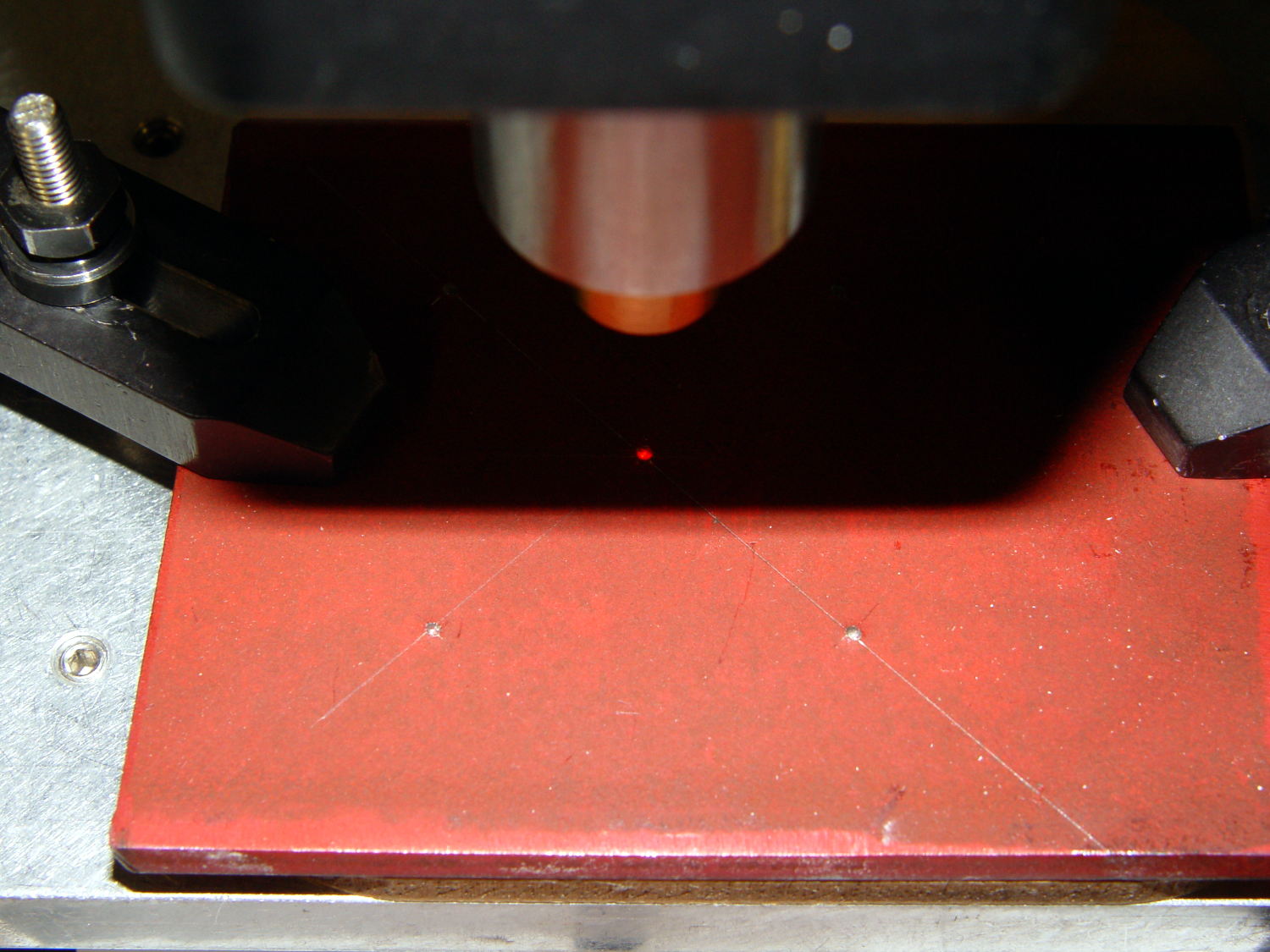
But then, realizing I’d have to mill the central hole anyway, I did what I should have done from the beginning and lined it up on the Sherline:
Motor Mount – Sherline laser centering
With the part zeroed at the center, everything has polar coordinates. The bolt holes are #10 on a 50 mm BCD, which is G0 @25^[45+90*i]. Rather than writing & debugging a program, I did it all by feeding manual instructions into the interpreter; the i gets typed as 0, 1, 2, and 3 by clicking on a previous command, backspacing, and retyping, which is both faster and easier than it sounds. The holes are drill cycles: G81 Z-7 R1 F30
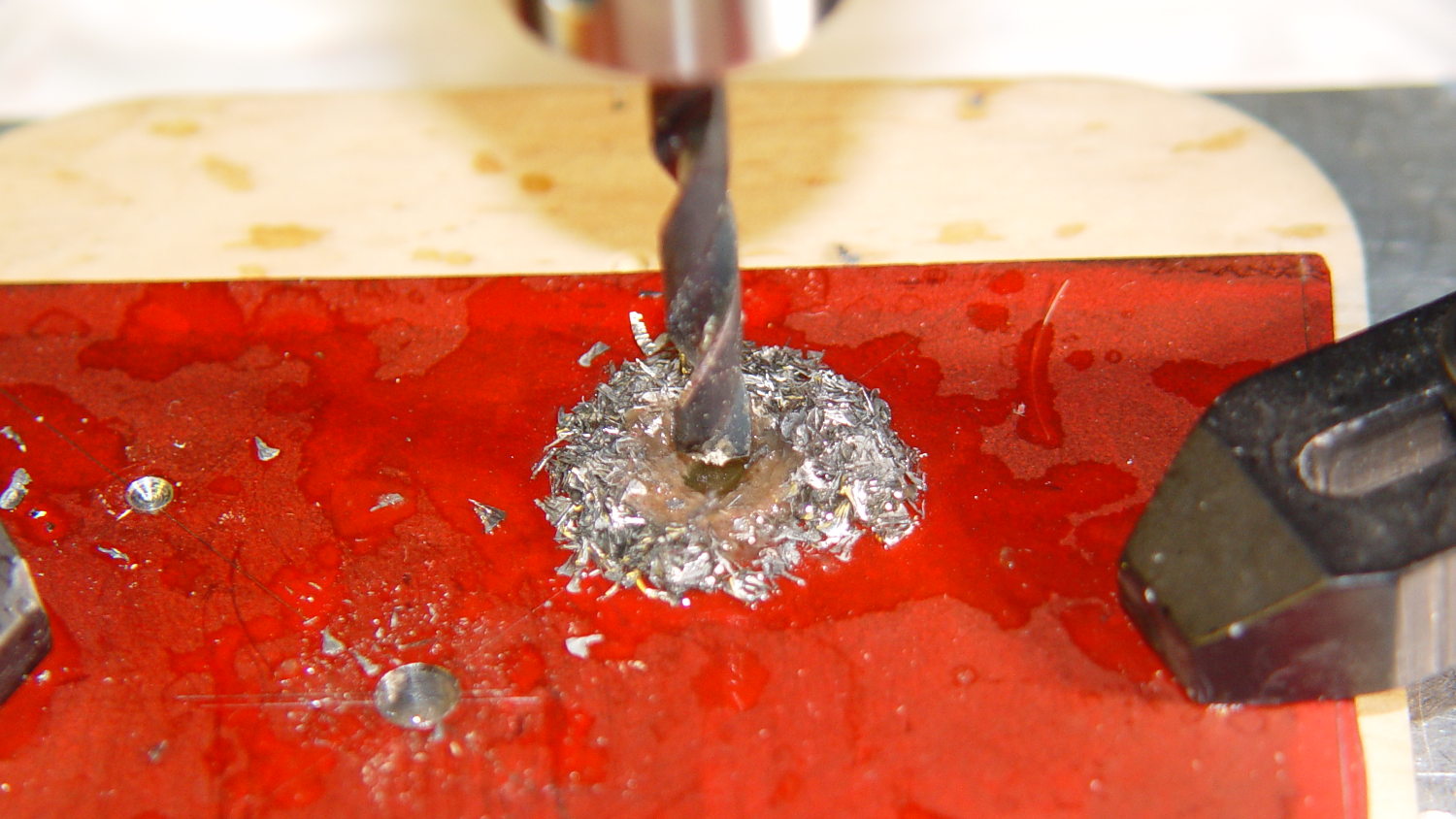
This being steel on a Sherline, the rule of thumb that says you can drill at 100x the drill diameter (in inch/min or mm/min, as appropriate) at 3000 RPM gets derated by at least factor of 10. I settled on 30 mm/min for a #10 drill (0.194 inch = 4.9 mm → 500 mm/min = hogwash) after trying the first hole at 50 mm/min:
Motor Mount – bolt holes
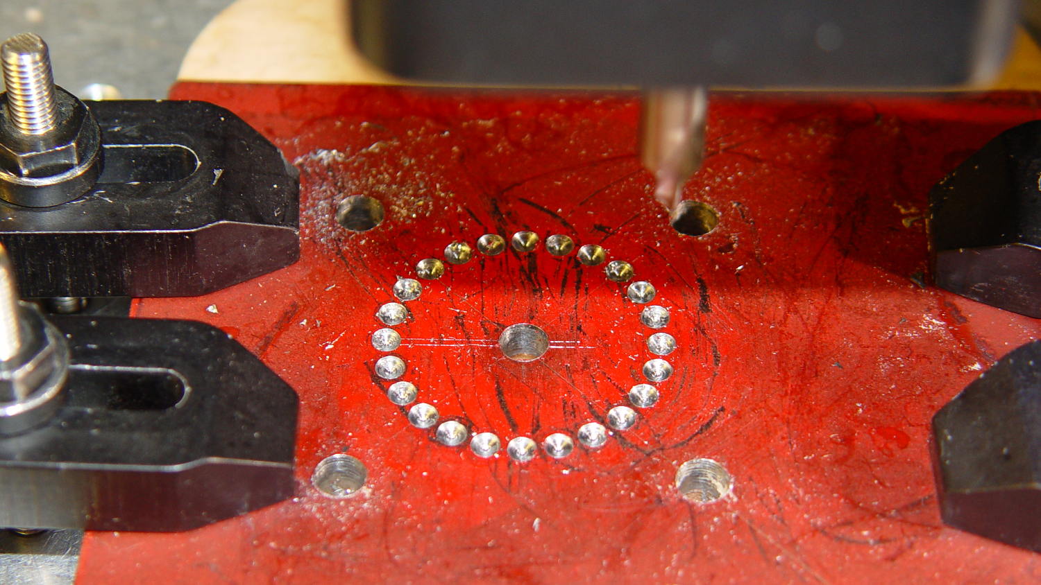
The least horrible way to cut out the hole for the motor mounting boss involved chain drilling to excavate the most steel with the least effort. These center drill points are at G0 @14 ^[15*i] with i in [0..23]:
Motor Mount – chain center drilling
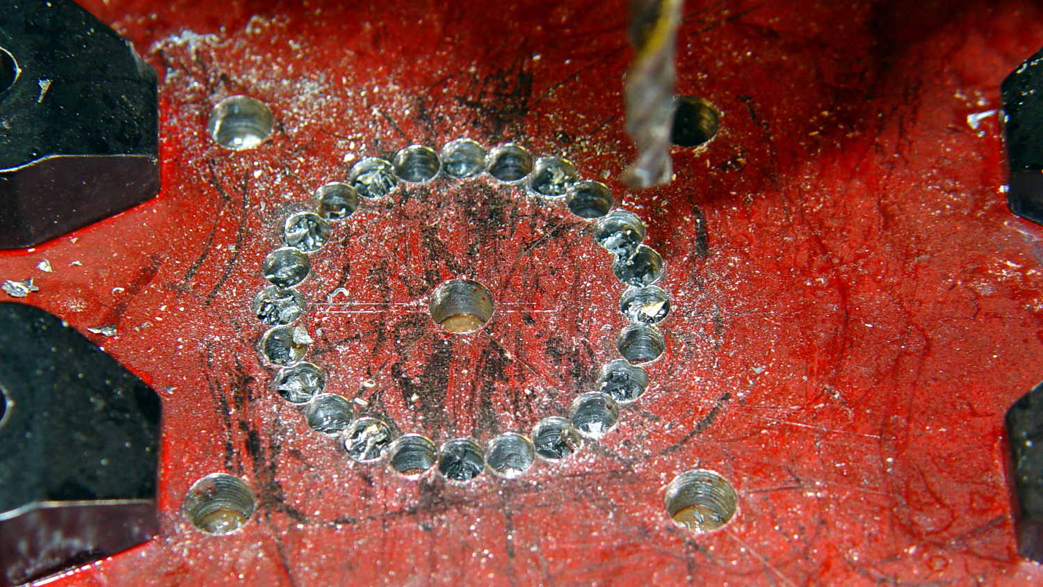
I drilled every even hole #27, then every odd hole #28, both at 50 mm/min, to get a thin web:
Motor Mount – chain drilled
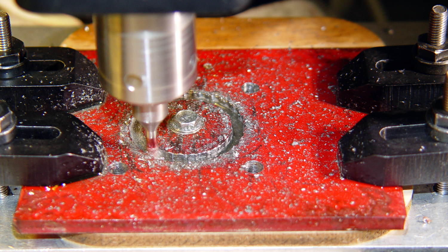
Then helix-mill downward with a 1/8 inch end mill at 1 mm per pass:
Motor Mount – helix milling
That started at 14 mm from the origin to match the hole circle: G3 I-14 F100 Z-1
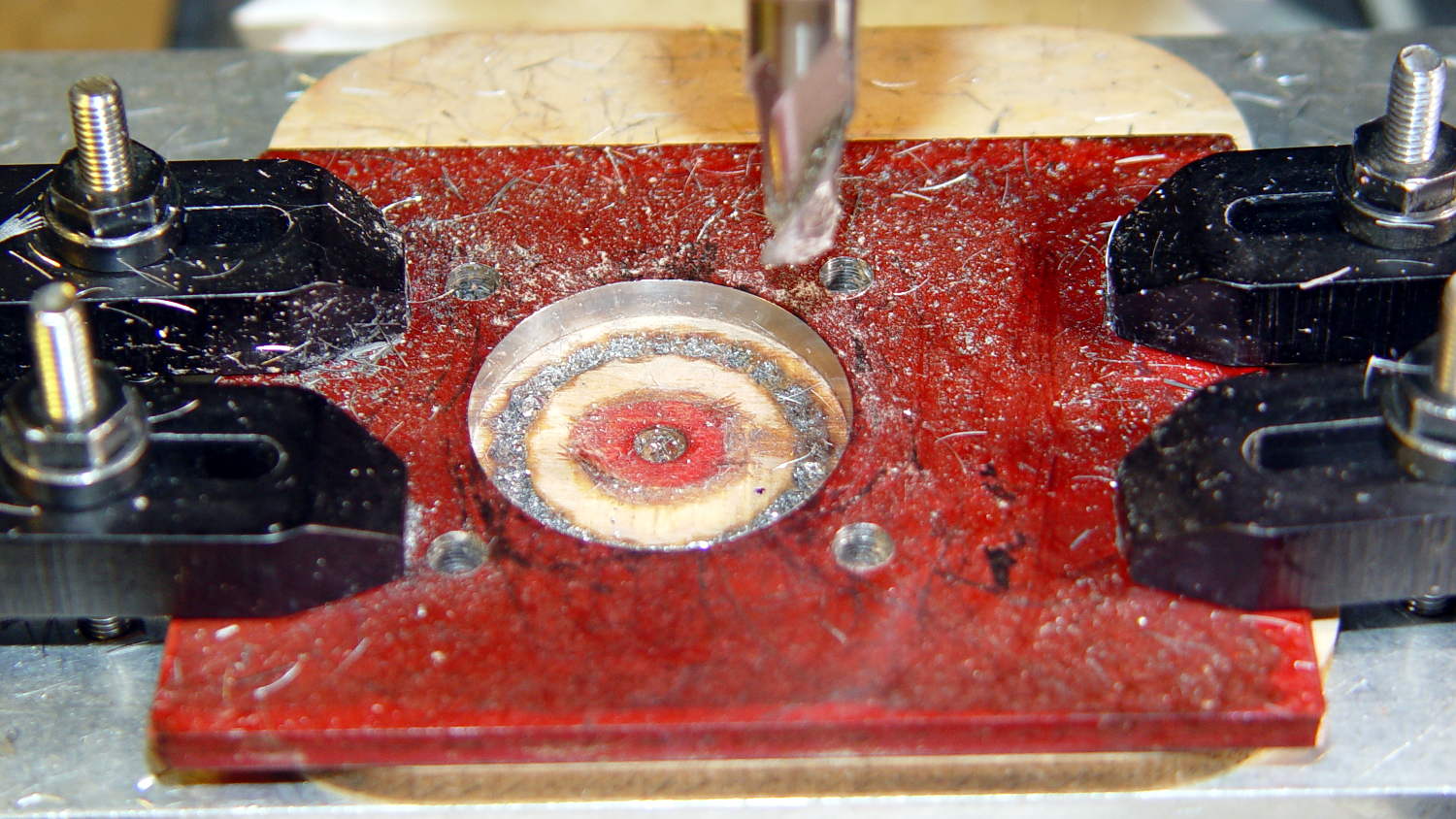
Then I switched to a 3/8 inch = 9.5 mm end mill to bring the hole up to size, ending with G3 I-12.75 F300
Motor Mount – center hole milled
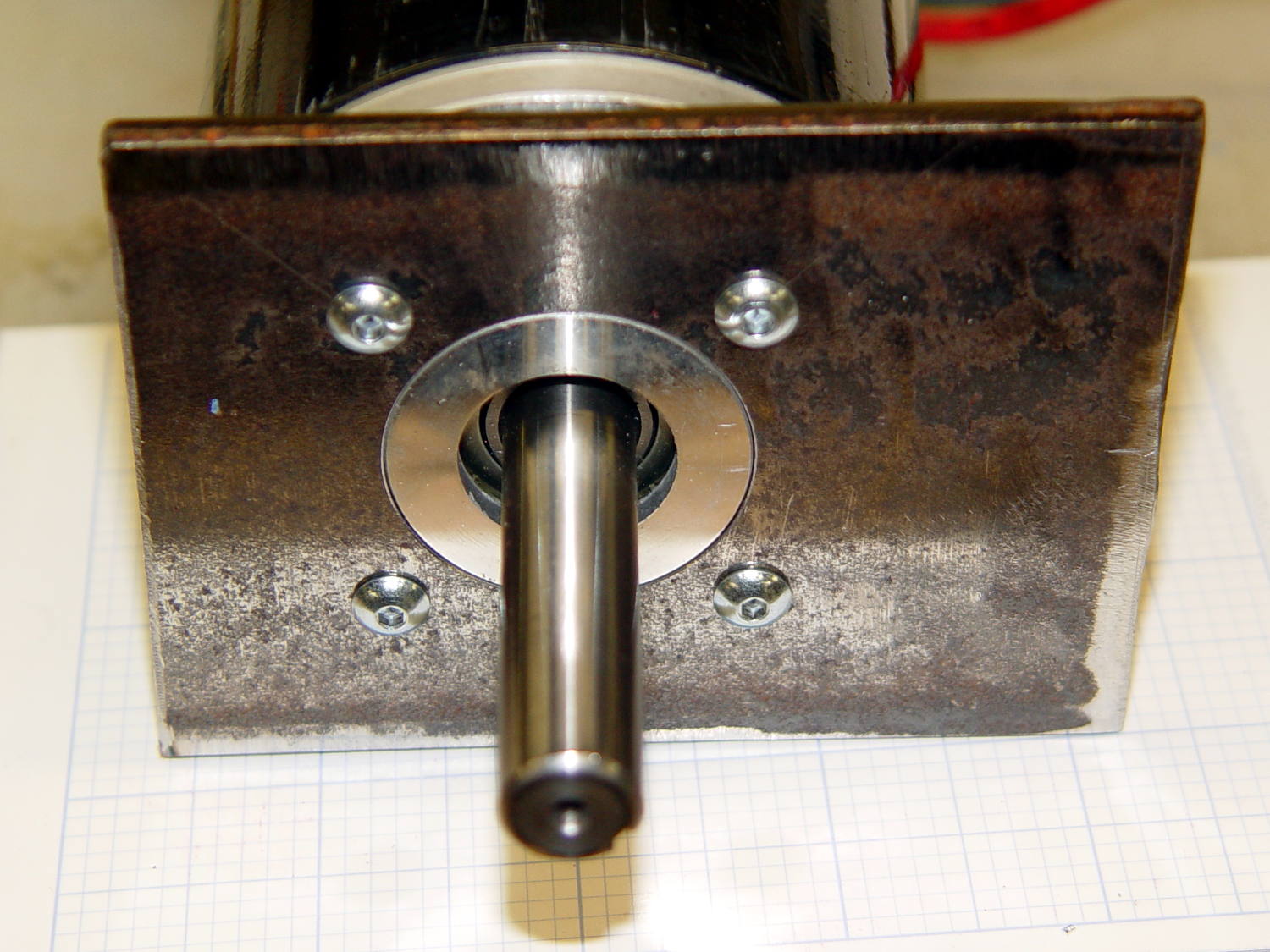
A trial fit showed the hole was slightly off-round, probably due to a few mils of backlash in both axes, and slightly too small, because that’s how I wanted it. Flipped back-to-front, reclamped, recentered, ran the cutter around at 12.75 mm to clear the ovalness, then crept out to 12.8 mm, and it was all good:
Motor Mount – test fit
That’s an easy fit with maybe 0.1 mm = 4 mil radial play around the boss. Better than that, I cannot do.
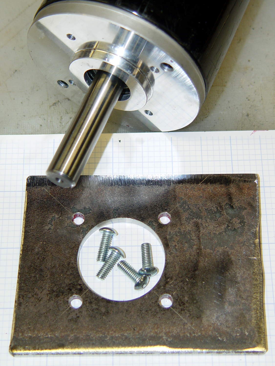
Lacquer thinner stripped the layout dye and it’s ready for welding:
Motor Mount – with motor
Reminders for next time…
The drill feed on a rigid machine with plenty of spindle power is 100 x (drill dia) @ 3000 RPM. On the Sherline, in steel, 10 x dia is optimistic. Aluminum feeds run higher, but don’t get stupid.
Re-centering to the accuracy required for this job is a matter of noting the coordinates where the cutter kisses the perimeter across a diameter along each axis, adding the coordinates, dividing by two, moving to that position, and zeroing the origin. Do that in X, Y, X, and Y and it’s good enough. You could automate that with a touch probe, of course. Hand-turning the spindle with the cutter in place to feel it kiss the workpiece is fine, but use the same cutting edge on both sides of the diameter.
Figure the chain drill diameter thusly:
Pick a reasonable drill diameter; #10 is about as large as you want on a Sherline
Drill circle dia = final milled hole diameter – drill dia – 2 mm, round down to lower integer
# holes = π x DCD / drill dia, rounded down to lower integer
Hole angle = 360 / # holes
Hole radius = DCD / 2
Wisely is it written that a man with a CNC milling machine has many friends.
The blotches on the legend in the lower left corner show that a refilled plotter pen can accumulate a droplet of ink around its nib, which should come as no surprise. I wiped off the excess immediately after refilling each pen, let the assortment sit for a few hours to (presumably) let the new ink reach the nib, and wiped them off before inserting them in the plotter’s pen carousel. All I can say is that I used up a bunch of paper towels in the process…
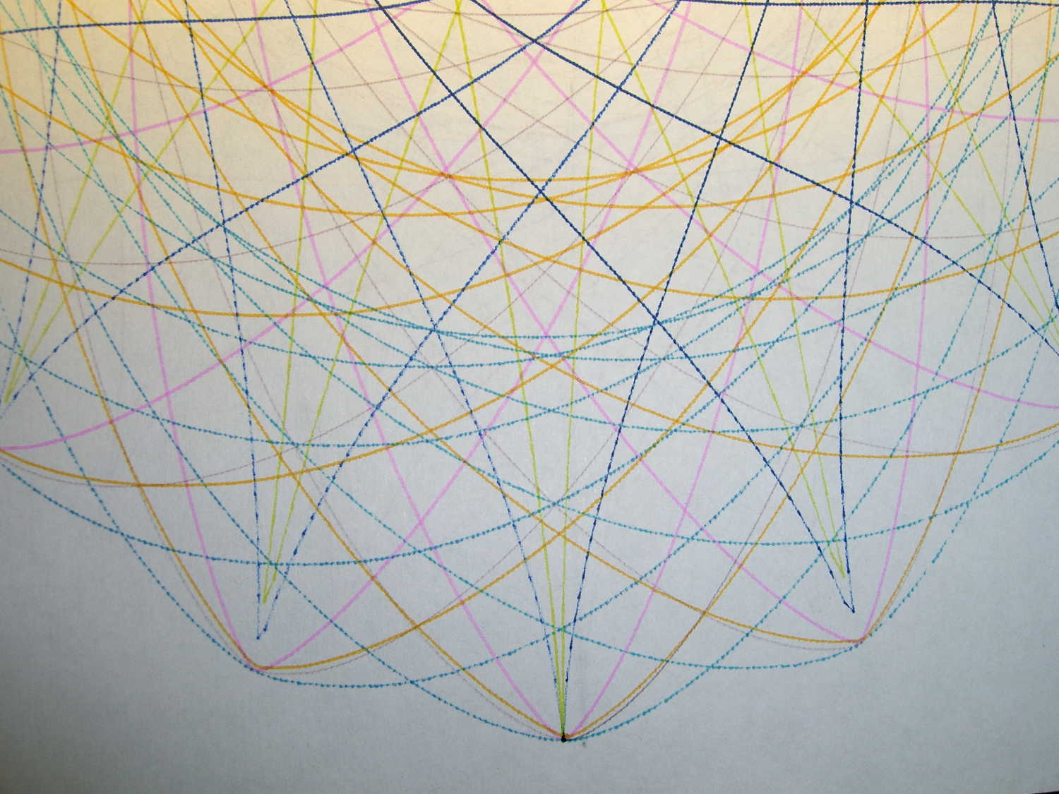
A closer look at the plot shows Pretty Good If You Ask Me results:
CMYK Refilled Pens – plot detail
The two blue-ish pens have less flow than the others, resulting in dotted lines that should be continuous. As nearly as I can tell, that’s a function of how much OEM ink has solidified in the fiber nib and, most likely, the fiber rod that draws ink from the sponge reservoir inside the body.
And, of course, the colors produced by adding CMY printer ink to the surviving OEM ink aren’t found in any catalog. I’m also blithely ignoring the difference between the inks inside plotter pens intended for paper and those for overhead transparencies; at this late date, that’s defined to Not Matter.
A place to store your vials of blended inkjet juice, plus a workstation for the plotter pen you’re refilling and that ink vial up front:
HP7475A Plotter Pen Refilling Station
The two pen holders accommodate ordinary fiber-tip pens and ceramic-tip pens. The slot along the front lets you keep track of the ink level, not that there’s much danger of running dry at 0.05 ml per refill from a vial holding 1 ml of blended ink. The big flange makes it harder for me to knock the damn thing over; avoiding an ink spill, even when you have a towel underneath, is a Good Thing.
The Slic3r tool path preview shows off the Hilbert Curve top & bottom infill:
Plotter Pen Refill Vial Holder – Slic3r preview
The OpenSCAD source code:
// HP7475A Plotter Pen Refill Station
// Ed Nisley KE4ZNU - August 2015

//- Extrusion parameters - must match reality!

ThreadThick = 0.25;
ThreadWidth = 0.40;

function IntegerMultiple(Size,Unit) = Unit * ceil(Size / Unit);

Protrusion = 0.1;

HoleWindage = 0.2;

module PolyCyl(Dia,Height,ForceSides=0) {			// based on nophead's polyholes

  Sides = (ForceSides != 0) ? ForceSides : (ceil(Dia) + 2);

  FixDia = Dia / cos(180/Sides);

  cylinder(r=(FixDia + HoleWindage)/2,
           h=Height,
	   $fn=Sides);
}


//------
// Dimensions

WallThick = 6*ThreadWidth;
BaseThick = IntegerMultiple(1.0,ThreadThick);

VialOD = 8.0;
VialOC = VialOD + WallThick;

VialArray = [4,4];			// number of vials in each direction

PenOD = [14.7,11.7];			// regular fiber pen body, ceramic *cap* dia
NumPens = len(PenOD);			// really works for just two pens...
PenLength = 38;
FlangeOD = 18;

echo(str("Max pen OD: ",max(PenOD)));
echo(str("Number of pens: ",len(PenOD)));

Holder = [(VialOC*VialArray[0] + WallThick),(VialOC*VialArray[1] + 2*FlangeOD + WallThick),(3*VialOD + BaseThick)];
HolderRound = 5.0;

//- Build it

	difference() {

		union() {
			hull() {
				for (i=[-1,1], j=[-1,1]) {
					translate([i*(Holder[0]/2 - HolderRound),j*(Holder[1]/2 - HolderRound),0])
						cylinder(r=HolderRound,h=Holder[2],$fn=8*4);
				}
			}

			hull() {
				for (i=[-1,1], j=[-1,1]) {
					translate([i*Holder[1]/2,j*(Holder[1]/2 - HolderRound),0])
						cylinder(r=HolderRound,h=BaseThick,$fn=8*4);
				}
			}

			for (i=[0:len(PenOD) - 1])
				translate([(i*Holder[0]/2 - Holder[0]/4),-Holder[1]/4,BaseThick]) {		// spacing is a total hack
					rotate(180/12)
						cylinder(d=FlangeOD,h=PenLength,$fn=3*4);
				}
		}

		for (i=[0:VialArray[0] - 1] , j=[0:VialArray[1] - 1]) {
			vx = i*VialOC - (VialOC*(VialArray[0] - 1)/2);
			vy = j*VialOC - (VialOC*(VialArray[1] - 1)/2) + FlangeOD;
			translate([vx,vy,BaseThick])
				rotate(180/8)
					PolyCyl(VialOD,Holder[2],8);
		}

		translate([0,(VialOD/2 - Holder[1]/2),BaseThick])
			rotate(180/8)
				PolyCyl(VialOD,Holder[2],8);										// edges along open side => snug fit

		for (i=[0:len(PenOD) - 1])
			translate([(i*Holder[0]/2 - Holder[0]/4),-Holder[1]/4,BaseThick]) {		// spacing is a total hack
				rotate(180/12)
					PolyCyl(PenOD[i],(PenLength + Protrusion),3*4);
			}

	}