Second time’s the charm:

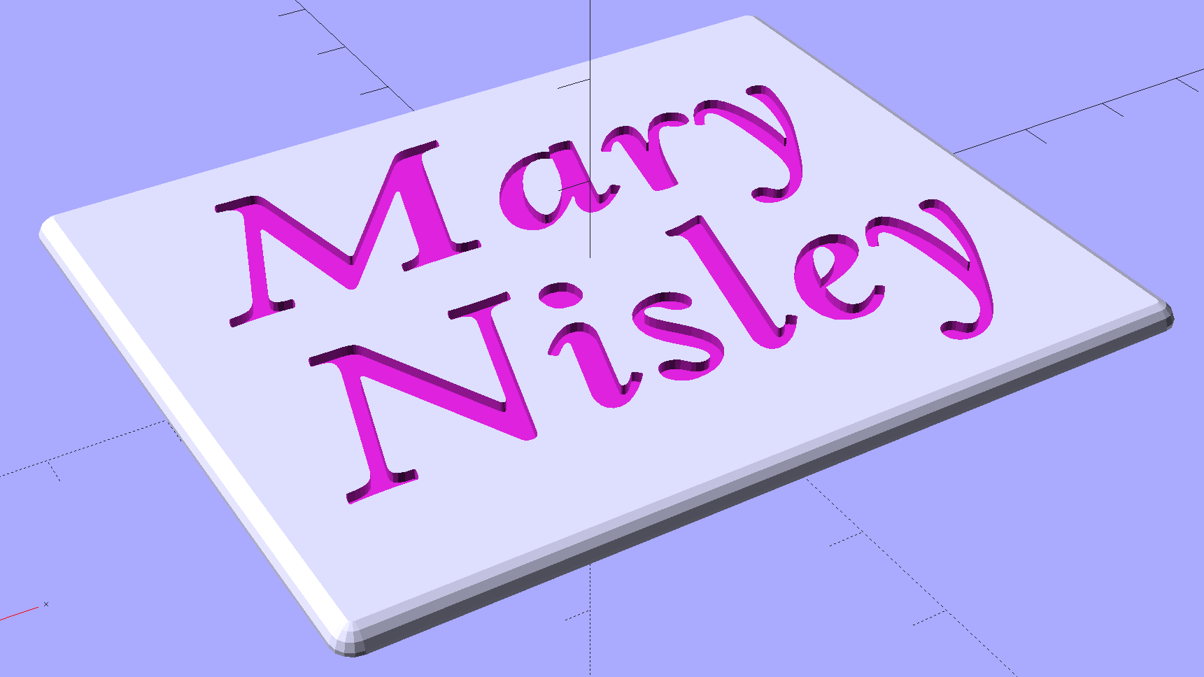
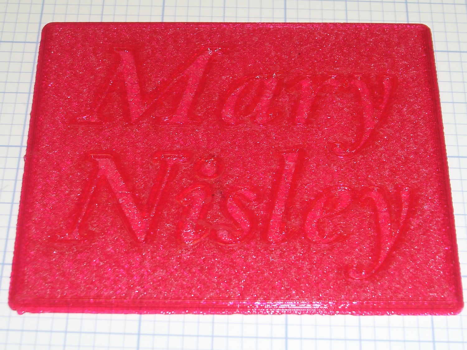
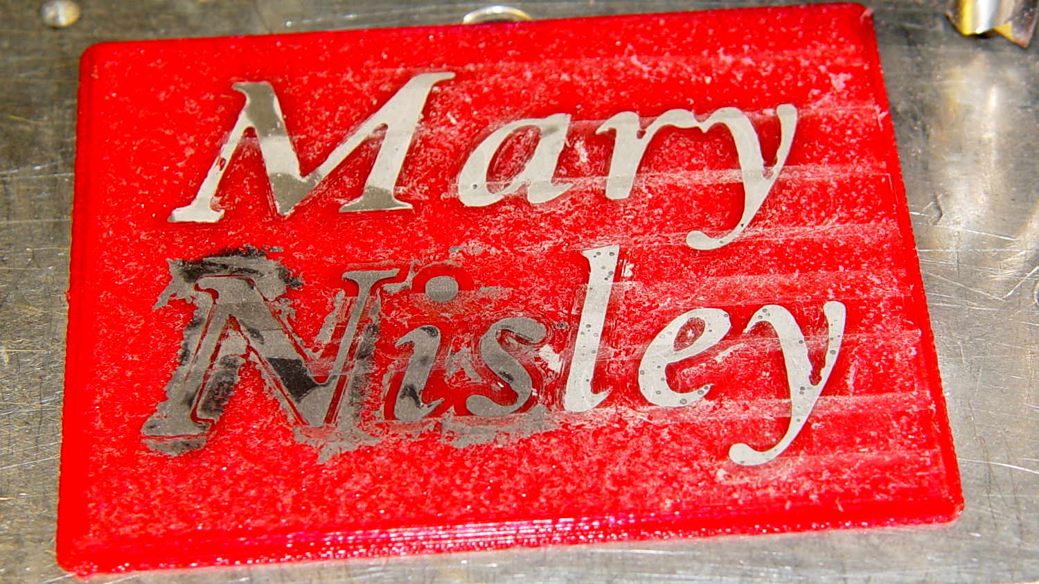
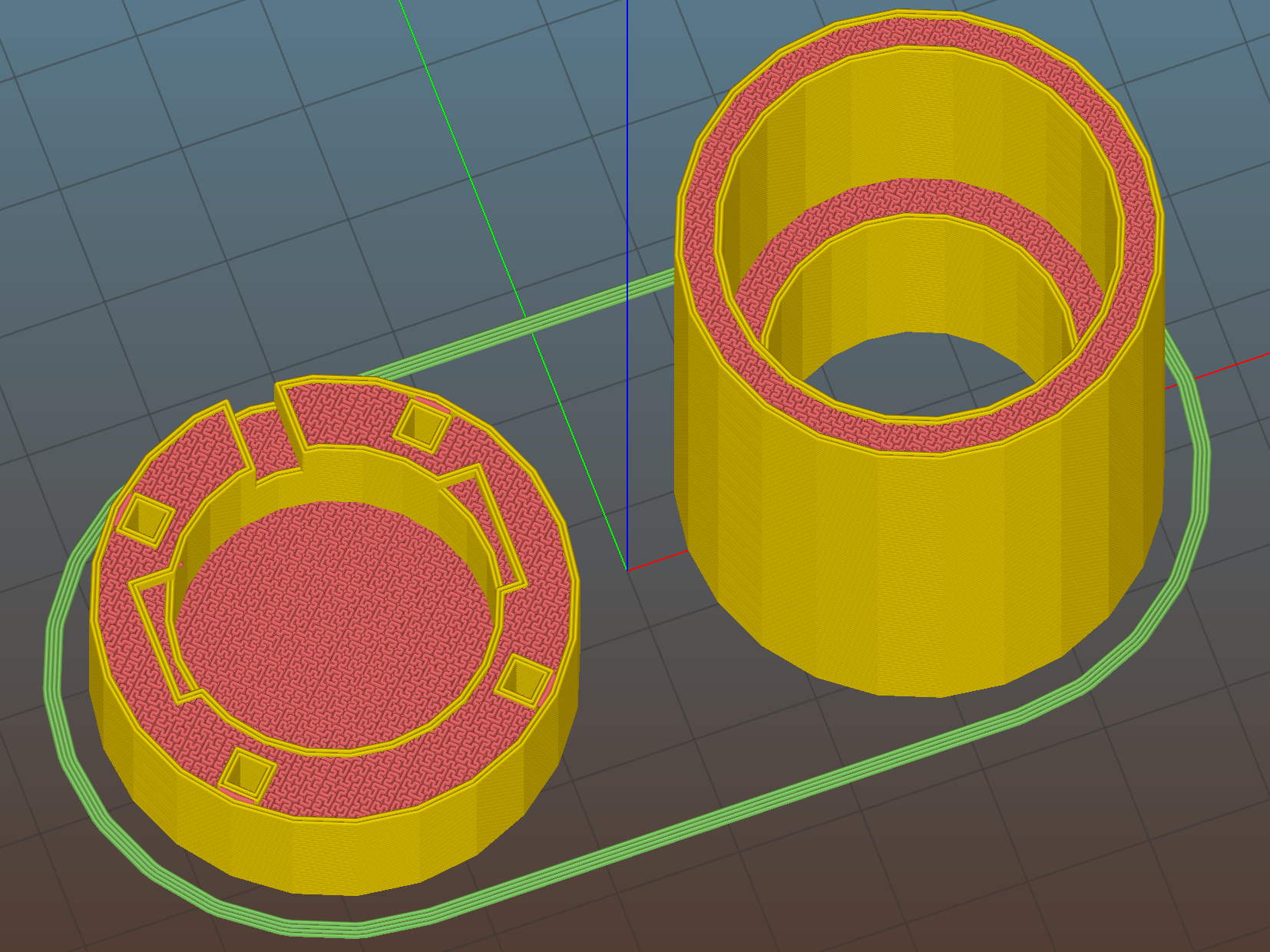
There’s not much difference from the first iteration, apart from a few code cleanups. The engraved text is kinda-sorta gratuitous, but I figured having the circuit board dimensions on all the key parts would avoid heartache & confusion; the code now autosizes the board to the holder OD. Skeletonizing the board template didn’t save nearly as much printing time as I expected, though.
Now I can build a second electrometer amp without dismantling the two-transistor version.
The OpenSCAD source code:
// Victoreen 710-104 Ionization Chamber Fittings
// Ed Nisley KE4ZNU August 2015

Layout = "Show";
					// Show - assembled parts
					// Build - print can parts + shield
					// BuildShield - print just the shield
					// BuildHolder - print just the can cap & PCB base
					// CanCap - PCB insulator for 6-32 mounting studs
					// CanBase - surrounding foot for ionization chamber
					// CanRim - generic surround for either end of chamber
					// PCB - template for cutting PCB sheet
					// PCBBase - holder for PCB atop CanCap
					// Shield - electrostatic shield shell

//- Extrusion parameters must match reality!
//  Print with 2 shells and 3 solid layers

ThreadThick = 0.25;
ThreadWidth = 0.40;

HoleWindage = 0.2;

Protrusion = 0.1;			// make holes end cleanly

AlignPinOD = 1.75;			// assembly alignment pins = filament dia

inch = 25.4;

function IntegerMultiple(Size,Unit) = Unit * ceil(Size / Unit);

//- Screw sizes

Tap4_40 = 0.089 * inch;
Clear4_40 = 0.110 * inch;
Head4_40 = 0.211 * inch;
Head4_40Thick = 0.065 * inch;
Nut4_40Dia = 0.228 * inch;
Nut4_40Thick = 0.086 * inch;
Washer4_40OD = 0.270 * inch;
Washer4_40ID = 0.123 * inch;


//----------------------
// Dimensions

OD = 0;											// name the subscripts
LENGTH = 1;

Chamber = [91.0,38];							// Victoreen ionization chamber dimensions

Stud = [										// stud welded to ionization chamber lid
	[6.5,IntegerMultiple(0.8,ThreadThick)],		// flat head -- generous clearance
	[4.0,9.5],									// 6-32 screw -- ditto
];
NumStuds = 3;									// this really isn't much of a variable...
StudAngle = 360/NumStuds;
StudSides = 6;									// for hole around stud

BCD = 2.75 * inch;								// mounting stud bolt circle diameter

PlateThick = 2.0;								// minimum layer atop and below chamber ends
RimHeight = 4.0;								// extending along chamber perimeter
WallHeight = RimHeight + PlateThick;
WallThick = 3.0;								// thick enough to be sturdy & printable
CapSides = 8*6;									// must be multiple of 4 & 3 to make symmetries work out right

RimOD = Chamber[OD] + 2*WallThick;

echo(str("Rim OD: ",RimOD));

//PCBFlatsOD = 82.0;							// desired hex dia flat-to-flat
PCBFlatsOD = floor(RimOD*cos(30)) - 2.0;		//  .. maximum possible
//PCBFlatsOD = floor(Chamber[OD]*cos(30)) - 2.0;	//  .. chamber fitting
PCBClearance = ThreadWidth;						// clearance beyond each flat for mounting

PCBThick = 1.1;
PCBActual = [PCBFlatsOD/cos(30),PCBThick];		// OD = tip-to-tip
PCBCutter = [(PCBFlatsOD + 2*PCBClearance)/cos(30),PCBThick - ThreadThick];		// OD = tip-to-tip dia + clearance

PCBSize = str(PCBFlatsOD, " mm");
echo(str("Actual PCB across flats: ",PCBFlatsOD));
echo(str(" ... tip-to-tip dia: ",PCBActual[OD]));
echo(str(" ... thickness: ",PCBActual[LENGTH]));

HolderHeight = 13.0 + PCBCutter[LENGTH];		// thick enough for PCB to clear studs + batteries
HolderShelf = 2.0;								// shelf under PCB edge
HolderTrim = 5.0;								// remove end of holder to clear PCB edge solder blobs
echo(str("Holder trim distance: ",HolderTrim));
HolderTrimAngle = StudAngle/2 - 2*atan(HolderTrim*cos(StudAngle/2)/(PCBActual[OD]/2));	// atan is close for small angles
echo(str(" ... angle: ",HolderTrimAngle));

PinAngle = 15;									// alignment pin angle on either side of holder screw

echo(str("PCB holder across flats: ",PCBCutter[OD]*cos(30)));
echo(str(" ... height: ",HolderHeight));

ShieldInset = 0.5;								// shield inset from actual PCB flat
ShieldWall = 2.0;								// wall thickness
ShieldLid = 6*ThreadThick;						// top thickness (avoid one infill layer)
Shield = [(PCBFlatsOD - 2*ShieldInset)/ cos(30),40.0];		// electrostatic shield shell dimensions

TextSize = 4;
TextCharSpace = 1.05;
TextLineSpace = TextSize + 2;
TextDepth = 1*ThreadThick;

//----------------------
// Useful routines

module PolyCyl(Dia,Height,ForceSides=0) {			// based on nophead's polyholes

  Sides = (ForceSides != 0) ? ForceSides : (ceil(Dia) + 2);

  FixDia = Dia / cos(180/Sides);

  cylinder(r=(FixDia + HoleWindage)/2,
			h=Height,
		$fn=Sides);
}

//- Locating pin hole with glue recess
//  Default length is two pin diameters on each side of the split

module LocatingPin(Dia=AlignPinOD,Len=0.0) {

	PinLen = (Len != 0.0) ? Len : (4*Dia);

	translate([0,0,-ThreadThick])
		PolyCyl((Dia + 2*ThreadWidth),2*ThreadThick,4);

	translate([0,0,-2*ThreadThick])
		PolyCyl((Dia + 1*ThreadWidth),4*ThreadThick,4);

	translate([0,0,-Len/2])
		PolyCyl(Dia,Len,4);

}

module ShowPegGrid(Space = 10.0,Size = 1.0) {

  RangeX = floor(100 / Space);
  RangeY = floor(125 / Space);

	for (x=[-RangeX:RangeX])
		for (y=[-RangeY:RangeY])
		translate([x*Space,y*Space,Size/2])
			%cube(Size,center=true);
}

//-----

module CanRim(BaseThick) {

	difference() {
		cylinder(d=Chamber[OD] + 2*WallThick,h=(WallHeight + BaseThick),$fn=CapSides);
		translate([0,0,BaseThick])
			PolyCyl(Chamber[OD],Chamber[LENGTH],CapSides);
	}

}

module CanCap() {

	difference() {
		CanRim(PlateThick + Stud[0][LENGTH]);

		translate([0,0,-Protrusion])											// central cutout
			rotate(180/6)
				cylinder(d=BCD,h=Chamber[LENGTH],$fn=6);						//  ... reasonable size

		for (i=[0:(NumStuds - 1)])												// stud clearance holes
			rotate(i*StudAngle)
				translate([BCD/2,0,0])
					rotate(180/StudSides) {
						translate([0,0,PlateThick])
							PolyCyl(Stud[0][OD],Chamber[LENGTH],StudSides);
						translate([0,0,-Protrusion])
							PolyCyl(Stud[1][OD],Chamber[LENGTH],StudSides);
					}

		for (i=[0:(NumStuds - 1)], j=[-1,1])									// PCB holder alignment pins
			rotate(i*StudAngle + j*PinAngle + 60)
				translate([Chamber[OD]/2,0,0])
					rotate(180/4 - j*PinAngle)
						LocatingPin(Len=2*(PlateThick + Stud[0][LENGTH]) - 4*ThreadThick);

		translate([-(BCD/2),0,-Protrusion])
			rotate(90) mirror()
				linear_extrude(height=(ThreadThick + Protrusion))
				text(PCBSize,size=6,font="Liberation Mono:style=bold",halign="center",valign="center");
	}

}

module CanBase() {

	difference() {
		CanRim(PlateThick);
		translate([0,0,-Protrusion])
			PolyCyl(Chamber[OD] - 2*RimHeight,Chamber[LENGTH],CapSides);
	}
}

module PCBTemplate() {

	CutLen = 10*PCBActual[LENGTH];

	difference() {
		cylinder(d=PCBActual[OD],h=PCBActual[LENGTH],$fn=6);		// actual PCB size
		translate([0,0,-Protrusion])
			cylinder(d=8,h=CutLen,$fn=12);
		if (true)
			for (i=[0:5])											// empirical cutouts
				rotate(i*60 + 30)
					translate([PCBFlatsOD/3,0,-Protrusion])
						rotate(60)
							cylinder(d=0.43*PCBActual[OD],h=CutLen,$fn=3);

		translate([PCBActual[OD]/4,0,(PCBActual[LENGTH] - ThreadThick)])
			linear_extrude(height=(ThreadThick + Protrusion),convexity=1)
			text(PCBSize,size=4,font="Liberation Mono:style=bold",halign="center",valign="center");

	}
}

module PCBBase() {

	intersection() {
		difference() {
			cylinder(d=Chamber[OD] + 2*WallThick,h=HolderHeight,$fn=CapSides);		// outer rim

			rotate(30) {
				translate([0,0,-Protrusion])										// central hex
					cylinder(d=(PCBActual[OD] - HolderShelf/cos(30) - HolderShelf/cos(30)),h=2*HolderHeight,$fn=6);

				translate([0,0,HolderHeight - PCBCutter[LENGTH]])					// hex PCB recess
					cylinder(d=PCBCutter[OD],h=HolderHeight,$fn=6);

				for (i=[0:NumStuds - 1])											// PCB retaining screws
					rotate(i*StudAngle + 180/(2*NumStuds))
						translate([(PCBCutter[OD]*cos(30)/2 + Clear4_40/2 + ThreadWidth),0,-Protrusion])
							rotate(180/6)
								PolyCyl(Tap4_40,2*HolderHeight,6);

				for (i=[0:(NumStuds - 1)], j=[-1,1])								// PCB holder alignment pins
					rotate(i*StudAngle + j*PinAngle + 180/(2*NumStuds))
						translate([Chamber[OD]/2,0,0])
							rotate(180/4 - j*PinAngle)
								LocatingPin(Len=2*(HolderHeight - 4*ThreadThick));
			}

			if (false)
			for (i=[0:NumStuds - 1])
				rotate(i*StudAngle - StudAngle/2)							// segment isolation - hex sides
					translate([0,0,-Protrusion]) {
						linear_extrude(height=2*HolderHeight)
							polygon([[0,0],[Chamber[OD],0],[Chamber[OD]*cos(180/NumStuds),Chamber[OD]*sin(180/NumStuds)]]);
					}

			translate([-(PCBFlatsOD/2 + PCBClearance - HolderShelf),0,HolderHeight/2])
				rotate([0,90,0]) rotate(90)
					linear_extrude(height=(ThreadWidth + Protrusion))
					text(PCBSize,size=6,font="Liberation Mono:style=bold",halign="center",valign="center");

		}

		for (i=[0:NumStuds - 1])
			rotate(i*StudAngle + StudAngle/2 - HolderTrimAngle/2)								// trim holder ends
				translate([0,0,-Protrusion]) {
					linear_extrude(height=2*HolderHeight)
						polygon([[0,0],[Chamber[OD],0],[Chamber[OD]*cos(HolderTrimAngle),Chamber[OD]*sin(HolderTrimAngle)]]);
				}

	}
}

//-- Electrostatic shield
//		the cutouts are completely ad-hoc

module ShieldShell() {

CutHeight = 7.0;

	difference() {
		cylinder(d=Shield[OD],h=Shield[LENGTH],$fn=6);							// exterior shape

		translate([0,0,-ShieldLid])												// interior
			cylinder(d=(Shield[OD] - 2*ShieldWall/cos(30)),h=Shield[LENGTH],$fn=6);

		translate([0,0,Shield[LENGTH] - TextDepth])
		rotate(180) {
			translate([0,0.3*Shield[OD] - 0*TextLineSpace,0])
				linear_extrude(height=(TextDepth + Protrusion))
					text("Gamma",size=TextSize,spacing=TextCharSpace,font="Liberation:style=bold",halign="center",valign="center");
			translate([0,0.3*Shield[OD] - 1*TextLineSpace,0])
				linear_extrude(height=(TextDepth + Protrusion))
					text("Ionization",size=TextSize,spacing=TextCharSpace,font="Liberation:style=bold",halign="center",valign="center");
			translate([0,0.3*Shield[OD] - 2*TextLineSpace,0])
				linear_extrude(height=(TextDepth + Protrusion))
					text("Amplifier",size=TextSize,spacing=TextCharSpace,font="Liberation:style=bold",halign="center",valign="center");
			translate([0,-0.3*Shield[OD] + 1*TextLineSpace,0])
				linear_extrude(height=(TextDepth + Protrusion))
					text("KE4ZNU",size=TextSize,spacing=TextCharSpace,font="Liberation:style=bold",halign="center",valign="center");
			translate([0,-0.3*Shield[OD] + 0*TextLineSpace,0])
				linear_extrude(height=(TextDepth + Protrusion))
					text("2015-08",size=TextSize,spacing=TextCharSpace,font="Liberation:style=bold",halign="center",valign="center");
		}

		translate([Shield[OD]/4 - 20/2,Shield[OD]/2,(CutHeight - Protrusion)/2])	// switch
			rotate(90)
				cube([Shield[OD],20,CutHeight + Protrusion],center=true);

		if (false)
		translate([-Shield[OD]/4 + 5/2,Shield[OD]/2,(CutHeight - Protrusion)/2])	// front
			rotate(90)
				cube([Shield[OD],5,CutHeight + Protrusion],center=true);

		translate([-Shield[OD]/2,0,(CutHeight - Protrusion)/2])						// right side
				cube([Shield[OD],7,CutHeight + Protrusion],center=true);

		translate([0,(Shield[OD]*cos(30)/2 - ThreadWidth),0.75*Shield[LENGTH]])
			rotate([90,0,180]) rotate(00)
				linear_extrude(height=(ThreadWidth + Protrusion))
				text(PCBSize,size=5,font="Liberation Mono:style=bold",halign="center",valign="center");
	}

}

//----------------------
// Build it

ShowPegGrid();

if (Layout == "CanRim") {
	CanRim();
}

if (Layout == "CanCap") {
	CanCap();
}

if (Layout == "CanBase") {
	CanBase();
}

if (Layout == "PCBBase") {
	PCBBase();
}

if (Layout == "PCB") {
	PCBTemplate();
}

if (Layout == "Shield") {
	ShieldShell();
}

if (Layout == "Show") {
	CanBase();
	color("Orange",0.5)
		translate([0,0,PlateThick + Protrusion])
			cylinder(d=Chamber[OD],h=Chamber[LENGTH],$fn=CapSides);
	translate([0,0,(2*PlateThick + Chamber[LENGTH] + 2*Protrusion)])
		rotate([180,0,0])
			CanCap();
	translate([0,0,(2*PlateThick + Chamber[LENGTH] + 5.0)])
		PCBBase();
	color("Green",0.5)
		translate([0,0,(2*PlateThick + Chamber[LENGTH] + 7.0 + HolderHeight)])
			rotate(30)
				PCBTemplate();
	translate([0,0,(2*PlateThick + Chamber[LENGTH] + 15.0 + HolderHeight)])
		rotate(-30)
			ShieldShell();}

if (Layout == "Build") {

	translate([-0.50*Chamber[OD],-0.60*Chamber[OD],0])
		CanCap();

	if (false)
		translate([0.55*Chamber[OD],-0.60*Chamber[OD],0])
			rotate(30)
				translate([0,0,Shield[LENGTH]])
					rotate([0,180,0])
						ShieldShell();
	if (true)
		translate([0.55*Chamber[OD],-0.60*Chamber[OD],0])
			rotate(30)
				PCBTemplate();

	if (true)
		translate([-0.25*Chamber[OD],0.60*Chamber[OD],0])
			CanBase();
		translate([0.25*Chamber[OD],0.60*Chamber[OD],0])
			PCBBase();
}

if (Layout == "BuildHolder") {
	translate([-0.25*Chamber[OD],0,0])
		CanCap();
	translate([0.25*Chamber[OD],0,0])
		PCBBase();
}

if (Layout == "BuildShield") {

	translate([0,0,Shield[LENGTH]])
		rotate([0,180,0])
				ShieldShell();


}