The Smell of Molten Projects in the Morning

Ed Nisley's Blog: Shop notes, electronics, firmware, machinery, 3D printing, laser cuttery, and curiosities. Contents: 100% human thinking, 0% AI slop.

Category: Machine Shop

Mechanical widgetry

  • Hard Drive Platter Mood Light: First Light!

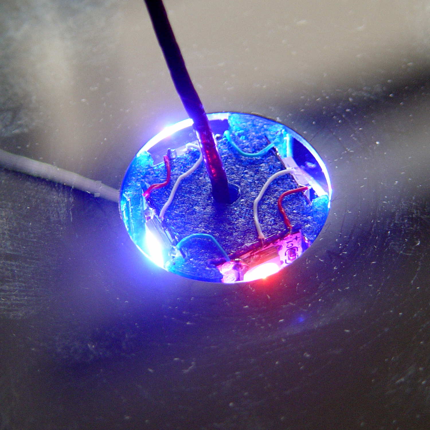
    Disassembling the (unglued!) platter stack simplified wiring the the Neopixels:

    Hard Drive Mood Light - test light
    Hard Drive Mood Light – test light

    Orienting the strips in alternate directions kept the white data connections between adjacent strips on the top and bottom level. If they sat in the same direction, the data wires would run from top to bottom.

    Each Neopixel draw 60 mA max, so each side of the pillar can draw 180 mA and lighting up all four sides in full-throttle white draws a bit over 720 mA. That’s more than those little Wire-Wrap wires should be forced to carry, but the tiny Neopixel solder pads aren’t good for much more than that. The revised column model has wiring channels behind both strip ends to provide access to the slightly larger pads on the rear surface; the fact that all the end pads get cut in half doesn’t help matters.

    The red and blue power wires connect adjacent strips, with two opposite strips wired in parallel at the bottom of the column. There’s a 100 µF cap across the incoming power leads: as much capacitor as would fit in the somewhat undersized base.

    A knockoff Arduino Pro Mini sits inline between a 5.2 VDC wall wart and the Mood Light with three connections: VCC, GND, and D6. It’s flapping around in mid-air with no protection whatsoever, so I’ll let your imagination draw that picture. I want to hide it in the base, along with a power jack, as part of the fine tuning.

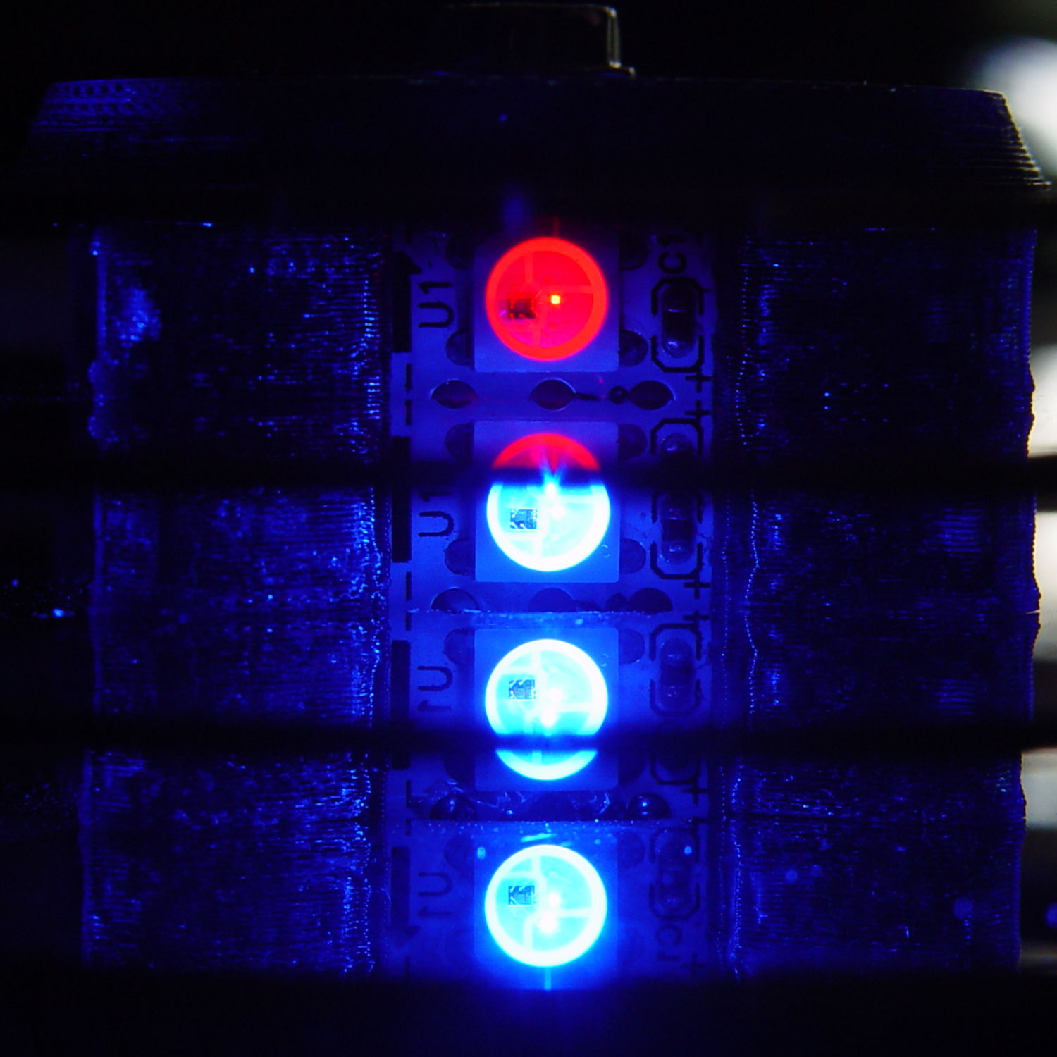
    Anyhow, restacking the platters produced this pleasant effect:

    Hard Drive Mood Light - low angle
    Hard Drive Mood Light – low angle

    You’re seeing each LEDs both directly and through a reflection in the platter below it. Despite having handled the platters for a few days, the reflection’s clarity surprised me; the multiple reflections required to bounce the LED image to the edge of the platter work perfectly:

    Hard Drive Mood Light - high angle
    Hard Drive Mood Light – high angle

    Running the original firmware (which, as noted in the comments, will eventually fall off its rails), the colors change slowly enough to be always the same while you’re watching and always different after you look away:

    Hard Drive Mood Light - red
    Hard Drive Mood Light – red

    The platters stack sufficiently parallel to each other that the LED images still have the right spacing after multiple reflections. It’s not quite an infinite house of mirrors.

    With the LEDs running at half intensity (PWM limited to 128/255), the stack lights up a dark living room just fine. At full throttle, it’d probably be too bright…

    All in all, it looks suprisingly good!

  • Hard Drive Platter Mood Light: 3D Printed Structure

    Harvesting a stack of hard drive platters and discovering that four Neopixel strips could stand vertically inside the central hole suggested this overall structure:

    Hard Drive Mood Light - solid model - Show view
    Hard Drive Mood Light – solid model – Show view

    The model includes a parameter for the number of strips, but not everything respects that. I’m not sure I’ll ever make a three-LED column and five strips won’t fit, so it probably doesn’t matter.

    The central pillar holds everything together:

    Hard Drive Mood Light - solid model - Pillar
    Hard Drive Mood Light – solid model – Pillar

    The Neopixel strips slide into those slots, which turned out to be too small to actually print, because the molten plastic pretty much squeezed the slots closed. Some deft pull saw action enlarged them enough to pass the strips, at the cost of tedious hand-fitting and considerable hidden ugliness. Printing the slots slightly larger bangs against the (lack of) printer resolution, because there’s not much wiggle room between the tiny slots and the outer diameter of the column:

    Hard Drive Mood Light - Pillar - Slic3r preview
    Hard Drive Mood Light – Pillar – Slic3r preview

    The three alignment pin holes along each edge sit 6.944 mm on center, which is what you get when you divide the nominal 1 meter strip length by 144 Neopixels. I’m using knockoff Neopixels from halfway around the planet, but they’re probably pretty close to the real thing (also from halfway around the planet, I’m sure).

    All those parts laid out on the platform, along with a fourth set of spacers in case I drop one:

    Hard Drive Mood Light - solid model - Build view
    Hard Drive Mood Light – solid model – Build view

    And they print in cyan PETG just like you’d expect:

    Hard Drive Mood Light - parts on platform
    Hard Drive Mood Light – parts on platform

    The round base (on the right) prints bottom-side-up, with bridging from the rim to the central pillar, and came out looking just fine. The top doesn’t have the central post and the pillar doesn’t have the top recess shown in the model: those tweaks will appear in the next iteration.

    Each tiny triangular spacer gets an alignment pin glued into its inner surface, then four of them get glued to the pillar. This crash test dummy pillar worked out the dimensions, so it’s squat and ugly:

    Hard Drive Platter Mood Light - pillar gluing
    Hard Drive Platter Mood Light – pillar gluing

    It’s clamped to a glass plate (smooth side up!) to force the spacers onto on a plane, with the other clamps smashing them against the pillar. All the other spacers get glued in situ atop each platter as it’s installed, which is a definite downside.

    Installing the Neopixels before assembling the platters seemed to be the right way to go:

    Hard Drive Mood Light - first platter assembly
    Hard Drive Mood Light – first platter assembly

    After that, just stack ’em up:

    Hard Drive Mood Light - top Neopixels
    Hard Drive Mood Light – top Neopixels

    I dry-assembled the upper two spacer sets, so I could pull it apart in case that seemed necessary. Turned out to be a good idea.

    And then screw the lid on top to see what it looks like:

    Hard Drive Mood Light - trial assembly
    Hard Drive Mood Light – trial assembly

    That top screw should be a pan-head or something similarly smooth, rather than a random PC case screw. The sacrificial hard drives provided a bunch of Torx screws that would surely look better; most are far too small.

    I thought a taller stack would be appropriate, but I kinda like the short, squat aspect ratio.

    Now for some wiring…

    The OpenSCAD source code:

    // Hard Drive Platter Mood Light
    // Ed Nisley KE4ZNU November 2015
    
    Layout = "Show";					// Build Show Pixel LEDString Platters Pillar Spacers TopCap Base
    
    ShowDisks = 2;						// number of disks in Show layout
    
    //- Extrusion parameters must match reality!
    
    ThreadThick = 0.20;
    ThreadWidth = 0.40;
    
    HoleWindage = 0.2;
    
    Protrusion = 0.1;			// make holes end cleanly
    
    inch = 25.4;
    
    function IntegerMultiple(Size,Unit) = Unit * ceil(Size / Unit);
    
    //----------------------
    // Dimensions
    
    ID = 0;
    OD = 1;
    LENGTH = 2;
    
    Platter = [25.0,95.0,1.27];						// hard drive platters
    
    LEDStringCount = 3;								// number of LEDs on each strip (Show mode looks odd for less than 3)
    LEDStripCount = 4;								// number of strips (verify locating pin holes & suchlike)
    
    WireSpace = 1.0;								// allowance for wiring along strip ends
    
    BaseSize = [40,14,3.0];							// overall base plate outside engine controller slot
    
    Pixel = [13.0, 1000 / 144, 0.5];				// smallest indivisible unit of LED strip
    PixelMargin = [1.0, 1.0, 2.0];					// LED and circuitry atop the strip
    
    BeamAngle = 120;								// LED viewing angle
    BeamShape = [
    	[0,0],
    	[Platter[OD]*cos(BeamAngle/2),-Platter[OD]*sin(BeamAngle/2)],
    	[Platter[OD]*cos(BeamAngle/2), Platter[OD]*sin(BeamAngle/2)]
    ];
    
    PillarSides = 12*4;
    
    PillarCore = Platter[ID] - 2*(Pixel[2] + PixelMargin[2] + 2.0);		// LED channel distance across pillar centerline
    PillarLength = LEDStringCount*Pixel[1] + Platter[LENGTH];
    echo(str("Pillar core size: ",PillarCore));
    echo(str("      ... length:"),PillarLength);
    
    Cap = [Platter[ID] + 4.0,Platter[ID] + 4.0 + 10*2*ThreadWidth,2*WireSpace + 6*ThreadThick];		// cap over top of pillar
    CapSides = 16;
    
    Base = [Platter[ID] + 10.0,0.5*Platter[OD],8.0];
    BaseSides = 16;
    
    Screw = [2.0,3.0,20.0];							// screws used to secure cap & pillar
    
    Spacer = [Platter[ID],(Platter[ID] + 2*8),(Pixel[1] - Platter[LENGTH])];
    echo(str("Spacer  OD: ",Spacer[OD]));
    echo(str(" ... thick:",Spacer[LENGTH]));
    
    LEDStripProfile = [
    	[0,0],
    	[Pixel[0]/2,0],
    	[Pixel[0]/2,Pixel[2]],
    	[(Pixel[0]/2 - PixelMargin[0]),Pixel[2]],
    	[(Pixel[0]/2 - PixelMargin[0]),(Pixel[2] + PixelMargin[2])],
    	[-(Pixel[0]/2 - PixelMargin[0]),(Pixel[2] + PixelMargin[2])],
    	[-(Pixel[0]/2 - PixelMargin[0]),Pixel[2]],
    	[-Pixel[0]/2,Pixel[2]],
    	[-Pixel[0]/2,0]
    ];
    
    //----------------------
    // Useful routines
    
    module PolyCyl(Dia,Height,ForceSides=0) {			// based on nophead's polyholes
    
      Sides = (ForceSides != 0) ? ForceSides : (ceil(Dia) + 2);
    
      FixDia = Dia / cos(180/Sides);
    
      cylinder(r=(FixDia + HoleWindage)/2,
    		h=Height,
    	$fn=Sides);
    }
    
    //- Locating pin hole with glue recess
    //  Default length is two pin diameters on each side of the split
    
    PinOD = 1.70;
    
    module LocatingPin(Dia=PinOD,Len=0.0) {
    	
    	PinLen = (Len != 0.0) ? Len : (4*Dia);
    	
    	translate([0,0,-ThreadThick])
    		PolyCyl((Dia + 2*ThreadWidth),2*ThreadThick,4);
    
    	translate([0,0,-2*ThreadThick])
    		PolyCyl((Dia + 1*ThreadWidth),4*ThreadThick,4);
    		
    	translate([0,0,-(PinLen/2 + ThreadThick)])
    		PolyCyl(Dia,(PinLen + 2*ThreadThick),4);
    
    }
    //----------------------
    // Pieces
    
    //-- LED strips
    
    module OnePixel() {
    	
    	render()
    		rotate([-90,0,0]) rotate(180)				// align result the way you'd expect from the dimensions
    			difference() {
    				linear_extrude(height=Pixel[1],convexity=3)
    					polygon(points=LEDStripProfile);
    				translate([-Pixel[0]/2,Pixel[2],-PixelMargin[0]])
    					cube([Pixel[0],2*PixelMargin[2],2*PixelMargin[0]]);
    				translate([-Pixel[0]/2,Pixel[2],Pixel[1]-PixelMargin[0]])
    					cube([Pixel[0],2*PixelMargin[2],2*PixelMargin[0]]);
    			}
    }
    
    module LEDString(n = LEDStringCount) {
    	
    	for (i=[0:n-1])
    		translate([0,i*Pixel[1]])
    //			resize([0,Pixel[1] + 2*Protrusion,0])
    				OnePixel();
    }
    
    //-- Stack of hard drive platters
    
    module Platters(n = LEDStringCount + 1) {
    	
    	color("gold",0.4)
    	for (i=[0:n-1]) {
    		translate([0,0,i*Pixel[1]])
    			difference() {
    				cylinder(d=Platter[OD],h=Platter[LENGTH],center=false,$fn=PillarSides);
    				cylinder(d=Platter[ID],h=3*Platter[LENGTH],center=true,$fn=PillarSides);
    			}
    	}
    }
    
    //-- Pillar holding the LED strips
    
    module Pillar() {
    	
    	difflen = PillarLength + 2*Protrusion;
    	
    //	render(convexity=5)
    	difference() {
    		linear_extrude(height=PillarLength,convexity=4)
    			difference() {
    				rotate(180/(12*4))
    					circle(d=Platter[ID] - 1*ThreadWidth,$fn=PillarSides);
    				
    				for (i=[0:LEDStripCount-1]) 					// clearance for LED beamwidth, may not actually cut surface
    					rotate(i*360/LEDStripCount)
    						translate([PillarCore/2,0,0])
    							polygon(points=BeamShape);
    							
    				for (i=[0:LEDStripCount-1])						// LED front clearance
    					rotate(i*360/LEDStripCount)
    						translate([(PillarCore/2 + Pixel[2]),(Pixel[0] - 2*PixelMargin[0])/2])
    							rotate(-90)
    								square([Pixel[0] - 2*PixelMargin[0],Platter[ID]]);
    
    			}
    			
    		for (i=[0:LEDStripCount-1])								// LED strip slots
    			rotate(i*360/LEDStripCount)
    				translate([PillarCore/2,0,-Protrusion])
    					linear_extrude(height=difflen,convexity=2)
    						rotate(-90)
    							polygon(points=LEDStripProfile);
    		
    		for (i=[0,90])											// wiring recess on top surface
    			rotate(i)
    				translate([0,0,(PillarLength - (WireSpace/2 - Protrusion))])
    					cube([(PillarCore + 2*Protrusion),Pixel[0] - 2*PixelMargin[0],WireSpace],center=true);
    							
    		for (i=[0:LEDStripCount-1])								// wiring recess on bottom surface
    			rotate(i*90)
    				translate([PillarCore/2 - (WireSpace - Protrusion)/2,0,WireSpace/2 - Protrusion])
    					cube([WireSpace + Protrusion,Pixel[0] - 2*PixelMargin[0],WireSpace],center=true);
    							
    		for (j=[0:LEDStringCount-1])							// platter spacer alignment pins
    			for (i=[0:LEDStripCount-1])
    				rotate(i*360/LEDStripCount + 180/LEDStripCount)
    					translate([(Platter[ID] - 1*ThreadWidth)/2,0,(j*Pixel[1] + Pixel[1]/2 + Platter[LENGTH]/2)])
    						rotate([0,90,0])
    							rotate(45)
    								LocatingPin();
    								
    		translate([0,0,-Protrusion])							// central screw hole
    			rotate(180/4)
    				PolyCyl(Screw[ID],difflen,4);
    		
    		if (false)
    		for (i=[-1,1])											// vertical wire channels
    			rotate(i*360/LEDStripCount + 180/LEDStripCount)
    				translate([PillarCore/2 - 2.0,0,-Protrusion])
    					PolyCyl(2.0,difflen,4);
    					
    		for (i=[-1,1])											// locating pins
    			rotate(i*360/LEDStripCount - 180/LEDStripCount)
    				translate([PillarCore/2 - 2.0,0,0])
    					LocatingPin();
    	}
    }
    
    //-- Spacers to separate platters
    
    module Spacers() {
    
    	difference() {
    		linear_extrude(height=Spacer[LENGTH],convexity=4)
    			difference() {
    				rotate(180/PillarSides)
    					circle(d=Spacer[OD],$fn=PillarSides);
    				
    				for (i=[0:LEDStripCount-1]) 					// clearance for LED beamwidth, may not actually cut surface
    					rotate(i*360/LEDStripCount)
    						translate([PillarCore/2,0,0])
    							polygon(points=BeamShape);
    							
    				for (i=[0:LEDStripCount-1])						// LED front clearance
    					rotate(i*360/LEDStripCount)
    						translate([(PillarCore/2 + Pixel[2]),(Pixel[0] - 2*PixelMargin[0])/2])
    							rotate(-90)
    								square([Pixel[0] - 2*PixelMargin[0],Platter[ID]]);
    
    							
    				rotate(180/PillarSides)
    					circle(d=Spacer[ID],$fn=PillarSides);		// central pillar fits in the hole
    			}
    			
    		for (i=[0:LEDStripCount-1])
    			rotate(i*360/LEDStripCount + 180/LEDStripCount)
    				translate([Platter[ID]/2,0,(Pixel[1] - Platter[LENGTH])/2])
    					rotate([0,90,0])
    						rotate(45)
    							LocatingPin();
    
    	}
    }
    
    //-- Cap over top of pillar
    
    module TopCap() {
    	
    	difference() {
    		cylinder(d1=(Cap[OD] + Cap[ID])/2,d2=Cap[OD],h=Cap[LENGTH],$fn=CapSides);		// outer lid
    		
    		translate([0,0,-Protrusion])
    			PolyCyl(Screw[ID],Cap[LENGTH] + WireSpace + Protrusion,4);					// screw hole
    		
    		translate([0,0,Cap[LENGTH] - 2*WireSpace])
    			difference() {
    				cylinder(d=Cap[ID],h=2*Cap[LENGTH],$fn=CapSides);						// cutout
    				cylinder(d=2*Screw[OD],h=Cap[LENGTH],$fn=CapSides);						// boss
    			}
    		
    		translate([0,0,Cap[LENGTH] - ThreadThick])
    			cylinder(d=Cap[ID]/2,h=ThreadThick + Protrusion,$fn=CapSides);				// recess boss
    	}
    }
    
    //-- Base below pillar
    
    module Base() {
    	
    	SideWidth = 0.5*Base[OD]*sin(180/BaseSides);						// close enough
    	
    	difference() {
    		union() {
    			difference() {
    				cylinder(d=Base[OD],h=Base[LENGTH],$fn=BaseSides);			// outer base
    
    				translate([0,0,6*ThreadThick])								// main cutout
    					cylinder(d=Base[ID],h=Base[LENGTH],$fn=BaseSides);
    					
    				translate([-SideWidth/2,0,6*ThreadThick]) 					// cable port
    					cube([SideWidth,Base[OD],Base[LENGTH]]);
    			}
    			
    			translate([0,0,Base[LENGTH]/2])									// pillar support is recessed below rim
    				cube([PillarCore,PillarCore,Base[LENGTH] - ThreadThick],center=true);
    		}
    
    		for (i=[0:LEDStripCount-1])											// wiring recesses
    			rotate(i*90)
    				translate([PillarCore/2 - (WireSpace - Protrusion)/2,0,Base[LENGTH] - WireSpace/2])
    					cube([WireSpace + Protrusion,PillarCore - 4*WireSpace,WireSpace],center=true);
    		
    		translate([0,0,-Protrusion])
    			PolyCyl(Screw[ID],2*Base[LENGTH],4);						// screw hole
    			
    		translate([0,0,-Protrusion])									// screw head recess
    			PolyCyl(8.5,5.0 + Protrusion,$fn=6);
    			
    		for (i=[-1,1])													// locating pins
    			rotate(i*360/LEDStripCount - 180/LEDStripCount)
    				translate([PillarCore/2 - 2.0,0,Base[LENGTH] - ThreadThick])
    					LocatingPin();
    
    	}
    		
    }
    
    //----------------------
    // Build it
    
    if (Layout == "Pixel")
    	OnePixel();
    	
    if (Layout == "LEDString")
    	LEDString(LEDStringCount);
    	
    if (Layout == "Platters")
    	Platters(LEDStringCount + 1);
    	
    if (Layout == "Pillar")
    	Pillar(LEDStringCount);
    	
    if (Layout == "TopCap")
    	TopCap();
    		
    if (Layout == "Base")
    	Base();
    
    if (Layout == "Spacers")
    	Spacers();
    	
    if (Layout == "Show") {
    	Pillar();
    
    	for (i=[0:LEDStripCount-1])											// LED strips
    		rotate(i*360/LEDStripCount)
    			translate([PillarCore/2,0,Platter[LENGTH]/2])
    				rotate([90,0,90])
    					color("lightblue") LEDString();
    	if (true)	
    	for (j=[0:max(1,ShowDisks - 2)])									// spacers
    		translate([0,0,(j*Pixel[1] + Platter[LENGTH])])
    			color("cyan") Spacers();
    							
    	for (j=[0:max(2,ShowDisks - 2)])										// spacer alignment pins
    		for (i=[0:LEDStripCount-1])
    			rotate(i*360/LEDStripCount + 180/LEDStripCount)
    				translate([(Platter[ID] - 1*ThreadWidth)/2,0,(j*Pixel[1] + Pixel[1]/2 + Platter[LENGTH]/2)])
    					rotate([0,90,0])
    						rotate(45)
    							 color("Yellow",0.25) LocatingPin(Len=4);
    	translate([0,0,PillarLength + 3*Cap[LENGTH]])
    		rotate([180,0,0])
    			TopCap();
    	
    	translate([0,0,-3*Base[LENGTH]])
    		Base();
    		
    	if (ShowDisks > 0)	
    		Platters(ShowDisks);
    	
    }
    
    // Ad-hoc build layout
    
    if (Layout == "Build") {
    	Pillar();
    	
    	translate([0,Cap[OD],0])
    		TopCap();
    	
    	translate([0,-Base[OD],Base[LENGTH]])
    		rotate([0,180,0])
    			Base();
    	
    	Ybase = Spacer[OD] * (LEDStringCount%2 ? (LEDStringCount - 1) : (LEDStringCount - 2)) / 4;
    	for (i=[0:LEDStringCount])										// build one extra set of spacers!
    		translate([(i%2 ? 1 : -1)*(Spacer[OD] + Base[OD])/2,		// alternate X sides to shrink Y space
    				   (i%2 ? i-1 : i)*Spacer[OD]/2 - Ybase,			// same Y for even-odd pairs in X
    				   0])
    			Spacers();
    }
    

    The original doodles showing this might work, along with some ideas that wouldn’t:

    Hard Drive Mood Light - Doodles 1
    Hard Drive Mood Light – Doodles 1
    Hard Drive Mood Light - Doodles 2
    Hard Drive Mood Light – Doodles 2
    Hard Drive Mood Light - Doodles 3
    Hard Drive Mood Light – Doodles 3
  • Poughkeepsie Day School Mini MakerFaire

    In the (admittedly unlikely) event you’re in the neighborhood today, visit the Poughkeepsie Mini MakerFaire. I’ll be doing a “Practical 3D Printing” show-n-tell in one of the tiny music practice rooms in the main hallway, handing out tchochkes, and generally talking myself hoarse. The HP 7475A plotter will be cranking out Superforumulas next door, too, because everybody loves watching a plotter.

    Usually, I print dump trucks or some such, but yesterday I hammered out the models for two adapters that mate the new vacuum cleaner to some old tools, so I’ll be doing live-fire production printing. I’m sure you can get adapters on Amazon, but what’s the fun in that?

    The magic wand that sucks dust off the evaporator coils under the refrigerator slides into the bottom end of this one:

    Refrigerator Coil Wand Adapter
    Refrigerator Coil Wand Adapter

    And the snout of this slides into the tiny floor brush that fits into spots the new one can’t reach:

    Floor Brush Adapter
    Floor Brush Adapter

    And, with a Faire wind in my sails, perhaps I can run off the bits required for a hard drive mood light:

    Hard Drive Mood Light - solid model - Show view
    Hard Drive Mood Light – solid model – Show view

    More details on all those later…

  • 3D Printer Nozzle-to-Platform Gap Visualization

    Here’s what the 0.35 mm diameter nozzle of my Makergear M2 looks like when printing a 0.40×0.25 mm thread on borosilicate glass with a coating of hairspray:

    M2 V4 nozzle - thinwall box first layer
    M2 V4 nozzle – thinwall box first layer

    The dimensions:

    Extrusion Dimensions
    Extrusion Dimensions

    Some common household objects at the same scale:

    Objects vs Thread Comparison
    Objects vs Thread Comparison

    The accuracy required is literally hair-fine: being off by the diameter of the hair on your head can wreck the first layer of the printed object.

    One turn of the M3 screws supporting the M2 platform move the mounting point by twice the thread thickness. Their positions on the platform amplify the motion by about a factor of two, so if you’re tweaking the screws by more than 1/6 turn at a time, you’re overdoing it.

    For first-layer nozzle-to-platform distance adjustment:

    • If it increases by 0.25 mm, the plastic won’t touch the platform
    • If it decreases by 0.25 mm, the plastic won’t come out of the nozzle

    For platform alignment:

    • If your printer can’t maintain the proper gap to within ±0.10 mm across the entire platform, it won’t produce accurate results
    • Platform alignment that looks good probably isn’t

    After you do a coarse alignment and set the Extrusion Multiplier to get accurate thread width, print thinwall hollow boxes and use your trusty digital calipers to make the platform settings & adjustments perfect.

    Works for me, anyhow. All I do is slice whatever object I’ve just designed, turn the M2 on, and print it. No muss, no fuss, no wasted motion: It Just Works.

    The sketches come from my Digital Machinist column (DM 10.4). They’ve been covering a bunch of 3D printing topics, so if you’re interested in that kind of stuff…

  • Tecumseh 36638 Throttle Knob

    The upper-left tab broke off this “knob” shortly after we got the leaf shredder:

    Throttle knob - broken original
    Throttle knob – broken original

    But it worked well enough that, following my usual course of action, I could ignore the problem. Until a few days ago, that is, when the remaining tab on that end pulled out of the slot on the engine and the whole affair bent into uselessness.

    It’s a $10 item from eBay (with free shipping), $8 from Amazon ($4, not eligible for Prime, so plus $4 shipping), out of stock at my usual online small engine source, and not worth biking a few dozen miles here & there to see if anybody has one. I know better than to look for repair parts at Lowe’s / Home Depot. It’s Tecumseh Part 36638, which may come in handy some day.

    So, we begin…

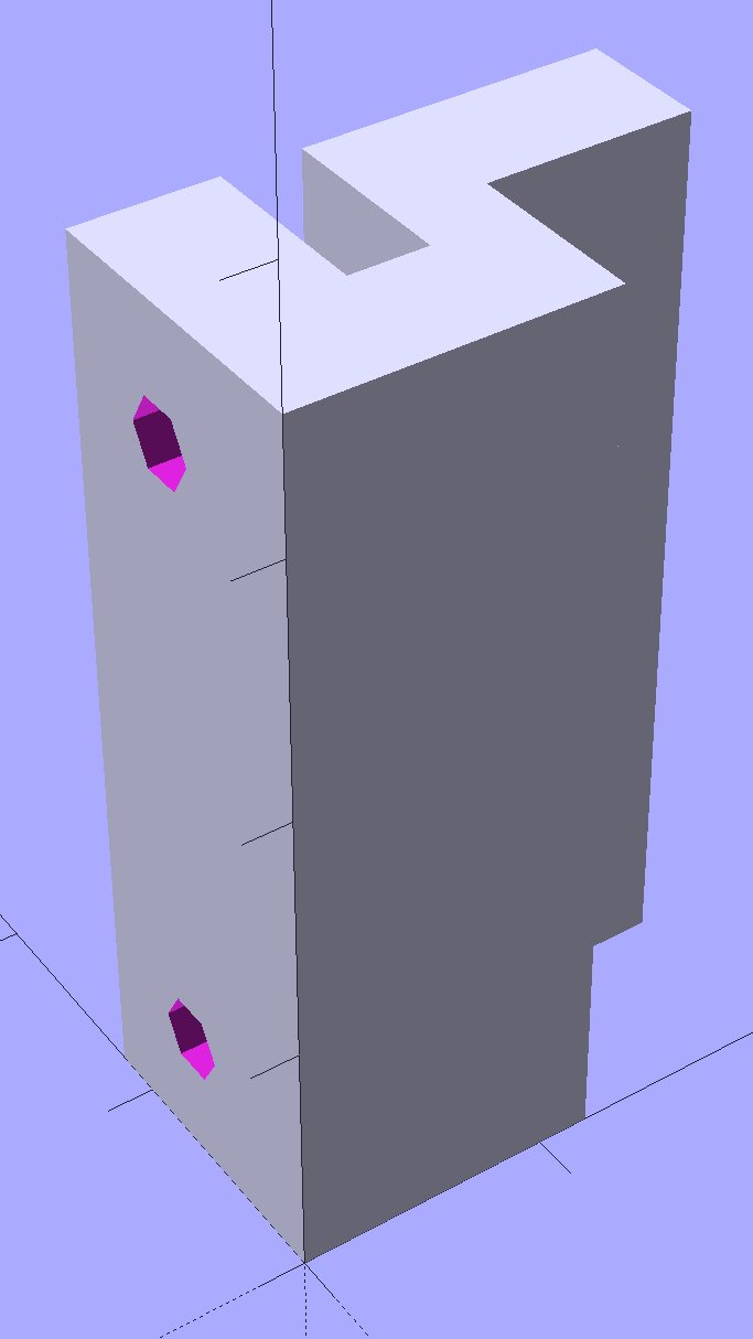
    It’s one of those pesky injection-molded miracle plastic doodads that can’t be printed in one piece, so I designed the tabs as separate parts and glued them in place. The solid model shows the intended assembly, with a bit of clearance around the tabs for tolerance and glue slop:

    Tecumseh Throttle Knob - solid model - show view
    Tecumseh Throttle Knob – solid model – show view

    External clearances aren’t an issue, so I made the base plate longer, wider, and thicker, which gave the tabs something to grab onto. The half-round knob is bigger, more angular, and uglier than the OEM knob, because I had trouble holding onto the original while wearing work gloves.

    Printing a few extra tabs allows the inevitable finger fumble:

    Throttle knob - on platform
    Throttle knob – on platform

    The tabs stand on edge to properly orient the printed threads around the perimeter: a great force will try to rip that triangular feature right off the tab, so wrapping the thread as shown maximizes the strength. Laying them flat on their backs would put the force in shear, exactly parallel to thread-to-thread bonds; I wouldn’t bet on the strength of those layers.

    The brim provides enough platform footprint around the tabs to keep them upright, but obviously isn’t needed around the knob. Although you could wrap a modifier mesh around one or the other, trimming the brim off the knob with a precision scissors seemed more straightforward.

    Slobbering generous drops of of IPS #4 solvent adhesive into the slots and over the tabs softened the PETG enough that I could ram the tabs into place, using a big pliers to overcome their feeble resistance:

    Throttle knob - glued latches
    Throttle knob – glued latches

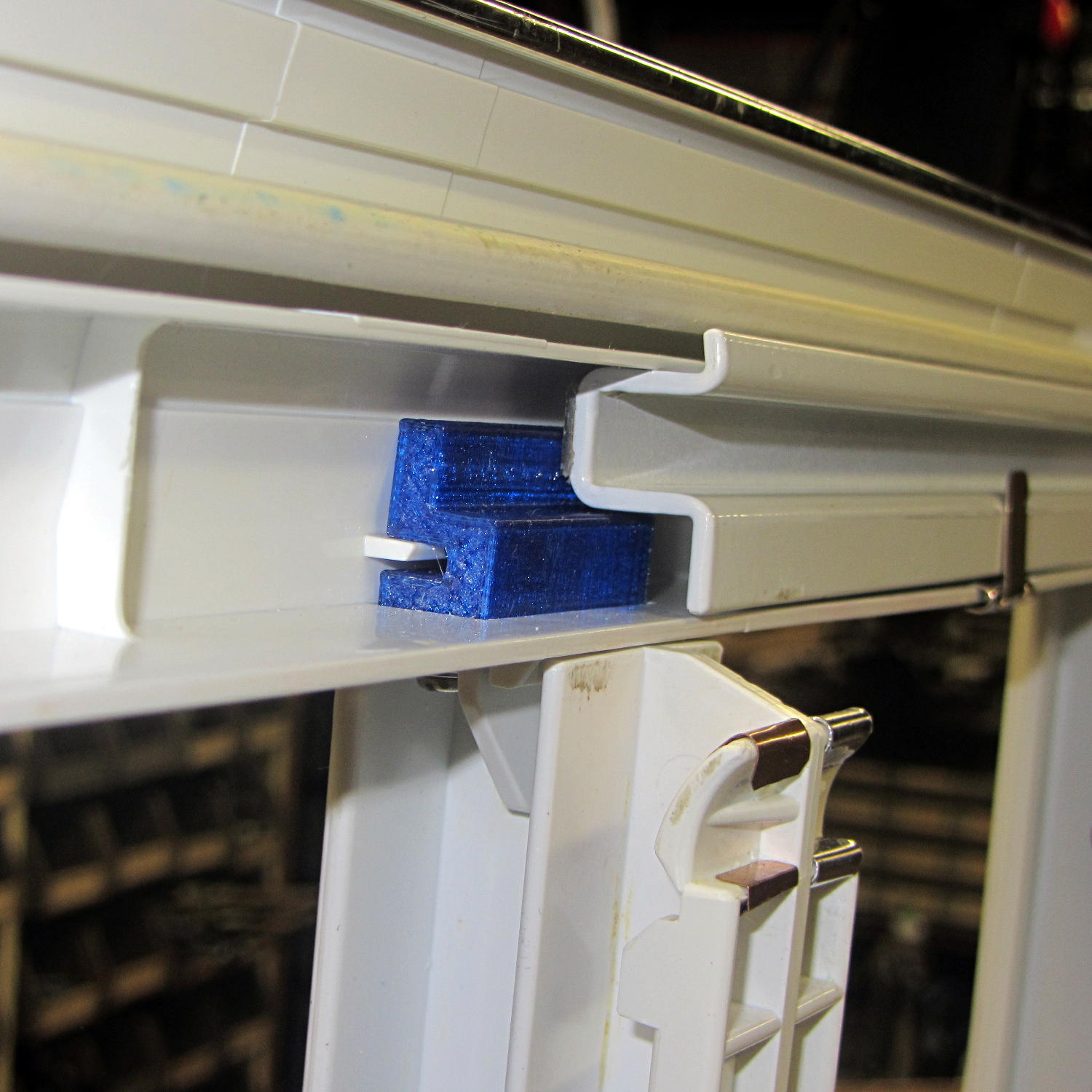
    With the plastic still dazed from the fumes, I force-fit the knob into the slot on the engine:

    Throttle knob - installed
    Throttle knob – installed

    The tabs eased back into position and seem to be holding the knob in place. Worst case: make a new knob, butter up the tabs with slow epoxy, ram knob into slot, then poke a screwdriver inside to realign the tabs against the slot edges.

    The solvent had a few cloudy days to evaporate before the next shredding session, whereupon the throttle once again worked exactly the way it should.

    The OpenSCAD source code:

    // Tecumseh 36638 Throttle Knob
    // Ed Nisley KE4ZNU November 2015
    
    Layout = "Build";					// Build Show Tab Base
    
    //- Extrusion parameters must match reality!
    
    ThreadThick = 0.25;
    ThreadWidth = 0.40;
    
    HoleWindage = 0.2;
    
    Protrusion = 0.1;			// make holes end cleanly
    
    inch = 25.4;
    
    function IntegerMultiple(Size,Unit) = Unit * ceil(Size / Unit);
    
    //----------------------
    // Dimensions
    
    BaseSize = [40,14,3.0];							// overall base plate outside engine controller slot
    
    Knob = [18,BaseSize[1],17];
    
    TabSize = [7.5,1.6,6.0];						// ovarall length, minimum width, overall height
    TabSocket = [8.0,2.0,BaseSize[2] - 2*ThreadThick];				// recess in base plate for tab 
    
    TabOuterSpace = 30.0;							// end-to-end length over tabs - sets travel distance
    SlotWidth = 7.75;								// engine controller slot width
    SlotThick = 1.5;								// engine controller slot thickness
    
    TabShape = [
    	[0,0],
    	[BaseSize[2] + TabSize[2],0],
    	[BaseSize[2] + TabSize[2],ThreadWidth],
    	[BaseSize[2] + SlotThick,2*TabSize[1]],
    	[BaseSize[2] + SlotThick,TabSize[1]],
    	[0,TabSize[1]]
    ];
    
    CapBaseOpening = [11,7.5,15];			// opening in base plate, Z = clearance from controller plate
    
    //----------------------
    // Useful routines
    
    module PolyCyl(Dia,Height,ForceSides=0) {			// based on nophead's polyholes
    
      Sides = (ForceSides != 0) ? ForceSides : (ceil(Dia) + 2);
    
      FixDia = Dia / cos(180/Sides);
    
      cylinder(r=(FixDia + HoleWindage)/2,
    		h=Height,
    	$fn=Sides);
    }
    
    //----------------------
    // Pieces
    
    module Tab() {
    	
    	linear_extrude(height=TabSize[0]) {
    		polygon(points=TabShape);
    	}
    }
    
    
    module Base() {
    	
    	CornerRad = BaseSize[1]/8;
    
    	difference() {
    		union() {
    			linear_extrude(height=BaseSize[2])
    				hull()
    					for (i=[-1,1], j=[-1,1]) 
    						translate([i*(BaseSize[0]/2- CornerRad),j*(BaseSize[1]/2 - CornerRad)])
    							circle(r=CornerRad,$fn=4*4);
    			translate([Knob[0]/2,0,BaseSize[2] - Protrusion])
    				rotate([0,-90,0])
    					linear_extrude(height=Knob[0])
    						hull() {
    							translate([Knob[2] - Knob[1]/2,0])
    								circle(d=Knob[1],$fn=8*4);
    							translate([0,-Knob[1]/2,0])
    								square([Protrusion,Knob[1]]);
    						}
    		}
    		
    		translate([-CapBaseOpening[0]/2,-CapBaseOpening[1]/2,-Protrusion])
    			cube(CapBaseOpening + [0,0,-CapBaseOpening[1]/2 + Protrusion],center=false);
    			
    		translate([0,0,CapBaseOpening[2] - CapBaseOpening[1]/2])
    			rotate([0,90,0]) rotate(180/8)
    				cylinder(d=CapBaseOpening[1]/cos(180/8),h=CapBaseOpening[0],center=true,$fn=8);
    				
    		for (i=[-1,1], j=[-1,1])
    			translate([i*(TabOuterSpace/2 - TabSocket[0]/2),j*(SlotWidth/2 - TabSocket[1]/2),TabSocket[2]/2 - Protrusion])
    				cube(TabSocket + [0,0,Protrusion],center=true);
    	}
    }
    
    
    //----------------------
    // Build it
    
    if (Layout == "Base")
    	Base();
    	
    if (Layout == "Tab")
    	Tab();
    	
    if (Layout == "Show") {
    	Base();
    	
    		for (i=[-1,1], j=[-1,1])
    			translate([i*(TabOuterSpace/2 - TabSocket[0]/2),j*(SlotWidth/2 - TabSocket[1]/2),0])
    				translate([j < 0 ? TabSize[0]/2 : -TabSize[0]/2,j < 0 ? TabSize[1]/2 : -TabSize[1]/2,BaseSize[2] - 2*ThreadThick])
    					rotate([0,90,j < 0 ? -180 : 0])
    					Tab();
    }
    
    if (Layout == "Build") {
    	Base();
    	
    	for (i=[0:5])					// build a few spares
    		translate([-7*TabSocket[1] + i*3*TabSocket[1],BaseSize[1],0])
    			rotate(90)
    				Tab();
    }
    

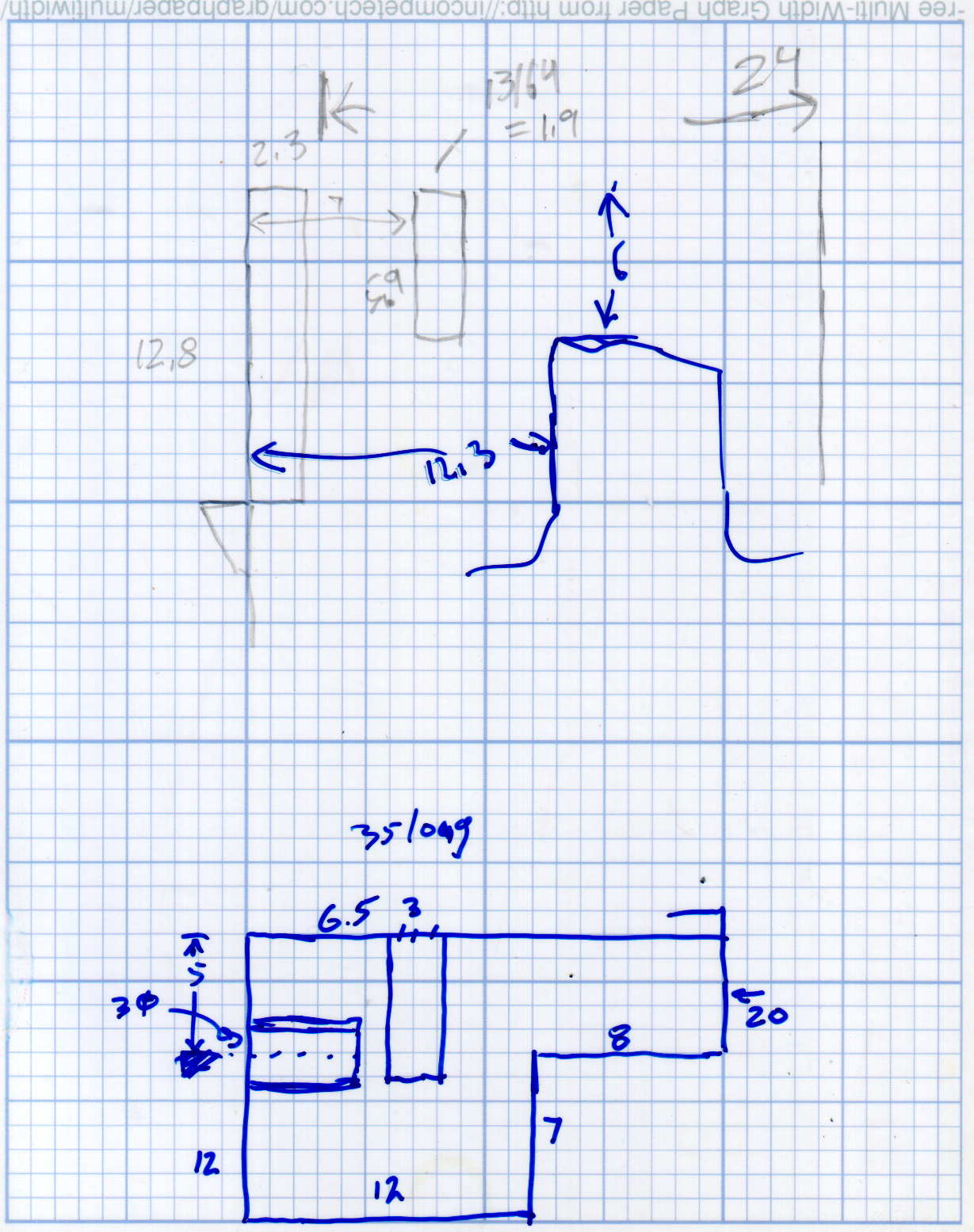
    The original doodle showing the OEM knob dimensions and some failed attempts at fancy features:

    Tecumseh Throttle Knob - doodles
    Tecumseh Throttle Knob – doodles
  • Tiny Cylinder Test Object

    A discussion on the M2 forums prompted this test object:

    Tiny Cylinder - 0.9x9.0 mm
    Tiny Cylinder – 0.9×9.0 mm

    Sliced with Slic3r for PETG at 1 mm/s, with fans in full effect. It sits amid a 5 mm brim, inside a skirt that uses 15 mm of filament, giving it a Washington Monument aspect.

    The challenge was to print a 0.7x9.0 cylinder, which doesn’t work well with a 0.35 mm nozzle. Instead, I went with 0.9 mm diameter. The result measures 1.1 mm over all the obvious bumps, so it’s surprisingly close. The “nail head” at the bottom most likely comes from the hot end depressurizing as it suddenly transitions from 15 mm/s in the brim to 1 mm/s for the cylinder.

    Fairly obviously, you can’t print something like that at full speed (50 mm/s was claimed for a Rep 2 and I don’t believe that for an instant). Indeed, it’s such a pathological model that Slic3r’s minimum layer time and small perimeter settings had no effect; I had to manually set the extrusion speed to 1 mm/s in order to make it work. Plus adding that brim, because I knew it wouldn’t stand by itself.

    Other than that, printing it was no big deal.

    A picture from that M2 forum discussion suggests you can go crazy with this stuff:

    20 mm, 40 mm, 60 mm and 120 mm
    20 mm, 40 mm, 60 mm and 120 mm

    The OpenSCAD source code for my version:

    cylinder(d=0.9,h=9,$fn=8);
    

    There, now, that wasn’t so hard, was it?

  • Sony and Wasabi NP-BX1 Li-Ion Battery Life

    Using the Sony HDR-AS30V helmet camera more-or-less daily during the bicycling season chews up batteries as well as MicroSD cards:

    Sony NP-BX1 - OEM Wasabi - 2015-10-25
    Sony NP-BX1 – OEM Wasabi – 2015-10-25

    The dotted traces show the most recent status and the solid traces are from almost exactly one year ago:

    • Red = Genuine Sony
    • Blue = Wasabi Power: cell D, August 2014
    • Green = Wasabi Power: cell B, January 2014

    All the tests are at 500 mA, approximately half the camera’s load. Oddly, the numeric values along the mA·h axis work out pretty close to the actual runtime in hours:

    • Sony – 1:30
    • Wasabi D – 1:15
    • Wasabi B – 0:40

    Given that a typical bike ride takes an hour, the two year old Wasabi B battery’s 40 minute runtime isn’t useful. The Wasabi D battery is a bit over a year old and looks very much like the B battery did last year.

    The Wasabi batteries march through the camera and charger in order, so each one gets used about once a week. The Sony battery gets used once every half-dozen complete cycles, just so I have a standard “good” battery.

    The Sony and Wasabi B cells over the course of two years:

    Sony NP-BX1 - OEM Wasabi - 2015-10 2014-10 2014-01
    Sony NP-BX1 – OEM Wasabi – 2015-10 2014-10 2014-01

    Much to my surprise, the Wasabi batteries started out slightly better than the Sony OEM battery, at least as measured by the available voltage and energy. The camera runs from an internal switching power supply, so the area under the curve (basically equal to energy in W·h) above the cutoff voltage is all that matters.

    In round numbers, I can expect 100 cycles out of each battery before the run time drops below the ride time; at $10/battery, that’s a dime a ride. Any claims that the batteries can be recharged “1000 times!” may be true, but they’ll have a useless fraction of their original capacity by then.

    Time to buy a few more batteries…