The Smell of Molten Projects in the Morning

Ed Nisley's Blog: Shop notes, electronics, firmware, machinery, 3D printing, laser cuttery, and curiosities. Contents: 100% human thinking, 0% AI slop.

Category: Machine Shop

Mechanical widgetry

  • Chip-on-board LED Desk Lamp Retrofit

    After the 5 mm white LEDs failed on the original desk lamp rebuild, I picked up some chip-on-board LED lamps from the usual eBay supplier:

    COB LED Desk Lamp - bottom
    COB LED Desk Lamp – bottom

    The LED’s aluminum baseplate (perhaps there’s an actual “board” inside the yellow silicone fill) is firmly epoxied to a small heatsink from the Big Box o’ Heatsinks, chosen on the basis of being the right size and not being too battered.

    The rather limited specs say the LED supply voltage can range from 9 to 12 V, suggesting a bit of slack, with a maximum dissipation of 3 W, which definitely requires a heatsink.

    The First Light test looked promising:

     COB LED Desk Lamp - first light
    COB LED Desk Lamp – first light

    That’s driven from the same 12 VDC 200 mA wall wart that I used for the failed ring light version. Measuring the results shows that the supply now runs at the ragged edge of its current rating, with the output voltage around 10.5 V with plenty of ripple:

    COB LED V I 100ma div
    COB LED V I 100ma div

    The 260 mA current (bottom, trace 1 at 100 mA/div) varies from 200 to 300 mA as the voltage (top, trace 2 at 2 V/div) varies between 10 V and a bit under 11 V. If you believe the RMS values, it’s dissipating 2.7 W and the heatsink runs at a pleasant 105 °F in an ordinary room. The wall wart gets about as warm as you’d expect; it contains an old heavy-iron transformer and rectifier, not a trendy switcher.

    The heatsink mount looks nice, in a geeky way:

    COB LED Desk Lamp - side detail
    COB LED Desk Lamp – side detail

    The left side must be that long to anchor the gooseneck; I thought about tapering the slab a bit, but, really, it’s OK the way it is. Dabs of epoxy hold the gooseneck and heatsink in place.

    The heatsink rests on a small ledge at the bottom of the slab that’s as tall as the COB LED is thick, with a wire channel from the gooseneck socket:

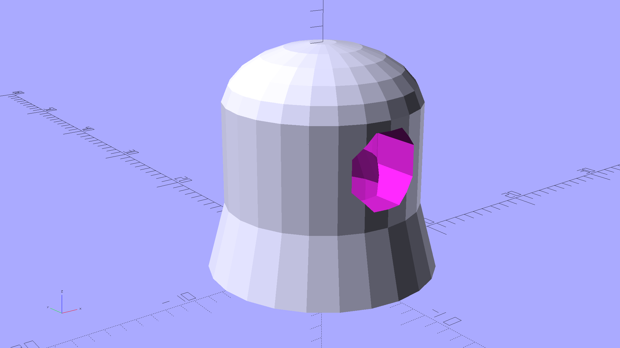
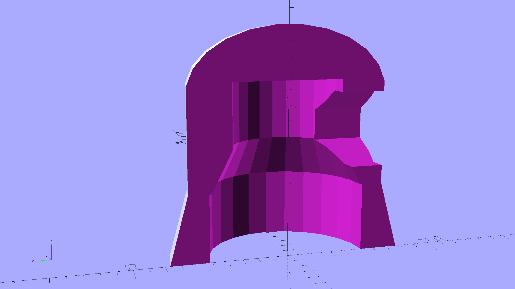
    COB LED Heatsink mount - Slic3r
    COB LED Heatsink mount – Slic3r

    The Hilbert Curve infill on the top produces a textured finish; I’m a sucker for that pattern.

    The old lamp base isn’t particularly stylin’, but the new head lights up my desk below the big monitors without any glare:

    COB LED Desk Lamp - overview
    COB LED Desk Lamp – overview

    Now, let’s see how long this one lasts…

    The OpenSCAD source code as a Github gist:

    // Chip-on-board LED light heatsink mount for desk lamp
    // Ed Nisley KE4ZNU December 2015
    Layout = "Show"; // Show Build
    //- Extrusion parameters must match reality!
    ThreadThick = 0.25;
    ThreadWidth = 0.40;
    HoleWindage = 0.2;
    Protrusion = 0.1; // make holes end cleanly
    inch = 25.4;
    function IntegerMultiple(Size,Unit) = Unit * ceil(Size / Unit);
    //———————-
    // Dimensions
    ID = 0; // for round things
    OD = 1;
    LENGTH = 2;
    Gooseneck = [3.0,5.0,15.0]; // anchor for end of gooseneck
    COB = [25.0,23.0,2.5]; // Chip-on-board LED module
    Heatsink = [35.5,31.5,4.0]; // height is solid base bottom
    HSWire = [23.0,28.0,53.3]; // anchor width OC, width OAL, length OC
    HSWireDia = 1.4;
    HSLip = 1.0; // width of lip under heatsink
    BaseMargin = 2*2*ThreadWidth;
    BaseRadius = Gooseneck[OD]; // 2 x gooseneck = enough anchor, sets slab thickness
    BaseSides = 2*4;
    Base = [(Gooseneck[LENGTH] + Gooseneck[OD] + Heatsink[0] + 2*BaseRadius + BaseMargin),
    (Heatsink[1] + 2*BaseRadius + 2*BaseMargin),
    2*BaseRadius];
    //———————-
    // Useful routines
    module PolyCyl(Dia,Height,ForceSides=0) { // based on nophead's polyholes
    Sides = (ForceSides != 0) ? ForceSides : (ceil(Dia) + 2);
    FixDia = Dia / cos(180/Sides);
    cylinder(r=(FixDia + HoleWindage)/2,
    h=Height,
    $fn=Sides);
    }
    //– Lamp heatsink mount
    module Lamp() {
    difference() {
    translate([(Base[0]/2 – BaseRadius – Gooseneck[LENGTH]),0,0])
    hull()
    for (i=[-1,1], j=[-1,1])
    translate([i*(Base[0]/2 – BaseRadius),j*(Base[1]/2 – BaseRadius),Base[2]/2])
    sphere(r=BaseRadius/cos(180/BaseSides),$fn=BaseSides);
    translate([(Heatsink[0]/2 + Gooseneck[OD]),0,Heatsink[2] + COB[2]]) // main heatsink recess
    scale([1,1,2])
    cube((Heatsink + [HoleWindage,HoleWindage,0.0]),center=true);
    translate([(Heatsink[0]/2 + Gooseneck[OD]),0,Heatsink[2] – Protrusion]) // lower lip to shade lamp module
    scale([1,1,2])
    cube(Heatsink – [2*HSLip,2*HSLip,0],center=true);
    translate([0,0,Base[2]/2]) // goooseneck insertion
    rotate([0,-90,0]) rotate(180/8)
    PolyCyl(Gooseneck[OD],Base[0],8);
    translate([0,0,Base[2]/2 + Gooseneck[ID]/2]) // wire exit
    rotate([180,0,0])
    PolyCyl(Gooseneck[ID],Base[2],6);
    translate([Gooseneck[OD],0,(COB[2] – Protrusion)/2]) // wire slot
    rotate([180,0,0])
    cube([2*Gooseneck[OD],Gooseneck[ID],(COB[2] + Protrusion)],center=true);
    }
    }
    //———————-
    // Build it
    if (Layout == "Show") {
    Lamp();
    }
    if (Layout == "Build") {
    }
  • Tools for Ladies

    Wandering through the Sears tool department, I found this corner:

    Sears Pink Box Tools
    Sears Pink Box Tools

    Neither of the Ladies in my life favor pink, so I wasn’t even tempted…

    Mary wonders if the designers scaled the grips and spring tensions to suit women’s hands. Her experience shows that “tools for men” are too big and require too much grip strength for her comfort; applying pink plastic won’t improve them in the least.

  • Kenmore Progressive Vacuum Cleaner: Improved Suction Control

    The Suction Control slider on the handle of our shiny new Kenmore Progressive vacuum cleaner varies the speed of the howling motor in the base unit, rather than venting more or less air into the pipe. We like that, but it’s all too easy to inadvertently slide the control and never notice it, sooo I marked the default condition:

    Kenmore Progressive Vacuum - visible suction slider
    Kenmore Progressive Vacuum – visible suction slider

    Although every vacuum cleaner we’ve ever owned has touted its “quiet operation”, we always wear 30 dB ear muffs and it’s sometimes hard to tell the difference between full throttle and not quite so fast…

  • Bike Helmet Earbud Replacement

    A bag arrived from halfway around the planet, bearing five sets of cheap earbuds. There was no way to tell from the eBay description, but they’re vented on the side:

    Cheap earbud - side vent detail
    Cheap earbud – side vent detail

    And also to the rear, down inside those deep slots below the chromed plastic cover:

    Cheap earbud - back openings
    Cheap earbud – back openings

    The raised lettering is a nice touch; the other earbud has a script L.

    The PET braid over the fragile wire should withstand a bit more abuse than usual. The strain relief isn’t anything to cheer, though, consisting of that rectangular channel with the wire loose inside. I figured I’d start minimal and fix whatever crops up; I have nine more earbuds to go.

    The motivation for all this was having the Gorilla Tape peel off the helmet, leaving a hardened mass of glue behind, then snagging the earbud wires. This is the new, somewhat better protected, wiring:

    Bell Helmet - mic-earbud wire - hardened tape adhesive
    Bell Helmet – mic-earbud wire – hardened tape adhesive

    In a triumph of hope over experience, I applied more Gorilla Tape:

    Bell Helmet - re-taped mic-earbud wiring
    Bell Helmet – re-taped mic-earbud wiring

    The helmet may need replacing after another iteration or two.

    My solid modeling hand has become stronger these days, so I should gimmick up a flat-ish wart anchoring the mic boom and all the wiring to the helmet shell.

  • Slic3r vs. Sequential 3D Printing

    The tiny posts on the fencing helmet ear grommet produced a remarkable amount of PETG hair, because the nozzle had to skip between four separate pieces on the platform at each layer:

    So I told Slic3r to build each part separately:

    Fencing helmet grommet - separate builds - first attempt
    Fencing helmet grommet – separate builds – first attempt

    Due to absolutely no forethought or planning on my part, that actually worked. Slic3r defines a cylindrical keep-out zone around the nozzle that I set to 15 mm radius and 25 mm height, but those numbers are completely wrong for the M2, particularly with a V4 hot end.

    To the rear, the nuts & bolts along the bottom of the X gantry sit 5 mm above the V4 nozzle, with the relaxed actuator on my re-relocated Z-axis home switch at Z=+1 mm:

    V4 PETG - extruder priming
    V4 PETG – extruder priming

    To the front, the bed fan doesn’t sit much higher:

    M2 V4 Extruder - 24 V fans
    M2 V4 Extruder – 24 V fans

    As it turned out, the front washers built first, sitting there in front of the gantry and behind the fan, the rear washers appeared last, and Everything Just Worked.

    However, even though the M2’s layout won’t allow for automated layout, I figured I could do it manually by building the parts from front to rear:

    Fencing Helmet Ear Grommet - Slic3r layout
    Fencing Helmet Ear Grommet – Slic3r layout

    That way, the already-built parts never pass under the gantry / switch. For particularly tall parts, I could remove / relocate the bed fan to clear the already-built parts as they appear.

    Come to find out that Slic3r, for whatever reason, doesn’t build the parts in the order you’d expect from the nice list on the far right side of the screen:

    Sequential Build Order - Slic3r vs Pronterface
    Sequential Build Order – Slic3r vs Pronterface

    Worse, the Slic3r 3D preview shows the threads by layer (which is what you’d expect), rather than by object for sequential builds:

    Slic3r - sequential preview vs build order
    Slic3r – sequential preview vs build order

    I don’t know how you’d force-fit a four-dimensional preview into the UI, so I won’t complain at all.

    There’s no way to tell which part will build first; selecting the part will highlight its entry in the list (and vice versa), but the order of appearance in that list doesn’t tell you where the G-Code will appear in the output file. That’s not a problem for extruders with a keep-out volume that looks like a cylinder, so there’s no reason for Slic3r to do it any differently: it will manage the extruder position to clear all the objects in any order.

    The Pronterface preview creates the objects by reading the G-Code file and displaying the threads in order, so, if you’re quick and it’s slow, you can watch the parts appear in their to-be-built order. The detailed preview (in the small window on the right in the screenshot) does show the parts in the order they will be built as you scroll upward through the “layers”, which is the only way you can tell what will happen.

    So doing sequential builds requires iterating through these steps until the right answer appears:

    •  Add all objects separately to get each one as a separate line in the list to the right
      • Using the More option to duplicate objects produces multiple objects per line = Bad Idea
    • Arrange objects in a line from front to back
    • Export G-Code file
    • Load G-Code file into Pronterface
    • Pop up the Pronterface layer preview, scroll upward to show build order, note carefully
    • Rearrange parts in Slic3r accordingly

    That’s do-able (note the different order from the Slic3r preview):

    Fencing helmet grommet - manual sequential build
    Fencing helmet grommet – manual sequential build

    But it’s tedious and enough of a pain that it probably makes no sense for anything other than parts that you absolutely can’t build any other way.

    In this case, completing each of the bottom washers separately eliminated all of the PETG hair between the small pegs. The upper washers still had some hair inside the inner cylinder, but not much. If you were fussy, you could suppress that by selecting “Avoid crossing perimeters”, at the cost of more flailing around in the XY plane.

    All those spare grommets will make a good show-n-tell exhibit…

  • Blue Gauntlet Fencing Helmet Ear Grommet

    Our Larval Engineer practiced fencing for several years, learning the fundamental truth that you should always bring a gun to a knife fight:

    Fencing - taking a hit
    Fencing – taking a hit

    It’s time to pass the gear along to someone who can use it, but we discovered one of the ear grommets inside the helmet had broken:

    Blue Gauntlet M003-BG Helmet - broken ear grommet
    Blue Gauntlet M003-BG Helmet – broken ear grommet

    The cylinder in the middle should be attached to the washer on the left, which goes inside the helmet padding. It’s a tight push fit inside the washer on the right, which goes on the outside of the padding. Ridges along the cylinder hold it in place.

    Being an injection-molded polyethylene part, no earthly adhesive or solvent will bother it, soooo… the solid model pretty much reproduces the original design:

    Fencing Helmet Ear Grommet - show
    Fencing Helmet Ear Grommet – show

    The top washer goes inside the padding against your (well, her) ear, so I chamfered the edges sorta-kinda like the original.

    There are no deliberate ridges on the central cylinder, but printing the parts in the obvious orientation with no additional clearance makes them a very snug push fit and the usual 3D printing ridges work perfectly; you could apply adhesive if you like. The outside washer has a slight chamfer to orient the post and get it moving along.

    The posts keep the whole affair from rotating, but I’m not sure they’re really necessary.

    Printing a pair doesn’t take much longer than just one:

    Fencing Helmet Ear Grommet - build
    Fencing Helmet Ear Grommet – build

    It doesn’t look like much inside the helmet:

    Blue Gauntlet M003-BG - replacement ear grommet - installed
    Blue Gauntlet M003-BG – replacement ear grommet – installed

    The OpenSCAD source code as a gist from Github:

    // Fencing Helmet Ear Grommet
    // Ed Nisley KE4ZNU December 2015
    // Layout options
    Layout = "Show"; // Base Cap Build Show
    //- Extrusion parameters must match reality!
    // Print with +1 shells and 3 solid layers
    ThreadThick = 0.20;
    ThreadWidth = 0.40;
    HoleWindage = 0.2;
    function IntegerMultiple(Size,Unit) = Unit * ceil(Size / Unit);
    Protrusion = 0.1; // make holes end cleanly
    //———————-
    // Dimensions
    NumSides = 12*4;
    $fn = NumSides;
    //———————-
    // Useful routines
    module PolyCyl(Dia,Height,ForceSides=0) { // based on nophead's polyholes
    Sides = (ForceSides != 0) ? ForceSides : (ceil(Dia) + 2);
    FixDia = Dia / cos(180/Sides);
    cylinder(r=(FixDia + HoleWindage)/2,
    h=Height,
    $fn=Sides);
    }
    //——————-
    // Parts
    // Base on outside of liner
    PostOD = 15.5;
    PostLength = 8.0;
    BaseOD = 26.0;
    BaseLength = 3.4;
    module Base() {
    difference() {
    union() {
    cylinder(d=BaseOD,h=2.0);
    cylinder(d=20.0,h=BaseLength);
    for (i=[0:5])
    rotate(i*360/6)
    translate([11.5,0,0])
    rotate(180/6)
    cylinder(d1=2.5,d2=3*ThreadWidth,h=4.0,$fn=6);
    }
    translate([0,0,-Protrusion])
    // PolyCyl(PostOD,4.0,NumSides/4);
    cylinder(d=PostOD,h=PostLength,$fn=NumSides/4);
    translate([0,0,(BaseLength – 4*ThreadThick)])
    cylinder(d1=PostOD,d2=(PostOD + 2*ThreadWidth),h=(4*ThreadThick + Protrusion),$fn=NumSides/4);
    }
    }
    // Cap inside liner
    CapID = 12.0;
    CapOD = 28.0;
    CapThick = 3.0;
    module Cap() {
    difference() {
    union() {
    rotate_extrude(convexity=2)
    polygon(points=[
    [CapID/2 + CapThick/3,0.0],
    [CapOD/2 – CapThick/3,0.0],
    [CapOD/2,CapThick/2],
    [CapOD/2,CapThick],
    [CapID/2,CapThick],
    [CapID/2,CapThick – CapThick/3]
    ]);
    translate([0,0,CapThick – Protrusion])
    cylinder(d=PostOD,h=(PostLength – (CapThick – Protrusion)),$fn=NumSides/4);
    }
    translate([0,0,-Protrusion])
    PolyCyl(CapID,10.0,$fn);
    }
    }
    //———————-
    // Build it!
    if (Layout == "Base")
    Base();
    if (Layout == "Cap")
    Cap();
    BuildSpace = 30/2;
    if (Layout == "Build") {
    for (j=[-1,1])
    translate([j*BuildSpace,0,0]) {
    translate([0,-BuildSpace,0])
    Base();
    translate([0,BuildSpace,0])
    Cap();
    }
    }
    if (Layout == "Show") {
    color("LightGreen") Base();
    translate([0,0,12])
    rotate([180,0,0])
    color("LightBlue") Cap();
    }

  • Kenmore Progressive Vacuum Cleaner vs. Classic Electrolux Dust Brush

    Vacuum cleaner dust brushes, separated by millimeters and decades:

    Kenmore vs adapted Electrolux dust brushes
    Kenmore vs adapted Electrolux dust brushes

    The bulky one on the left came with our new Kenmore Progressive vacuum cleaner. It’s fine for dust on a flat horizontal or vertical surface and totally useless for dust on actual objects. It’s supposed to snap around the handle at the end of the cleaner’s flexy hose, where it helps make the entire assembly too large and too clumsy, or on the end of the “wand”, where it’s at the wrong angle. The bonus outer shell slides around the stubby bristles in the unlikely event they’re too long for the flat surface at hand.

    The brush on the right emerged from the Box o’ Electrolux Parts that Came With The House™, must be half a century old, and consists of a cast aluminum lump with various holes milled into it, adorned with luxuriously long and flexible horsehair. Suffice it to say they don’t make ’em like that any more. Heck, they probably don’t make horses with hair like that any more, either.

    The blue plastic adapter atop the aluminum ball looks like you’d expect by now:

    Electrolux Brush Adapter
    Electrolux Brush Adapter

    The short snout fits neatly into the space available inside the ball. The abrupt ledge at the top of the snout, of course, didn’t work well; I rushed the design for a show-n-tell.

    The OpenSCAD source code (as a Github gist) bevels that ledge and tweaks the interior air channel a bit:

    // Kenmore vacuum cleaner nozzle adapters
    // Ed Nisley KE4ZNU December 2015
    // Layout options
    Layout = "LuxBrush"; // MaleFitting CoilWand FloorBrush CreviceTool ScrubbyTool LuxBrush
    //- Extrusion parameters must match reality!
    // Print with +1 shells and 3 solid layers
    ThreadThick = 0.25;
    ThreadWidth = 0.40;
    HoleWindage = 0.2;
    function IntegerMultiple(Size,Unit) = Unit * ceil(Size / Unit);
    Protrusion = 0.1; // make holes end cleanly
    //———————-
    // Dimensions
    ID1 = 0; // for tapered tubes
    ID2 = 1;
    OD1 = 2;
    OD2 = 3;
    LENGTH = 4;
    OEMTube = [35.0,35.0,41.7,40.5,30.0]; // main fitting tube
    EndStop = [OEMTube[ID1],OEMTube[ID2],47.5,47.5,6.5]; // flange at end of main tube
    FittingOAL = OEMTube[LENGTH] + EndStop[LENGTH];
    $fn = 12*4;
    //———————-
    // Useful routines
    module PolyCyl(Dia,Height,ForceSides=0) { // based on nophead's polyholes
    Sides = (ForceSides != 0) ? ForceSides : (ceil(Dia) + 2);
    FixDia = Dia / cos(180/Sides);
    cylinder(r=(FixDia + HoleWindage)/2,
    h=Height,
    $fn=Sides);
    }
    //——————-
    // Male fitting on end of Kenmore tools
    // This slides into the end of the handle or wand and latches firmly in place
    module MaleFitting() {
    Latch = [40,11.5,5.0]; // rectangle latch opening
    EntryAngle = 45; // latch entry ramp
    EntrySides = 16;
    EntryHeight = 15.0; // lower edge on *inside* of fitting
    KeyRadius = 1.0;
    translate([0,0,6.5])
    difference() {
    union() {
    cylinder(d1=OEMTube[OD1],d2=OEMTube[OD2],h=OEMTube[LENGTH]); // main tube
    hull() // insertion guide
    for (i=[-(6.0/2 – KeyRadius),(6.0/2 – KeyRadius)],
    j=[-(28.0/2 – KeyRadius),(28.0/2 – KeyRadius)],
    k=[-(26.0/2 – KeyRadius),(26.0/2 – KeyRadius)])
    translate([(i – (OEMTube[ID1]/2 + OEMTube[OD1]/2)/2 + 6.0/2),j,(k + 26.0/2 – 1.0)])
    sphere(r=KeyRadius,$fn=8);
    translate([0,0,-EndStop[LENGTH]]) // wand tube butts against this
    cylinder(d=EndStop[OD1],h=EndStop[LENGTH] + Protrusion);
    }
    translate([0,0,-OEMTube[LENGTH]]) // main bore
    cylinder(d=OEMTube[ID1],h=2*OEMTube[LENGTH] + 2*Protrusion);
    translate([0,-11.5/2,23.0 – 5.0]) // latch opening
    cube(Latch);
    translate([OEMTube[ID1]/2 + EntryHeight/tan(90-EntryAngle),0,0]) // latch ramp
    translate([(Latch[1]/cos(180/EntrySides))*cos(EntryAngle)/2,0,(Latch[1]/cos(180/EntrySides))*sin(EntryAngle)/2])
    rotate([0,-EntryAngle,0])
    intersection() {
    rotate(180/EntrySides)
    PolyCyl(Latch[1],Latch[0],EntrySides);
    translate([-(2*Latch[0])/2,0,-Protrusion])
    cube(2*Latch[0],center=true);
    }
    }
    }
    //——————-
    // Refrigerator evaporator coil wand
    module CoilWand() {
    union() {
    translate([0,0,50.0])
    rotate([180,0,0])
    difference() {
    cylinder(d1=EndStop[OD1],d2=42.0,h=50.0);
    translate([0,0,-Protrusion])
    cylinder(d1=35.0,d2=35.8,h=100);
    }
    translate([0,0,50.0 – Protrusion])
    MaleFitting();
    }
    }
    //——————-
    // Refrigerator evaporator coil wand
    module FloorBrush() {
    union() {
    translate([0,0,60.0])
    rotate([180,0,0])
    difference() {
    union() {
    cylinder(d1=EndStop[OD1],d2=32.4,h=10.0);
    translate([0,0,10.0 – Protrusion])
    cylinder(d1=32.4,d2=30.7,h=50.0 + Protrusion);
    }
    translate([0,0,-Protrusion])
    cylinder(d1=28.0,d2=24.0,h=100);
    }
    translate([0,0,60.0 – Protrusion])
    MaleFitting();
    }
    }
    //——————-
    // Crevice tool
    module CreviceTool() {
    union() {
    translate([0,0,60.0])
    rotate([180,0,0])
    difference() {
    union() {
    cylinder(d1=EndStop[OD1],d2=32.0,h=10.0);
    translate([0,0,10.0 – Protrusion])
    cylinder(d1=32.0,d2=30.4,h=50.0 + Protrusion);
    }
    translate([0,0,-Protrusion])
    cylinder(d1=28.0,d2=24.0,h=100);
    }
    translate([0,0,60.0 – Protrusion])
    MaleFitting();
    }
    }
    //——————-
    // Mystery brush
    module ScrubbyTool() {
    union() {
    translate([0,0,60.0])
    rotate([180,0,0])
    difference() {
    union() {
    cylinder(d1=EndStop[OD1],d2=31.8,h=10.0);
    translate([0,0,10.0 – Protrusion])
    cylinder(d1=31.8,d2=31.0,h=50.0 + Protrusion);
    }
    translate([0,0,-Protrusion])
    cylinder(d1=26.0,d2=24.0,h=100);
    }
    translate([0,0,60.0 – Protrusion])
    MaleFitting();
    }
    }
    //——————-
    // Electrolux brush ball
    module LuxBrush() {
    union() {
    translate([0,0,30.0])
    rotate([180,0,0])
    difference() {
    union() {
    cylinder(d1=EndStop[OD1],d2=30.8,h=10.0);
    translate([0,0,10.0 – Protrusion])
    cylinder(d1=30.8,d2=30.0,h=20.0 + Protrusion);
    }
    translate([0,0,-Protrusion])
    cylinder(d1=25.0,d2=23.0,h=30 + 2*Protrusion);
    }
    translate([0,0,30.0 – Protrusion])
    MaleFitting();
    }
    }
    //———————-
    // Build it!
    if (Layout == "MaleFitting")
    MaleFitting();
    if (Layout == "CoilWand")
    CoilWand();
    if (Layout == "FloorBrush")
    FloorBrush();
    if (Layout == "CreviceTool")
    CreviceTool();
    if (Layout == "ScrubbyTool")
    ScrubbyTool();
    if (Layout == "LuxBrush")
    LuxBrush();

    That’s  supposed to prevent the WordPress post editors from destroying the formatting…