|
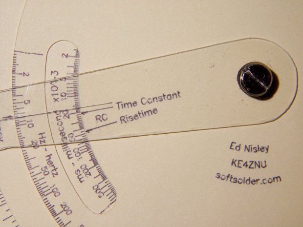
// Tektronix Circuit Computer Reproduction |
|
// Ed Nisley KE4ZNU – 2019-11 |
|
|
|
//—– |
|
// Library routines |
|
|
|
include("tracepath.inc.gcmc"); |
|
include("engrave.inc.gcmc"); |
|
|
|
TekOD = to_mm(7.75in); // orginal Tek Circuit Computer diameter |
|
|
|
FALSE = 0; |
|
TRUE = 1; |
|
|
|
//—– |
|
// Command line parameters |
|
|
|
// -D various useful tidbits |
|
// add unit to speeds and depths: 2000mm / -3.00mm / etc |
|
|
|
if (!isdefined("BaseOD")) { |
|
BaseOD = TekOD; |
|
} |
|
comment("Base OD: ",BaseOD); |
|
|
|
SizeRatio = BaseOD / TekOD; // overall scaling for different base diameters |
|
comment(" scale factor: ",SizeRatio); |
|
|
|
if (!isdefined("SelectPart")) { |
|
SelectPart = "Bottom"; |
|
} |
|
comment("Part: ",SelectPart); |
|
|
|
if (!isdefined("Operation")) { |
|
Operation = "Engrave"; |
|
} |
|
comment("Operation: ",Operation); |
|
|
|
if (!isdefined("ScaleSpeed")) { |
|
ScaleSpeed = 2400mm; |
|
} |
|
|
|
if (!isdefined("TextSpeed")) { |
|
TextSpeed = 2400mm; |
|
} |
|
|
|
// Engraving & drag knife force is proportional to depth, but you must know the coefficent! |
|
|
|
if (!isdefined("EngraveZ")) { |
|
EngraveZ = -1.0mm; |
|
} |
|
|
|
if (!isdefined("KnifeZ")) { |
|
KnifeZ = -2.0mm; |
|
} |
|
|
|
if (!isdefined("KnifeSpeed")) { |
|
KnifeSpeed = 1000mm; |
|
} |
|
|
|
//—– |
|
// Define useful constants |
|
|
|
SafeZ = 10.00mm; // above all obstructions |
|
TravelZ = 1.00mm; // within engraving area |
|
|
|
//—– |
|
// Overall values |
|
|
|
ScaleHeight = to_inch(3.0/8.0) * SizeRatio; // scale-to-scale distance |
|
WindowHeight = ScaleHeight; // cutout window opening |
|
|
|
DeckBottomOD = BaseOD; // deck sizes depend on scale height |
|
DeckMiddleOD = DeckBottomOD – 2*ScaleHeight; |
|
DeckTopOD = DeckMiddleOD – 2*(ScaleHeight + WindowHeight); |
|
|
|
ScaleArc = 18deg; // angular length of one decade: +CCW |
|
ScaleExdent = 0.20; // log spacing at end of scales to identifiers |
|
|
|
Scale2Pi = log10(2*pi()) * ScaleArc; // angular offset for scales using 2*pi |
|
ScaleRT = log10(2.197225) * ScaleArc; // angular offset for risetime |
|
|
|
TauAngle = 150deg; // arbitrary offset to 1.0 on tau scales |
|
TitleAngle = -50deg; // … to Tek title, then +180deg to logo |
|
|
|
INWARD = -1; // text and tick alignment (used as integers) |
|
OUTWARD = 1; |
|
|
|
TEXT_LEFT = -1; // text justification |
|
TEXT_CENTERED = 0; |
|
TEXT_RIGHT = 1; |
|
|
|
TextFont = FONT_HSANS_1_RS; |
|
|
|
TitleTextSize = 3.1 * SizeRatio * [1.0mm,1.0mm]; |
|
LegendTextSize = 1.8 * SizeRatio * [1.0mm,1.0mm]; |
|
ScaleTextSize = 1.4 * SizeRatio * [1.0mm,1.0mm]; |
|
|
|
//—- |
|
// Define tick layout for scales |
|
// Numeric values = scale position, tick length |
|
// These are not algorithmic! |
|
|
|
TickMajor = 3.2mm * SizeRatio; // length of tick marks |
|
TickMid = 1.9mm * SizeRatio; |
|
TickMinor = 1.2mm * SizeRatio; |
|
|
|
TickScaleNarrow = { |
|
[1.0,TickMajor], |
|
[1.1,TickMinor],[1.2,TickMinor],[1.3,TickMinor],[1.4,TickMinor], |
|
[1.5,TickMid], |
|
[1.6,TickMinor],[1.7,TickMinor],[1.8,TickMinor],[1.9,TickMinor], |
|
[2.0,TickMajor], |
|
[2.2,TickMinor],[2.4,TickMinor],[2.6,TickMinor],[2.8,TickMinor], |
|
[3.0,TickMajor], |
|
[3.2,TickMinor],[3.4,TickMinor],[3.6,TickMinor],[3.8,TickMinor], |
|
[4.0,TickMajor], |
|
[4.5,TickMinor], |
|
[5.0,TickMajor], |
|
[5.5,TickMinor], |
|
[6.0,TickMajor], |
|
[6.5,TickMinor], |
|
[7.0,TickMajor], |
|
[7.5,TickMinor], |
|
[8.0,TickMajor], |
|
[8.5,TickMinor], |
|
[9.0,TickMajor], |
|
[9.5,TickMinor] |
|
}; |
|
|
|
TickScaleWide = { |
|
[1.0,TickMajor], |
|
[1.1,TickMinor],[1.2,TickMinor],[1.3,TickMinor],[1.4,TickMinor], |
|
[1.5,TickMid], |
|
[1.6,TickMinor],[1.7,TickMinor],[1.8,TickMinor],[1.9,TickMinor], |
|
[2.0,TickMajor], |
|
[2.1,TickMinor],[2.2,TickMinor],[2.3,TickMinor],[2.4,TickMinor], |
|
[2.5,TickMid], |
|
[2.6,TickMinor],[2.7,TickMinor],[2.8,TickMinor],[2.9,TickMinor], |
|
[3.0,TickMajor], |
|
[3.2,TickMinor],[3.4,TickMinor],[3.6,TickMinor],[3.8,TickMinor], |
|
[4.0,TickMajor], |
|
[4.2,TickMinor],[4.4,TickMinor],[4.6,TickMinor],[4.8,TickMinor], |
|
[5.0,TickMajor], |
|
[5.5,TickMinor], |
|
[6.0,TickMajor], |
|
[6.5,TickMinor], |
|
[7.0,TickMajor], |
|
[7.5,TickMinor], |
|
[8.0,TickMajor], |
|
[8.5,TickMinor], |
|
[9.0,TickMajor], |
|
[9.5,TickMinor] |
|
}; |
|
|
|
TickLabels = [1,2,5]; // labels only these ticks, must be integers |
|
TickGap = 0.50 * ScaleTextSize.y; // gap between text and ticks |
|
|
|
PivotOD = 5.0mm; // center bolt OD |
|
|
|
Legend1 = "Ed Nisley – KE4ZNU"; |
|
Legend2 = "softsolder.com"; |
|
|
|
|
|
//—————————————————————————– |
|
// Text & Scale Engraving |
|
|
|
//—– |
|
// Write text on a radial line |
|
|
|
function RadialText(TextPath,CenterPt,Radius,Angle,Justify,Orient) { |
|
|
|
local pl = TextPath[-1].x; // path length |
|
|
|
local ji = (Justify == TEXT_LEFT) ? 0mm : // justification, assume OUTWARD |
|
(Justify == TEXT_CENTERED) ? -pl/2 : |
|
(Justify == TEXT_RIGHT) ? -pl : |
|
0mm; |
|
|
|
if (Orient == INWARD) { |
|
TextPath = rotate_xy(TextPath,180deg); |
|
ji = -ji; |
|
} |
|
|
|
TextPath += [Radius + ji,0mm]; |
|
|
|
return rotate_xy(TextPath,Angle) + CenterPt; |
|
|
|
} |
|
|
|
//—– |
|
// Draw a radial legend |
|
// Offset in units of char height: 0 = baseline on radius, +/- = above/below |
|
|
|
function RadialLegend(Text,Center,Radius,Angle,Justify,Orient,Offset) { |
|
|
|
local tp = scale(typeset(Text,TextFont),LegendTextSize) + [0mm,Offset * LegendTextSize.y]; |
|
local tpr = RadialText(tp,Center,Radius,Angle,Justify,Orient); |
|
|
|
feedrate(TextSpeed); |
|
engrave(tpr,TravelZ,EngraveZ); |
|
|
|
} |
|
|
|
//—– |
|
// Bend text around an arc |
|
|
|
function ArcText(TextPath,CenterPt,Radius,BaseAngle,Justify,Orient) { |
|
|
|
local pl = TextPath[-1].x; // path length |
|
local c = 2*pi()*Radius; |
|
local ta = to_deg(360 * pl / c); // subtended angle |
|
|
|
local ja = (Justify == TEXT_LEFT ? 0deg : // assume OUTWARD |
|
(Justify == TEXT_CENTERED) ? -ta / 2 : |
|
(Justify == TEXT_RIGHT) ? -ta : |
|
0deg); |
|
|
|
ja = BaseAngle + Orient*ja; |
|
|
|
local ArcPath = {}; |
|
|
|
local pt,r,a; |
|
foreach(TextPath; pt) { |
|
if (!isundef(pt.x) && !isundef(pt.y) && isundef(pt.z)) { // XY motion, no Z |
|
r = (Orient == OUTWARD) ? Radius – pt.y : Radius + pt.y; |
|
a = Orient * 360deg * (pt.x / c) + ja; |
|
ArcPath += {[r*cos(a) + CenterPt.x, r*sin(a) + CenterPt.y,-]}; |
|
} |
|
elif (isundef(pt.x) && isundef(pt.y) && !isundef(pt.z)) { // no XY, Z up/down |
|
ArcPath += {pt}; |
|
} |
|
else { |
|
error("ArcText – Point is not pure XY or pure Z: " + to_string(pt)); |
|
} |
|
} |
|
|
|
return ArcPath; |
|
|
|
} |
|
|
|
|
|
|
|
//—– |
|
// Draw scale legend |
|
|
|
function ArcLegend(Text,Radius,Angle,Orient) { |
|
|
|
local tp = scale(typeset(Text,TextFont),LegendTextSize); |
|
local tpa = ArcText(tp,[0mm,0mm],Radius,Angle,TEXT_CENTERED,Orient); |
|
|
|
feedrate(TextSpeed); |
|
engrave(tpa,TravelZ,EngraveZ); |
|
|
|
} |
|
|
|
|
|
//—– |
|
// Draw a decade of ticks & labels |
|
// ArcLength > 0 = CCW, < 0 = CW |
|
// UnitOnly forces just the unit tick, so as to allow creating the last tick of the scale |
|
|
|
function DrawTicks(Radius,TickMarks,TickOrient,UnitAngle,ArcLength,Decade,LabelOrient,UnitOnly) { |
|
|
|
feedrate(ScaleSpeed); |
|
|
|
local a,r0,r1,p0,p1; |
|
|
|
if (Decade == 1 || UnitOnly) { // draw unit marker |
|
a = UnitAngle; |
|
r0 = Radius + TickOrient * (TickMajor + 2*TickGap + ScaleTextSize.y); |
|
p0 = r0 * [cos(a),sin(a)]; |
|
r1 = Radius + TickOrient * (ScaleHeight – 2*TickGap); |
|
p1 = r1 * [cos(a),sin(a)]; |
|
|
|
goto(p0); |
|
move([-,-,EngraveZ]); |
|
move(p1); |
|
goto([-,-,TravelZ]); |
|
} |
|
|
|
local ticklist = UnitOnly ? {TickMarks[0]} : TickMarks; |
|
|
|
local tick; |
|
foreach(ticklist; tick) { |
|
a = UnitAngle + ArcLength * log10(tick[0]); |
|
p0 = Radius * [cos(a), sin(a)]; |
|
p1 = (Radius + TickOrient*tick[1]) * [cos(a), sin(a)]; |
|
|
|
goto(p0); |
|
move([-,-,EngraveZ]); |
|
move(p1); |
|
goto([-,-,TravelZ]); |
|
} |
|
|
|
feedrate(TextSpeed); // draw scale values |
|
|
|
local lrad = Radius + TickOrient * (TickMajor + TickGap); |
|
|
|
if (TickOrient == INWARD) { |
|
if (LabelOrient == INWARD) { |
|
lrad -= ScaleTextSize.y; // inward ticks + inward labels = offset inward |
|
} |
|
} |
|
else { |
|
if (LabelOrient == OUTWARD) { |
|
lrad += ScaleTextSize.y; // outward ticks + outward labels = offset outward |
|
} |
|
} |
|
|
|
ticklist = UnitOnly ? [TickLabels[0]] : TickLabels; |
|
|
|
local ltext,lpath,tpa; |
|
foreach(ticklist; tick) { |
|
ltext = to_string(Decade * to_int(tick)); |
|
lpath = scale(typeset(ltext,TextFont),ScaleTextSize); |
|
a = UnitAngle + ArcLength * log10(tick); |
|
tpa = ArcText(lpath,[0mm,0mm],lrad,a,TEXT_CENTERED,LabelOrient); |
|
engrave(tpa,TravelZ,EngraveZ); |
|
} |
|
|
|
} |
|
|
|
//—– |
|
// Mark key locations |
|
|
|
function MarkPivot() { |
|
|
|
comment("Mark center point"); |
|
feedrate(ScaleSpeed); |
|
|
|
if (TRUE) { |
|
goto([-,-,SafeZ]); |
|
goto([PivotOD/2,0,-]); |
|
move([-,-,EngraveZ]); |
|
circle_cw([0,0]); // outline pivot |
|
|
|
move([-PivotOD/2,0,-]); // draw X line |
|
goto([-,-,TravelZ]); |
|
goto([0,PivotOD/2,-]); |
|
move([-,-,EngraveZ]); |
|
move ([0,-PivotOD/2,-]); // draw Y line |
|
goto([-,-,TravelZ]); |
|
} |
|
|
|
} |
|
|
|
//—– |
|
// Draw attribution |
|
|
|
function DrawAttribution(AttribRad) { |
|
|
|
comment("Attribution at: ",AttribRad); |
|
|
|
feedrate(TextSpeed); |
|
|
|
local tp,tpa; |
|
if (Legend1) { |
|
tp = scale(typeset(Legend1,TextFont),TitleTextSize); |
|
tpa = ArcText(tp,[0mm,0mm],AttribRad,0deg,TEXT_CENTERED,OUTWARD); |
|
feedrate(TextSpeed); |
|
engrave(tpa,TravelZ,EngraveZ); |
|
} |
|
|
|
if (Legend2) { |
|
tp = scale(typeset(Legend2,TextFont),TitleTextSize); |
|
tpa = ArcText(tp,[0mm,0mm],AttribRad,180deg,TEXT_CENTERED,OUTWARD); |
|
feedrate(TextSpeed); |
|
engrave(tpa,TravelZ,EngraveZ); |
|
} |
|
|
|
if (FALSE) { // test code to verify ArcText |
|
comment("ArcText test"); |
|
ctr = [0mm,0mm]; |
|
|
|
tp = scale(typeset("Right Inward",TextFont),ScaleTextSize); |
|
tpa = ArcText(tp,ctr,30mm,45deg,TEXT_RIGHT,INWARD); |
|
engrave(tpa,TravelZ,EngraveZ); |
|
tp = scale(typeset("Right Outward",TextFont),ScaleTextSize); |
|
tpa = ArcText(tp,ctr,30mm,45deg,TEXT_RIGHT,OUTWARD); |
|
engrave(tpa,TravelZ,EngraveZ); |
|
|
|
tp = scale(typeset("Center Inward",TextFont),ScaleTextSize); |
|
tpa = ArcText(tp,ctr,20mm,45deg,TEXT_CENTERED,INWARD); |
|
engrave(tpa,TravelZ,EngraveZ); |
|
tp = scale(typeset("Center Outward",TextFont),ScaleTextSize); |
|
tpa = ArcText(tp,ctr,20mm,45deg,TEXT_CENTERED,OUTWARD); |
|
engrave(tpa,TravelZ,EngraveZ); |
|
|
|
tp = scale(typeset("Left Inward",TextFont),ScaleTextSize); |
|
tpa = ArcText(tp,ctr,10mm,45deg,TEXT_LEFT,INWARD); |
|
engrave(tpa,TravelZ,EngraveZ); |
|
tp = scale(typeset("Left Outward",TextFont),ScaleTextSize); |
|
tpa = ArcText(tp,ctr,10mm,45deg,TEXT_LEFT,OUTWARD); |
|
engrave(tpa,TravelZ,EngraveZ); |
|
|
|
goto([0mm,0mm,-]); |
|
move([40mm,40mm,-]); |
|
} |
|
|
|
if (FALSE) { // test code to verify RadialText |
|
comment("RadialText test"); |
|
ctr = [0mm,0mm]; |
|
r = 20mm; |
|
|
|
a = 0deg; |
|
tp = scale(typeset("Left Inward",TextFont),LegendTextSize); |
|
tpr = RadialText(tp,ctr,r,a,TEXT_LEFT,INWARD); |
|
feedrate(TextSpeed); |
|
engrave(tpr,TravelZ,EngraveZ); |
|
tp = scale(typeset("Left Outward",TextFont),LegendTextSize); |
|
tpr = RadialText(tp,ctr,r,a,TEXT_LEFT,OUTWARD); |
|
feedrate(TextSpeed); |
|
engrave(tpr,TravelZ,EngraveZ); |
|
|
|
a = 90deg; |
|
tp = scale(typeset("Right Inward",TextFont),LegendTextSize); |
|
tpr = RadialText(tp,ctr,r,a,TEXT_RIGHT,INWARD); |
|
feedrate(TextSpeed); |
|
engrave(tpr,TravelZ,EngraveZ); |
|
tp = scale(typeset("Right Outward",TextFont),LegendTextSize); |
|
tpr = RadialText(tp,ctr,r,a,TEXT_RIGHT,OUTWARD); |
|
feedrate(TextSpeed); |
|
engrave(tpr,TravelZ,EngraveZ); |
|
|
|
|
|
a = 180deg; |
|
tp = scale(typeset("Center Inward",TextFont),LegendTextSize); |
|
tpr = RadialText(tp,ctr,r,a,TEXT_CENTERED,INWARD); |
|
feedrate(TextSpeed); |
|
engrave(tpr,TravelZ,EngraveZ); |
|
tp = scale(typeset("Center Outward",TextFont),LegendTextSize); |
|
tpr = RadialText(tp,ctr,r,a,TEXT_CENTERED,OUTWARD); |
|
feedrate(TextSpeed); |
|
engrave(tpr,TravelZ,EngraveZ); |
|
|
|
a = 270deg; |
|
RadialLegend("Offset to radius",ctr,r,a,TEXT_CENTERED,INWARD,-0.5); |
|
goto(ctr); |
|
move([0,-2*r,EngraveZ]); |
|
|
|
goto([r,0mm,-]); |
|
circle_cw(ctr); |
|
|
|
} |
|
|
|
} |
|
|
|
//—————————————————————————– |
|
// Deck Engraving |
|
|
|
|
|
//———- |
|
// Engrave bottom deck |
|
|
|
function EngraveBottom() { |
|
|
|
// Mark center pivot |
|
|
|
MarkPivot(); |
|
|
|
comment("Inductance scale"); |
|
Radius = DeckRad – ScaleHeight; |
|
|
|
MinLog = -9; |
|
MaxLog = 6; |
|
Arc = -ScaleArc; |
|
|
|
dec = 1; |
|
offset = 0deg; |
|
for (logval = MinLog; logval < MaxLog; logval++) { |
|
a = offset + logval * Arc; |
|
DrawTicks(Radius,TickScaleNarrow,OUTWARD,a,Arc,dec,INWARD,FALSE); |
|
dec = (dec == 100) ? 1 : 10 * dec; |
|
} |
|
|
|
a = offset + MaxLog * Arc; |
|
DrawTicks(Radius,TickScaleNarrow,OUTWARD,a,Arc,1000,INWARD,TRUE); |
|
|
|
r = Radius + TickMajor + 2*TickGap + LegendTextSize.y; |
|
|
|
logval = MinLog + 1.5; |
|
a = offset + logval * Arc; |
|
ArcLegend("nH – nanohenry x10^-9",r,a,INWARD); |
|
|
|
logval += 3; |
|
a = offset + logval * Arc; |
|
ArcLegend("μH – microhenry x10^-6",r,a,INWARD); |
|
|
|
logval += 3; |
|
a = offset + logval * Arc; |
|
ArcLegend("mH – millihenry x10^-3",r,a,INWARD); |
|
|
|
logval += 3; |
|
a = offset + logval * Arc; |
|
ArcLegend("H – henry",r,a,INWARD); |
|
|
|
logval += 3; |
|
a = offset + logval * Arc; |
|
ArcLegend("kH – kilohenry x10^3",r,a,INWARD); |
|
|
|
r = Radius + TickMajor + TickGap; |
|
|
|
logval = MinLog – ScaleExdent; // scale identifiers |
|
a = offset + logval * Arc; |
|
tp = scale(typeset("L Scale →",TextFont),LegendTextSize); |
|
tpa = ArcText(tp,[0mm,0mm],r,a,TEXT_RIGHT,INWARD); |
|
engrave(tpa,TravelZ,EngraveZ); |
|
|
|
logval = MaxLog + ScaleExdent; |
|
a = offset + logval * Arc; |
|
tp = scale(typeset("← L Scale",TextFont),LegendTextSize); |
|
tpa = ArcText(tp,[0mm,0mm],r,a,TEXT_LEFT,INWARD); |
|
engrave(tpa,TravelZ,EngraveZ); |
|
|
|
comment("Inductive frequency scale"); |
|
|
|
Radius = DeckRad – 2*ScaleHeight; |
|
|
|
MinLog = 0; |
|
MaxLog = 9; |
|
Arc = 2*ScaleArc; // double-length scale for square roots |
|
|
|
dec = 1; |
|
offset = -(18 * ScaleArc – Scale2Pi); // using 18 degree arc length |
|
for (logval = MinLog; logval < MaxLog; logval++) { |
|
a = offset + logval * Arc; |
|
DrawTicks(Radius,TickScaleWide,OUTWARD,a,Arc,dec,OUTWARD,FALSE); |
|
dec = (dec == 100) ? 1 : 10 * dec; |
|
} |
|
|
|
a = offset + MaxLog * Arc; |
|
DrawTicks(Radius,TickScaleWide,OUTWARD,a,Arc,1000,OUTWARD,TRUE); |
|
|
|
feedrate(TextSpeed); // draw prefix legends |
|
|
|
r = Radius + TickMajor + 2*TickGap + 2*LegendTextSize.y; |
|
|
|
logval = MinLog + 0.5; |
|
|
|
for (i = 0; i < 3; i++) { |
|
a = offset + (i + logval) * Arc; |
|
ArcLegend("Hz – hertz",r,a,OUTWARD); |
|
} |
|
|
|
for (i = 3; i < 6; i++) { |
|
a = offset + (i + logval) * Arc; |
|
ArcLegend("kHz – kilohertz x10^3",r,a,OUTWARD); |
|
} |
|
|
|
for (i = 6; i < 9; i++) { |
|
a = offset + (i + logval) * Arc; |
|
ArcLegend("MHz – megahertz x10^6",r,a,OUTWARD); |
|
} |
|
|
|
r = Radius + TickMajor + TickGap + LegendTextSize.y; |
|
|
|
logval = MinLog – 0.5; // scale identifier |
|
a = offset + logval * Arc; |
|
ArcLegend("←——- FL Scale ——-→",r,a,OUTWARD); |
|
|
|
comment("Inductive TC / Risetime scale"); |
|
Radius = DeckRad – 3*ScaleHeight; |
|
|
|
MinLog = -12; |
|
MaxLog = 3; |
|
Arc = -ScaleArc; |
|
|
|
dec = 1; |
|
offset = -TauAngle; |
|
|
|
for (logval = MinLog; logval < MaxLog; logval++) { |
|
a = offset + logval * Arc; |
|
DrawTicks(Radius,TickScaleNarrow,OUTWARD,a,Arc,dec,INWARD,FALSE); |
|
dec = (dec == 100) ? 1 : 10 * dec; |
|
} |
|
|
|
a = offset + MaxLog * Arc; |
|
DrawTicks(Radius,TickScaleNarrow,OUTWARD,a,Arc,1000,INWARD,TRUE); |
|
|
|
feedrate(TextSpeed); // prefix legends |
|
|
|
r = Radius + TickMajor + 2*TickGap + LegendTextSize.y; |
|
|
|
logval = MinLog + 1.5; |
|
|
|
a = offset + logval * Arc; |
|
ArcLegend("ps – picosecond x10^-12",r,a,INWARD); |
|
|
|
logval += 3; |
|
a = offset + logval * Arc; |
|
ArcLegend("ns – nanosecond x10^-9",r,a,INWARD); |
|
|
|
logval += 3; |
|
a = offset + logval * Arc; |
|
ArcLegend("μs – microsecond x10^-6",r,a,INWARD); |
|
|
|
logval += 3; |
|
a = offset + logval * Arc; |
|
ArcLegend("ms – millisecond x10^-3",r,a,INWARD); |
|
|
|
logval += 3; |
|
a = offset + logval * Arc; |
|
ArcLegend("s – second",r,a,INWARD); |
|
|
|
r = Radius + TickMajor + TickGap; |
|
|
|
logval = MinLog – ScaleExdent; // scale identifiers |
|
a = offset + logval * Arc; |
|
tp = scale(typeset("τL Scale →",TextFont),LegendTextSize); |
|
tpa = ArcText(tp,[0mm,0mm],r,a,TEXT_RIGHT,INWARD); |
|
engrave(tpa,TravelZ,EngraveZ); |
|
|
|
logval = MaxLog + ScaleExdent; |
|
a = offset + logval * Arc; |
|
tp = scale(typeset("← τL Scale",TextFont),LegendTextSize); |
|
tpa = ArcText(tp,[0mm,0mm],r,a,TEXT_LEFT,INWARD); |
|
engrave(tpa,TravelZ,EngraveZ); |
|
|
|
//—– |
|
// Add construction notes |
|
|
|
comment("Attribution begins"); |
|
|
|
r = DeckTopOD/2 – 2*ScaleHeight – WindowHeight; |
|
DrawAttribution(r); |
|
|
|
if (FALSE) { |
|
t = "Disk OD: " + to_string(DeckBottomOD) + " " + |
|
to_string(DeckMiddleOD) + " " + |
|
to_string(DeckTopOD) + " mm"; |
|
tp = scale(typeset(t,TextFont),LegendTextSize); |
|
tpa = ArcText(tp,[0mm,0mm],r,90deg,TEXT_CENTERED,OUTWARD); |
|
engrave(tpa,TravelZ,EngraveZ); |
|
} |
|
|
|
goto([-,-,SafeZ]); // done, so get out of the way |
|
goto([0,0,-]); |
|
|
|
comment("Bottom deck ends"); |
|
|
|
} |
|
|
|
//———- |
|
// Engrave middle deck |
|
|
|
function EngraveMiddle() { |
|
|
|
// Mark center pivot |
|
|
|
MarkPivot(); |
|
|
|
comment("Capacitance scale"); |
|
Radius = DeckRad; |
|
|
|
MinLog = -15; |
|
MaxLog = 0; |
|
Arc = ScaleArc; |
|
|
|
dec = 1; |
|
offset = 0deg; |
|
for (logval = MinLog; logval < MaxLog; logval++) { |
|
a = offset + logval * Arc; |
|
DrawTicks(Radius,TickScaleNarrow,INWARD,a,Arc,dec,INWARD,FALSE); |
|
dec = (dec == 100) ? 1 : 10 * dec; |
|
} |
|
|
|
a = offset + MaxLog * Arc; |
|
DrawTicks(Radius,TickScaleNarrow,INWARD,a,Arc,1000,INWARD,TRUE); |
|
|
|
r = Radius – ScaleHeight + TickGap; |
|
|
|
logval = MinLog + 1.5; |
|
a = offset + logval * Arc; |
|
ArcLegend("fF – femtofarad x10^-15",r,a,INWARD); |
|
|
|
logval += 3; |
|
a = offset + logval * Arc; |
|
ArcLegend("pF – picofarad x10^-12",r,a,INWARD); |
|
|
|
logval += 2.5; // offset for L/R window; |
|
a = offset + logval * Arc; |
|
ArcLegend("nF – nanofarad x10^-9",r,a,INWARD); |
|
|
|
logval += 4; // … likewise |
|
a = offset + logval * Arc; |
|
ArcLegend("μF – microfarad x10^-6",r,a,INWARD); |
|
|
|
logval += 2.5; // … restore normal spacing |
|
a = offset + logval * Arc; |
|
ArcLegend("mF – millifarad x10^-3",r,a,INWARD); |
|
|
|
r = Radius – ScaleHeight – TickGap – LegendTextSize.y; // into blank space |
|
|
|
logval = MinLog; // scale identifiers |
|
a = offset + logval * Arc; |
|
tp = scale(typeset("←— C Scale",TextFont),LegendTextSize); |
|
tpa = ArcText(tp,[0mm,0mm],r,a,TEXT_RIGHT,INWARD); |
|
engrave(tpa,TravelZ,EngraveZ); |
|
|
|
logval = MinLog + 6; |
|
a = offset + logval * Arc; |
|
tp = scale(typeset("←— C Scale —→",TextFont),LegendTextSize); |
|
tpa = ArcText(tp,[0mm,0mm],r,a,TEXT_CENTERED,INWARD); |
|
engrave(tpa,TravelZ,EngraveZ); |
|
|
|
logval = MaxLog; |
|
a = offset + logval * Arc; |
|
tp = scale(typeset("C Scale —→",TextFont),LegendTextSize); |
|
tpa = ArcText(tp,[0mm,0mm],r,a,TEXT_LEFT,INWARD); |
|
engrave(tpa,TravelZ,EngraveZ); |
|
|
|
comment("Capacitive TC / risetime scale"); |
|
Radius = DeckRad – 4*ScaleHeight; |
|
|
|
MinLog = -12; |
|
MaxLog = 3; |
|
Arc = ScaleArc; |
|
|
|
dec = 1; |
|
offset = 3 * ScaleArc; |
|
for (logval = MinLog; logval < MaxLog; logval++) { |
|
a = offset + logval * Arc; |
|
DrawTicks(Radius,TickScaleNarrow,OUTWARD,a,Arc,dec,INWARD,FALSE); |
|
dec = (dec == 100) ? 1 : 10 * dec; |
|
} |
|
|
|
a = offset + MaxLog * Arc; |
|
DrawTicks(Radius,TickScaleNarrow,OUTWARD,a,Arc,1000,INWARD,TRUE); |
|
|
|
r = Radius + TickMajor + 2*TickGap + LegendTextSize.y; |
|
|
|
logval = MinLog + 1.5; |
|
a = offset + logval * Arc; |
|
ArcLegend("ps – picosecond x10^-12",r,a,INWARD); |
|
|
|
logval += 3; |
|
a = offset + logval * Arc; |
|
ArcLegend("ns – nanosecond x10^-9",r,a,INWARD); |
|
|
|
logval += 3; |
|
a = offset + logval * Arc; |
|
ArcLegend("μs – microsecond x10^-6",r,a,INWARD); |
|
|
|
logval += 3; |
|
a = offset + logval * Arc; |
|
ArcLegend("ms – millisecond x10^-3",r,a,INWARD); |
|
|
|
logval += 3; |
|
a = offset + logval * Arc; |
|
ArcLegend("s – second",r,a,INWARD); |
|
|
|
r = Radius + TickMajor + TickGap; |
|
|
|
logval = MinLog – ScaleExdent; // scale identifiers |
|
a = offset + logval * Arc; |
|
tp = scale(typeset("← τC Scale",TextFont),LegendTextSize); |
|
tpa = ArcText(tp,[0mm,0mm],r,a,TEXT_LEFT,INWARD); |
|
engrave(tpa,TravelZ,EngraveZ); |
|
|
|
logval = MaxLog + ScaleExdent; |
|
a = offset + logval * Arc; |
|
tp = scale(typeset("τC Scale →",TextFont),LegendTextSize); |
|
tpa = ArcText(tp,[0mm,0mm],r,a,TEXT_RIGHT,INWARD); |
|
engrave(tpa,TravelZ,EngraveZ); |
|
|
|
logval = MinLog – 2.5; |
|
a = offset + logval * Arc; |
|
tp = scale(typeset("←— τC Scale —→",TextFont),LegendTextSize); |
|
tpa = ArcText(tp,[0mm,0mm],r,a,TEXT_CENTERED,INWARD); |
|
engrave(tpa,TravelZ,EngraveZ); |
|
|
|
comment("Inductive frequency scale legend"); |
|
r = DeckRad – ScaleHeight – ScaleTextSize.y; |
|
a = 58deg; // arbitrary text placement |
|
ArcLegend("FL Scale",r,a,OUTWARD); |
|
|
|
comment("Index for resonance calculations"); |
|
Index = -(18*ScaleArc + Scale2Pi); // negative to read reciprocal of product |
|
|
|
r = DeckRad – 1.5*ScaleHeight + 0.5*LegendTextSize.y; |
|
ArcLegend("Frequency",r,Index,OUTWARD); |
|
|
|
r = DeckRad – ScaleHeight – LegendTextSize.y; |
|
ArcLegend("⇑",(r – TickGap),Index,INWARD); |
|
|
|
r = DeckRad – 2*ScaleHeight + LegendTextSize.y; |
|
ArcLegend("⇑",(r + TickGap),Index,OUTWARD); |
|
|
|
r0 = DeckRad – ScaleHeight; |
|
r1 = r0 – TickMajor; |
|
|
|
goto(r0 * [cos(Index),sin(Index)]); |
|
move([-,-,EngraveZ]); |
|
move(r1 * [cos(Index),sin(Index)]); |
|
goto([-,-,TravelZ]); |
|
|
|
r0 = DeckRad – 2*ScaleHeight; |
|
r1 = r0 + TickMajor; |
|
|
|
goto(r0 * [cos(Index),sin(Index)]); |
|
move([-,-,EngraveZ]); |
|
move(r1 * [cos(Index),sin(Index)]); |
|
goto([-,-,TravelZ]); |
|
|
|
|
|
//—– |
|
// Draw the attribution |
|
|
|
comment("Attribution begins"); |
|
|
|
r = DeckTopOD/2 – 2*ScaleHeight – WindowHeight; |
|
DrawAttribution(r); |
|
|
|
goto([-,-,SafeZ]); // done, so get out of the way |
|
goto([0,0,-]); |
|
|
|
comment("Middle deck ends"); |
|
|
|
} |
|
|
|
//———- |
|
// Engrave top deck |
|
|
|
function EngraveTop() { |
|
|
|
// Mark center pivot |
|
|
|
MarkPivot(); |
|
|
|
comment("Resistance scale"); |
|
Radius = DeckRad; |
|
|
|
MinLog = -1; |
|
MaxLog = 8; |
|
Arc = -ScaleArc; |
|
|
|
dec = 100; |
|
offset = 0deg; |
|
for (logval = MinLog; logval < MaxLog; logval++) { |
|
a = offset + logval * Arc; |
|
DrawTicks(Radius,TickScaleNarrow,INWARD,a,Arc,dec,INWARD,FALSE); |
|
dec = (dec == 100) ? 1 : 10 * dec; |
|
} |
|
|
|
a = offset + MaxLog * Arc; |
|
DrawTicks(Radius,TickScaleNarrow,INWARD,a,Arc,100,INWARD,TRUE); |
|
|
|
r = Radius – ScaleHeight + TickGap; |
|
|
|
logval = MinLog + 0.5; |
|
a = offset + logval * Arc; |
|
ArcLegend("mΩ – milliohm",r,a,INWARD); |
|
|
|
logval = MinLog + 2.5; |
|
a = offset + logval * Arc; |
|
ArcLegend("Ω – ohm",r,a,INWARD); |
|
|
|
logval += 3; |
|
a = offset + logval * Arc; |
|
ArcLegend("kΩ – kilohm x10^3",r,a,INWARD); |
|
|
|
logval = MaxLog – 1; |
|
a = offset + logval * Arc; |
|
ArcLegend("MΩ – megohm x10^6",r,a,INWARD); |
|
|
|
r = Radius – ScaleHeight – TickGap – LegendTextSize.y; |
|
|
|
logval = MinLog + 4; |
|
a = offset + logval * Arc; |
|
ArcLegend("←— R XC XL Scale —→",r,a,INWARD); |
|
|
|
comment("Capacitive frequency scale"); |
|
Radius = DeckRad; |
|
|
|
MinLog = 0; |
|
MaxLog = 9; |
|
Arc = ScaleArc; |
|
|
|
dec = 1; |
|
offset = 18 * -ScaleArc; |
|
for (logval = MinLog; logval < MaxLog; logval++) { |
|
a = offset + logval * Arc; |
|
DrawTicks(Radius,TickScaleNarrow,INWARD,a,Arc,dec,OUTWARD,FALSE); |
|
dec = (dec == 100) ? 1 : 10 * dec; |
|
} |
|
|
|
a = offset + MaxLog * Arc; |
|
DrawTicks(Radius,TickScaleNarrow,INWARD,a,Arc,1000,OUTWARD,TRUE); |
|
|
|
r = Radius – (TickMajor + 2*TickGap + LegendTextSize.y); |
|
|
|
logval = MinLog + 1.5; |
|
|
|
a = offset + logval * Arc; |
|
ArcLegend("Hz – hertz",r,a,OUTWARD); |
|
|
|
logval += 3; |
|
a = offset + logval * Arc; |
|
ArcLegend("kHz – kilohertz x10^3",r,a,OUTWARD); |
|
|
|
logval += 3; |
|
a = offset + logval * Arc; |
|
ArcLegend("MHz – megahertz x10^6",r,a,OUTWARD); |
|
|
|
r = Radius – ScaleHeight – TickGap – LegendTextSize.y; |
|
|
|
logval = MaxLog – 3; |
|
a = offset + logval * Arc; |
|
ArcLegend("←— FC Scale —→",r,a,OUTWARD); |
|
|
|
comment("RC Circuit Pointers"); |
|
|
|
local ctr = [0mm,0mm]; |
|
|
|
r0 = DeckRad – 2*ScaleHeight; |
|
r1 = r0 – ScaleHeight; |
|
|
|
a = -(17 * ScaleArc); |
|
|
|
goto(r0 * [cos(a),sin(a)]); |
|
move([-,-,EngraveZ]); |
|
move(r1 * [cos(a),sin(a)]); |
|
goto([-,-,TravelZ]); |
|
ArcLegend("⇓",(r0 – TickGap),a,OUTWARD); |
|
|
|
RadialLegend(" Time Constant",ctr,r1,a,TEXT_LEFT,INWARD,-0.5); |
|
|
|
a += ScaleRT; |
|
|
|
goto(r0 * [cos(a),sin(a)]); |
|
move([-,-,EngraveZ]); |
|
move(r1 * [cos(a),sin(a)]); |
|
goto([-,-,TravelZ]); |
|
ArcLegend("⇓",(r0 – TickGap),a,OUTWARD); |
|
|
|
RadialLegend(" Risetime",ctr,r1,a,TEXT_LEFT,INWARD,-0.5); |
|
|
|
a -= ScaleRT/2; |
|
|
|
RadialLegend(" RC",ctr,r0 – 2*ScaleTextSize.y,a,TEXT_LEFT,INWARD,-0.5); |
|
|
|
comment("L/R Circuit Pointers"); |
|
|
|
r0 = DeckRad; |
|
r1 = r0 – ScaleHeight; |
|
|
|
a = -TauAngle; |
|
|
|
goto(r0 * [cos(a),sin(a)]); |
|
move([-,-,EngraveZ]); |
|
move(r1 * [cos(a),sin(a)]); |
|
goto([-,-,TravelZ]); |
|
ArcLegend("⇓",(r0 – TickGap),a,OUTWARD); |
|
|
|
RadialLegend("Time Constant ",ctr,r1,a,TEXT_RIGHT,OUTWARD,-0.5); |
|
|
|
a -= ScaleRT; |
|
|
|
goto(r0 * [cos(a),sin(a)]); |
|
move([-,-,EngraveZ]); |
|
move(r1 * [cos(a),sin(a)]); |
|
goto([-,-,TravelZ]); |
|
ArcLegend("⇓",(r0 – TickGap),a,OUTWARD); |
|
|
|
RadialLegend("Risetime ",ctr,r1,a,TEXT_RIGHT,OUTWARD,-0.5); |
|
|
|
a += ScaleRT/2; |
|
|
|
RadialLegend("L/R ",ctr,r0 – 2*ScaleTextSize.y,a,TEXT_RIGHT,OUTWARD,-0.5); |
|
|
|
comment("Title and logo"); |
|
|
|
feedrate(TextSpeed); |
|
|
|
r = 0.65*DeckRad; |
|
tp = scale(typeset("Homage",TextFont),TitleTextSize); |
|
tpa = ArcText(tp,[0mm,0mm],r,TitleAngle,TEXT_CENTERED,INWARD); |
|
engrave(tpa,TravelZ,EngraveZ); |
|
|
|
r -= 1.5*TitleTextSize.y; |
|
tp = scale(typeset("Tektronix",TextFont),TitleTextSize); |
|
tpa = ArcText(tp,[0mm,0mm],r,TitleAngle,TEXT_CENTERED,INWARD); |
|
engrave(tpa,TravelZ,EngraveZ); |
|
|
|
r -= 1.5*TitleTextSize.y; |
|
tp = scale(typeset("Circuit Computer",TextFont),TitleTextSize); |
|
tpa = ArcText(tp,[0mm,0mm],r,TitleAngle,TEXT_CENTERED,INWARD); |
|
engrave(tpa,TravelZ,EngraveZ); |
|
|
|
r -= 1.5*TitleTextSize.y; |
|
if (TRUE) { |
|
tp = scale(typeset("TEK 003-023",TextFont),LegendTextSize); |
|
} |
|
else { |
|
tp = scale(typeset("https://vintagetek.org/tektronix-circuit-computer/",TextFont),LegendTextSize); |
|
} |
|
tpa = ArcText(tp,[0mm,0mm],r,TitleAngle,TEXT_CENTERED,INWARD); |
|
engrave(tpa,TravelZ,EngraveZ); |
|
|
|
r = 0.3*DeckRad; |
|
a = TitleAngle + 180deg; |
|
tp = scale(typeset("Ed Nisley",TextFont),LegendTextSize); |
|
tpa = ArcText(tp,[0mm,0mm],r,a,TEXT_CENTERED,OUTWARD); |
|
engrave(tpa,TravelZ,EngraveZ); |
|
|
|
r += 1.5*TitleTextSize.y; |
|
tp = scale(typeset("KE4ZNU",TextFont),LegendTextSize); |
|
tpa = ArcText(tp,[0mm,0mm],r,a,TEXT_CENTERED,OUTWARD); |
|
engrave(tpa,TravelZ,EngraveZ); |
|
|
|
r += 1.5*TitleTextSize.y; |
|
tp = scale(typeset("softsolder.com",TextFont),LegendTextSize); |
|
tpa = ArcText(tp,[0mm,0mm],r,a,TEXT_CENTERED,OUTWARD); |
|
engrave(tpa,TravelZ,EngraveZ); |
|
|
|
goto([-,-,SafeZ]); // done, so get out of the way |
|
goto([0,0,-]); |
|
|
|
comment("Top deck ends"); |
|
|
|
} |
|
|
|
//———- |
|
// Engrave cursor hairline |
|
|
|
function EngraveCursor() { |
|
|
|
// Mark center pivot |
|
|
|
MarkPivot(); |
|
|
|
comment("Cursor hairline"); |
|
|
|
feedrate(ScaleSpeed); |
|
|
|
goto([-,-,TravelZ]); |
|
|
|
repeat(2) { |
|
goto([DeckTopOD/2 – 2.25*ScaleHeight,0,-]); // slight overlap on arrows |
|
move([-,-,EngraveZ]); |
|
move([DeckBottomOD/2 + ScaleHeight,0,-]); |
|
goto([-,-,TravelZ]); |
|
} |
|
|
|
goto([-,-,SafeZ]); // done, so get out of the way |
|
goto([0,0,-]); |
|
|
|
} |
|
|
|
//—————————————————————————– |
|
// Deck milling |
|
// Assumes adhesive clamping to avoid protrusions above work area |
|
|
|
//—– |
|
// Bottom deck |
|
|
|
function MillBottom() { |
|
comment("Mill Bottom"); |
|
|
|
feedrate(KnifeSpeed); |
|
|
|
goto([-,-,TravelZ]); |
|
|
|
local r = PivotOD/2; |
|
goto([0,r,-]); // entry move to align knife |
|
arc_cw([r,0,0],r); // blade enters surface |
|
|
|
move([-,-,KnifeZ]); // apply cutting force |
|
circle_cw([0,0]); |
|
arc_cw([0,-r],r); // cut past entry point |
|
goto([-,-,TravelZ]); |
|
|
|
r = DeckRad; |
|
local a = 5deg; |
|
local p0 = r * [cos(a),sin(a),-]; // entry point |
|
local p1 = r * [cos(-a),sin(-a),-]; // exit point |
|
|
|
goto(p0); |
|
arc_cw([r,0,0],r); // blade enters surface |
|
|
|
move([-,-,KnifeZ]); // apply cutting force |
|
circle_cw([0,0]); // cut circle |
|
|
|
arc_cw(p1,r); // cut past entry point |
|
goto([-,-,TravelZ]); |
|
|
|
goto([0,0,-]); |
|
goto([-,-,SafeZ]); |
|
|
|
} |
|
|
|
//—– |
|
// Middle deck |
|
|
|
function MillMiddle() { |
|
|
|
FLNotchArc = 85deg; // width exposing FL scale |
|
FLRampArc = 7deg; // … width of entry & exit ramps |
|
FLNotchOffset = 2deg; // … start angle from 0° |
|
|
|
comment("Mill Middle"); |
|
|
|
feedrate(KnifeSpeed); |
|
|
|
goto([-,-,TravelZ]); |
|
|
|
local r = PivotOD/2; |
|
goto([0,r,-]); // entry move to align knife |
|
arc_cw([r,0,0],r); // blade enters surface |
|
|
|
move([-,-,KnifeZ]); // apply cutting force |
|
circle_cw([0,0]); |
|
arc_cw([0,-r],r); // cut past entry point |
|
goto([-,-,TravelZ]); |
|
|
|
// FL scale notch |
|
|
|
local r0 = DeckRad; |
|
local a0 = FLNotchOffset; // end of notch ramp |
|
local p0 = r0 * [cos(a0),sin(a0),-]; |
|
|
|
local a1 = a0 + FLNotchArc; // start of notch ramp |
|
local p1 = r0 * [cos(a1),sin(a1),-]; |
|
|
|
goto(p0); |
|
arc_cw([r0,0,0],r0); // blade enters surface |
|
move([-,-,KnifeZ]); // apply cutting force |
|
arc_cw(p1,-r0); // largest arc to start of notch |
|
|
|
local r1 = r0 – ScaleHeight; |
|
local a3 = a1 – FLRampArc; // start of notch base |
|
local p3 = r1 * [cos(a3),sin(a3),-]; |
|
|
|
local a4 = a0 + FLRampArc; // end of notch base |
|
local p4 = r1 * [cos(a4),sin(a4),-]; |
|
|
|
move(p3); |
|
arc_cw(p4,r1); // smallest arc on notch base |
|
|
|
move(p0); // end of notch ramp |
|
arc_cw([r0,0,-],r0); // round off corner |
|
|
|
local p5 = r0 * [cos(-a0),sin(-a0),-]; // small overtravel past entry point |
|
arc_cw(p5,r0); |
|
|
|
goto([-,-,TravelZ]); |
|
|
|
// L/R τ and RT Scale window |
|
|
|
local WindowArc = 39deg; |
|
|
|
ac = -6 * ScaleArc; // center of window arc |
|
r0 = DeckRad – ScaleHeight; // outer |
|
r1 = DeckRad – 2 * ScaleHeight; // inner |
|
|
|
aw = WindowArc – to_deg(atan(ScaleHeight,(r0 + r1)/2)); // window arc minus endcaps |
|
|
|
p0 = r0 * [cos(ac + aw/2),sin(ac + aw/2),-]; // endcap entry & exit |
|
p1 = r0 * [cos(ac – aw/2),sin(ac – aw/2),-]; |
|
p2 = r1 * [cos(ac – aw/2),sin(ac – aw/2),-]; |
|
p3 = r1 * [cos(ac + aw/2),sin(ac + aw/2),-]; |
|
|
|
goto(p3); // cut entry point |
|
arc_cw(p0 +| [-,-,0],ScaleHeight/2); // blade enters surface |
|
move([-,-,KnifeZ]); // apply pressure |
|
|
|
arc_cw(p1,r0); // smallest arc |
|
arc_cw(p2,ScaleHeight/2); // half a circle |
|
arc_ccw(p3,r1); |
|
arc_cw(p0,ScaleHeight/2); |
|
|
|
arc_cw(p1 +| [-,-,TravelZ],r0); // exit from cut |
|
|
|
goto([0,0,-]); |
|
goto([-,-,SafeZ]); |
|
|
|
} |
|
|
|
|
|
//—– |
|
// Top deck |
|
|
|
function MillTop() { |
|
comment("Mill Top"); |
|
|
|
feedrate(KnifeSpeed); |
|
|
|
goto([-,-,TravelZ]); |
|
|
|
local r = PivotOD/2; |
|
goto([0,r,-]); // entry move to align knife |
|
arc_cw([r,0,0],r); // blade enters surface |
|
|
|
move([-,-,KnifeZ]); // apply cutting force |
|
circle_cw([0,0]); |
|
arc_cw([0,-r],r); // cut past entry point |
|
goto([-,-,TravelZ]); |
|
|
|
r = DeckRad; |
|
local a = 5deg; |
|
local p0 = r * [cos(a),sin(a),-]; // entry point |
|
local p1 = r * [cos(-a),sin(-a),-]; // exit point |
|
|
|
goto(p0); |
|
arc_cw([r,0,0],r); // blade enters surface |
|
|
|
move([-,-,KnifeZ]); // apply cutting force |
|
circle_cw([0,0]); // cut circle |
|
|
|
arc_cw(p1,r); // cut past entry point |
|
goto([-,-,TravelZ]); |
|
|
|
// RC τ and RT Scale window |
|
|
|
local WindowArc = 54deg; |
|
|
|
local ac = -17 * ScaleArc + ScaleRT/2; // center of window arc |
|
local r0 = DeckRad – ScaleHeight; // outer |
|
local r1 = DeckRad – 2 * ScaleHeight; // inner |
|
|
|
local aw = WindowArc – to_deg(atan(ScaleHeight,(r0 + r1)/2)); // window arc minus endcaps |
|
|
|
p0 = r0 * [cos(ac + aw/2),sin(ac + aw/2),-]; |
|
p1 = r0 * [cos(ac – aw/2),sin(ac – aw/2),-]; |
|
local p2 = r1 * [cos(ac – aw/2),sin(ac – aw/2),-]; |
|
local p3 = r1 * [cos(ac + aw/2),sin(ac + aw/2),-]; |
|
|
|
goto(p3); |
|
arc_cw(p0 +| [-,-,0],ScaleHeight/2); // blade enters surface |
|
move([-,-,KnifeZ]); // apply pressure |
|
|
|
arc_cw(p1,r0); // smallest arc |
|
arc_cw(p2,ScaleHeight/2); // half a circle |
|
arc_ccw(p3,r1); |
|
arc_cw(p0,ScaleHeight/2); |
|
|
|
arc_cw(p1 +| [-,-,TravelZ],r0); // exit from cut |
|
|
|
goto([0,0,-]); |
|
goto([-,-,SafeZ]); |
|
|
|
|
|
} |
|
|
|
//———- |
|
// Cut cursor outline |
|
|
|
CursorHubOD = 1.0in; |
|
CursorTipWidth = to_inch(9.0/16.0); |
|
CursorTipRadius = to_inch(1.0/16.0); |
|
|
|
function MillCursor() { |
|
|
|
// Mark center pivot |
|
|
|
MarkPivot(); |
|
|
|
comment("Cursor outline"); |
|
|
|
local dr = DeckBottomOD/2; |
|
local hr = CursorHubOD/2; |
|
local a = atan(hr – CursorTipWidth/2,dr); // rough & ready approximation |
|
|
|
local p0 = hr * [sin(a),cos(a),-]; // upper tangent point on hub |
|
|
|
local c1 = [dr – CursorTipRadius,CursorTipWidth/2 – CursorTipRadius*cos(a),-]; |
|
local p1 = c1 + [CursorTipRadius*sin(a),CursorTipRadius*cos(a),-]; |
|
|
|
local p2 = c1 + [CursorTipRadius,0,-]; // around tip radius |
|
|
|
feedrate(KnifeSpeed); |
|
|
|
goto([-,-,TravelZ]); |
|
goto([-hr,0,-]); |
|
move([-,-,EngraveZ]); |
|
|
|
repeat(3) { |
|
arc_cw(p0,hr); |
|
move(p1); |
|
arc_cw(p2,CursorTipRadius); |
|
|
|
move([p2.x,-p2.y,-]); |
|
arc_cw([p1.x,-p1.y,-],CursorTipRadius); |
|
move([p0.x,-p0.y,-]); |
|
arc_cw([-hr,0,-],hr); |
|
} |
|
|
|
goto([-,-,SafeZ]); // done, so get out of the way |
|
goto([0,0,-]); |
|
|
|
} |
|
|
|
//—————————————————————————– |
|
// The actual machining sequences! |
|
|
|
//—– |
|
// Bottom Deck |
|
|
|
if (SelectPart == "Bottom") { |
|
|
|
DeckOD = DeckBottomOD; |
|
DeckRad = DeckOD / 2; |
|
|
|
comment(" OD: ",DeckOD); |
|
|
|
if (Operation == "Engrave") { |
|
EngraveBottom(); |
|
} |
|
elif (Operation == "Mill") { |
|
MillBottom(); |
|
} |
|
else { |
|
error("Invalid operation: ",Operation); |
|
} |
|
|
|
|
|
} |
|
|
|
//—— |
|
// Middle Deck |
|
|
|
if (SelectPart == "Middle") { |
|
|
|
DeckOD = DeckMiddleOD; |
|
DeckRad = DeckOD / 2; |
|
|
|
comment(" OD: ",DeckOD); |
|
|
|
if (Operation == "Engrave") { |
|
EngraveMiddle(); |
|
} |
|
elif (Operation == "Mill") { |
|
MillMiddle(); |
|
} |
|
else { |
|
error("Invalid operation: ",Operation); |
|
} |
|
|
|
} |
|
|
|
//—– |
|
// Top Deck |
|
|
|
if (SelectPart == "Top") { |
|
|
|
DeckOD = DeckTopOD; |
|
DeckRad = DeckOD / 2; |
|
|
|
comment(" OD: ",DeckOD); |
|
|
|
if (Operation == "Engrave") { |
|
EngraveTop(); |
|
} |
|
elif (Operation == "Mill") { |
|
MillTop(); |
|
} |
|
else { |
|
error("Invalid operation: ",Operation); |
|
} |
|
|
|
} |
|
|
|
//—– |
|
// Cursor |
|
|
|
if (SelectPart == "Cursor") { |
|
|
|
DeckOD = DeckBottomOD; |
|
DeckRad = DeckOD / 2; |
|
|
|
comment(" OD: ",DeckOD); |
|
|
|
if (Operation == "Engrave") { |
|
EngraveCursor(); |
|
} |
|
elif (Operation == "Mill") { |
|
MillCursor(); |
|
} |
|
else { |
|
error("Invalid operation: ",Operation); |
|
} |
|
|
|
} |