Ed Nisley's Blog: Shop notes, electronics, firmware, machinery, 3D printing, laser cuttery, and curiosities. Contents: 100% human thinking, 0% AI slop.
The Mini-Lathe DROs eat a 390 alkaline coin cell a year, more or less:
Mini-Lathe DRO – battery life
The other DRO’s cell was 10 mV higher, so it might have survived another few weeks. I’ll call it a year, as the OEM cells failed half a year after I got the thing and these are the second set.
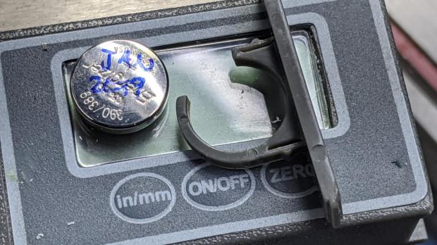
The last time I did this, I wedged a thin foam sheet below the display PCB to put a bit more pressure on the (+) contact tab sticking down from the middle of the plate:
Mini-Lathe DRO – battery compartment
The (-) contact is a pad on the PCB below the battery compartment. The glaring metal reflector is part of the curved cell retainer.
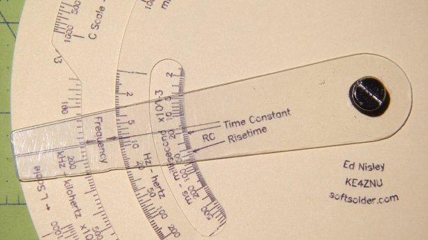
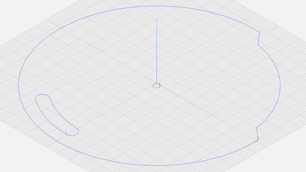
The middle deck is a disk with a notch exposing the FL scale, a cutout window exposing the inductive time constant / risetime scale, and a wee circle for the Chicago screw in the middle:
Given those, along with the deck radius and notch height (equals the underlying scale height), calculate four points defining the start and end of the ramps and connect the dots:
  local a0 = FLNotchOffset;
  local p0 = DeckRad * [cos(a0),sin(a0),-];

  local a1 = a0 + FLNotchArc;
  local p1 = DeckRad * [cos(a1),sin(a1),-];

  goto(p0);
  move([-,-,KnifeZ]);
  arc_cw(p1,-DeckRad);          // largest arc

  local r = DeckRad - ScaleHeight;
  local a3 = a1 - FLRampArc;
  local p3 = r * [cos(a3),sin(a3),-];

  local a4 = a0 + FLRampArc;
  local p4 = r * [cos(a4),sin(a4),-];

  move(p3);
  arc_cw(p4,r);                 // smallest arc

  move(p0);                     // end of notch

  arc_cw([DeckRad,0,-],DeckRad);      // round off corner
The arc_cw() functions draw arcs, as you’d expect, with a positive radius tracing the shortest arc and a negative radius for the longest arc. Although I know how that works, I must still preview the result to verify the G-Code does what I want, not what I said.
Cutting the window starts from its angular width and offset, which are hardcoded magic numbers from the Tek artifact, and proceeds similarly:
  local WindowArc = 39deg;

  local ac = -6 * ScaleArc;                  // center of window arc
  local r0 = DeckRad - ScaleHeight;         // outer
  local r1 = DeckRad - 2 * ScaleHeight;     // inner

  local aw = WindowArc - to_deg(atan(ScaleHeight,(r0 + r1)/2));    // window arc minus endcaps

  local p0 = r0 * [cos(ac + aw/2),sin(ac + aw/2),-];
  local p1 = r0 * [cos(ac - aw/2),sin(ac - aw/2),-];
  local p2 = r1 * [cos(ac - aw/2),sin(ac - aw/2),-];
  local p3 = r1 * [cos(ac + aw/2),sin(ac + aw/2),-];

  goto(p0);
  move([-,-,KnifeZ]);

  arc_cw(p1,r0);                          // smallest arc
  arc_cw(p2,ScaleHeight/2);               // half a circle
  arc_ccw(p3,r1);
  arc_cw(p0,ScaleHeight/2);
Trust me on this: incorrect radius signs generate unrecognizable outlines. Which, of course, is why you preview the G-Code before actually cutting anything:
Tek CC – MPCNC drag knife
A similar hunk of code cuts the top deck; the bottom deck is a simple circle.
The workflow, such as it is:
Tape a sheet of paper (Index stock, Basis 110 = 10 mil = 0.25 mm) at the center of the 3018-ProXL platform
Plot (“engrave”) the scales with a pen
Affix paper to a Cricut sticky mat taped to the MPCNC platform
Touch off the origin at the middle
Drag-cut (“mill”) the outlines
Less complex than it may appear, but the GCMC file now spits out two G-Code files per deck: one to engrave / draw the scales on the 3018 and another to mill / cut the outlines on the MPCNC.
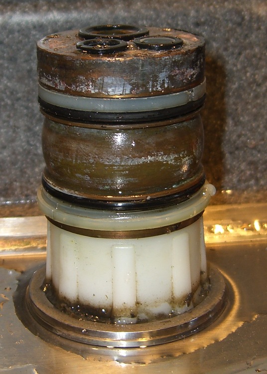
The O-ring replacement kit includes a pair of nylon (?) split rings which should provide bearing surfaces for the spout, but the upper ring sits in a groove putting its OD almost flush with the column:
Faucet column
This may be tolerance creep or just a design screwup, but the spout squashes the O-ring much more than (IMO) it should and wears it out entirely too soon.
This time around, I cut a strip of 0.4 mm thick polypropylene (from the Big Box o’ Clamshell Packages) long enough to wrap around the column and narrow enough to fit inside the groove, with the split ring holding it in place. The strip expands the ring’s OD to just barely fit inside the spout, so the spout now bears mostly on the ring, not the O-ring.
Despite measuring the groove OD and the spout ID, I had to cut-and-try several strips to find the proper thickness. Your mileage will certainly differ.
The spout now turns smoothly and freely, without leakage. We’ll see whether the new O-rings last longer than before.
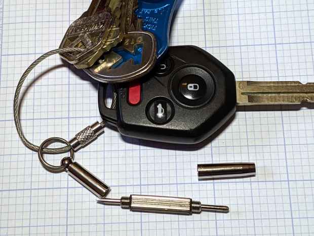
The far end has a 2.5 mm hex driver, although I’ve never encountered a nut for an M1×0.25 screw in the wild. It doesn’t fit an 0-80 nut and gulps 00-90 nuts, so it’s definitely hard metric.
My collection of glasses required an aggregate two turns of tightening, which prompted dBm to remind me of threadlock.
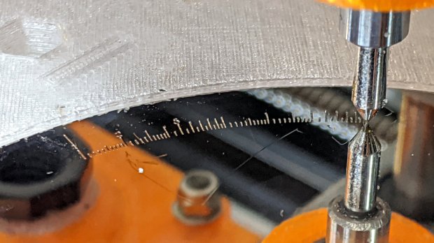
Engraving the Tektronix Circuit Computer bottom deck on a scrap hard drive platter suggested I’m entirely too much of a sissy about downforce on the diamond drag bit:
Tek CC – bottom deck – HD platter – L scale
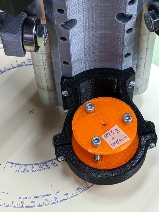
That’s at Z=-5 mm for 350 g of downforce, with the spring preloaded with 100 g at a 50 g/mm rate. More or less, anyhow.
The GCMC code automagically scales everything by the ratio of the actual platter OD to the original Tek bottom deck. Using 93 mm for a hard drive platter (actual OD = 95 mm) sets the scaling to 0.197 = 93/197, which makes the scale legends just barely visible:
Tek CC – bottom deck – scaled to HD platter
The thing looks lovely, though, with ticks engraved at 2400 mm/min and the text at 2000 mm/min. The problem turns out to be the time taken to run the Z axis down and up while engraving so many ticks and characters!
I cranked on another 2 mm = 100 g of preload:
CNC 3018-Pro – diamond bit downforce plot
The top graph shows the downforce in 0.1 mm increments, rising from 0.0 to 217 g in 0.3 mm, which illustrates what the Y intercept of the plot means in real life.
Engraving at Z=-3 mm will now produce 350 g of downforce and cut the Z axis travel time down by a bit less than half. I have no idea what the right force might be; more experiments are in order.
Two passes make the scratch deep enough to hold engraving crayon / lacquer / ink, without making it much wider. Laser engraving would surely work better.
In lieu of actually milling the cursor, this code scratches the perimeter:
  local dr = DeckBottomOD/2;
  local hr = CursorHubOD/2;
  local a = atan(hr - CursorTipWidth/2,dr);   // rough & ready approximation

  local p0 = hr * [sin(a),cos(a),-];          // upper tangent point on hub

  local c1 = [dr - CursorTipRadius,CursorTipWidth/2 - CursorTipRadius*cos(a),-];
  local p1 = c1 + [CursorTipRadius*sin(a),CursorTipRadius*cos(a),-];

  local p2 = c1 + [CursorTipRadius,0,-];      // around tip radius

  feedrate(KnifeSpeed);

  goto([-,-,TravelZ]);
  goto([-hr,0,-]);
  move([-,-,EngraveZ]);

  repeat(3) {
    arc_cw(p0,hr);
    move(p1);
    arc_cw(p2,CursorTipRadius);

    move([p2.x,-p2.y,-]);
    arc_cw([p1.x,-p1.y,-],CursorTipRadius);
    move([p0.x,-p0.y,-]);
    arc_cw([-hr,0,-],hr);
  }
Three passes makes it deep enough to snap along the line:
Tektronix Circuit Computer – cursor outline
If you look closely, though, you’ll find a little divot over on the left along the bottom edge, so I really must machine the thing.
Were I to go into production, I’d have to figure out a fixture, but I think I can just clamp a rough-cut acrylic rectangle to the Sherline’s table, mill half the perimeter, re-clamp without moving anything, then mill the other half.
Subtractive machining is such a bother!
The pivot holding the cursor and decks together is a “Chicago screw“, a.k.a. a “sex bolt“. I am not making this up.
During an evening KP session, the kitchen faucet handle jammed at the clockwise (hottest) end of its travel and refused to turn; it continued to move vertically and I turned off the water. This had happened before, so I knew roughly what to expect:
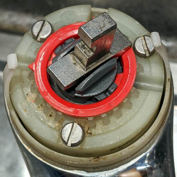
The pointer on the red hot limit safety stop ring should be aimed just right of the front screw, at the 0 position producing maximum hotness. The scale reads backwards, perhaps in units of increasing safety.
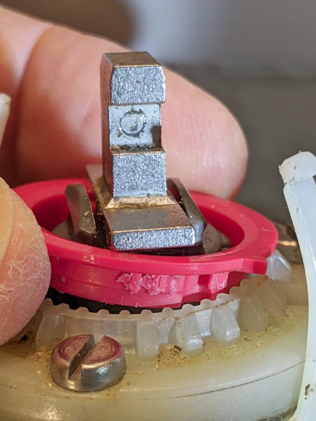
In that position, the ring prevents the valve core from turning counterclockwise, which explains the symptoms. With the water turned off (at the ball valves in the basement) and the valve stub tilted vertically, the ring popped loose (it shouldn’t move on its own) and exposed the problem:
Am Std Elite Faucet – wrecked hot limit splines – as found
Neither Mary nor I recall applying that much force to the handle, but ya never know.
The flanges protruding from the stem prevent you from removing the ring, but a pair of small diagonal cutters will chop right through the plastic. If you’re one of the six people depending on the limit stop to keep the water temperature under control, you probably don’t want to cut the ring out; I have no suggestions on how to repair it.
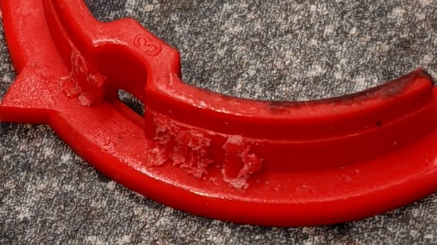
It’s obvious the splines won’t ever be the same again:
Am Std Elite Faucet – wrecked hot limit splines – detail 1
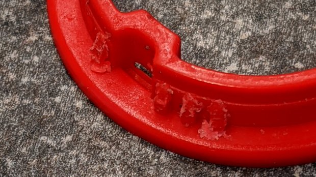
The ring has two sets of splines and they’re both wrecked:
Am Std Elite Faucet – wrecked hot limit splines – detail 2
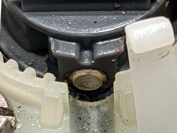
With the ring out of the way, it’s easy to see the trunnion shaft has moved leftward:
Am Std Elite Faucet – misaligned pivot shaft
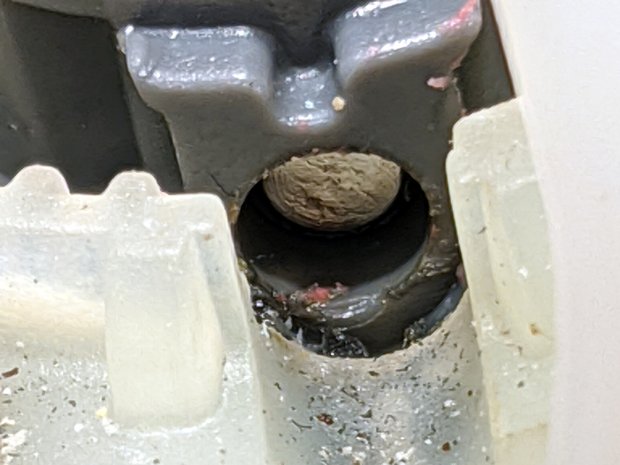
There’s essentially no clearance between the shaft and the ring, so it was rubbing against the ring, as evidenced by the red debris left behind when I tapped it to the far end of its travel:
Reassemble in reverse order and it works fine again.
I expect the shaft will resume moving leftward and eventually jam in the notch, probably after abrading the white plastic, but I don’t see how to lock it in place.