Ed Nisley's Blog: Shop notes, electronics, firmware, machinery, 3D printing, laser cuttery, and curiosities. Contents: 100% human thinking, 0% AI slop.
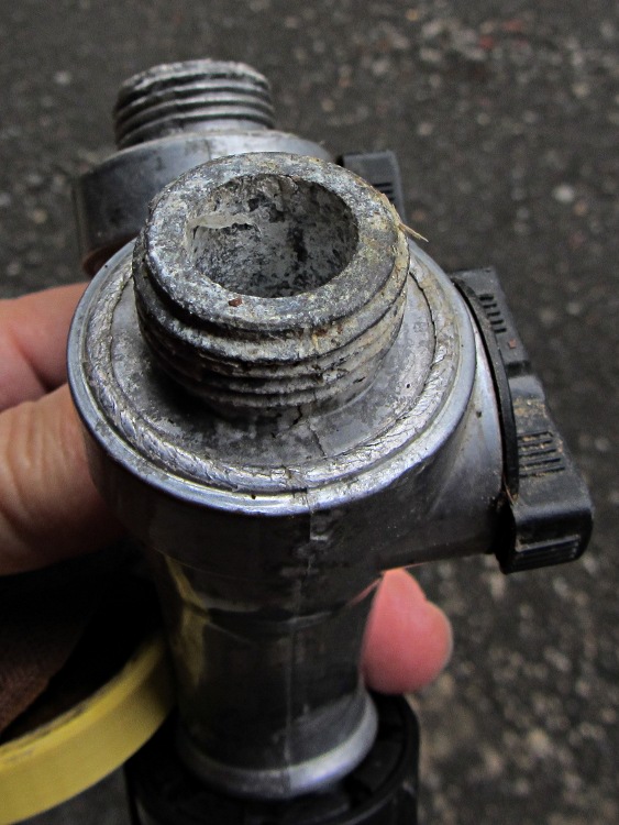
The corroded Y valve, minus another failed hose fitting, recently emerged from a heap o’ stuff on the Basement Laboratory Bench. This old photo gives you an idea of what happens to cheap pot metal in a garden:
Corroded Garden Y Valve
I dropped it Y-end-down into a container of white vinegar for a week, after which a few minutes of scrubbing produced a workable result:
Garden hose Y valve – after vinegar soak
The threads on the left side are pretty much gone. The hose fitting protected the threads on the right, but was corroded firmly in place; a penetrating oil soak and concerted muttering removed it.
All of the garden hoses and fittings out in Mary’s Vassar Farms plot have survived well beyond their best-used-by date. Given that we salvaged many hoses from the Farm’s end-of-season midden heaps, they don’t owe us much …
For the second time in a few months, the kitchen faucet handle stopped moving all the way to the left and the spout stopped dispensing hot water. The last time I did nothing and, after a few days, it resumed normal operation. Having had a while to think it over, this time I removed the handle and saw exactly what I expected:
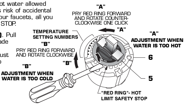
American Standard Elite 4453 4454 faucet – hot limit stop diagram
The red ring (the “hot limit safety stop”) fits into one of eight click-stop positions; the photo shows it in position 5, with 0 being just to the right of the bottom screw and 7 just below the horizontal notch across the middle.
The dark gray plastic feature inside the ring connects the metal handle (the out-of-focus silver stud aimed at you) to the valve assembly. The two lugs sticking out to its left and right bump into the inward-pointing red lugs as you rotate the handle leftward = clockwise = more hot. With the ring set to the 0 position, the red lugs overlap similar lugs molded into the light gray valve body that limit the rotation in both directions.
Observations:
You must pry the red ring upward to disengage the splines locking it into position
The gray lugs impose a hard stop in the counterclockwise direction = cold
There’s no upward force on the ring for any reason that I can imagine
We don’t pound on the faucet handle, so there’s no shock loading
I have no idea how the red ring could disengage its splines and move counterclockwise by five clicks all by itself.
I reset it to 0, reassembled the faucet with a dot of penetrating oil in the set screw, and it’s all good.
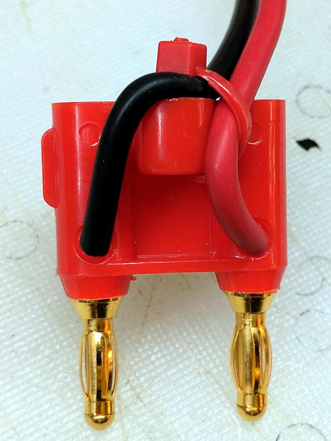
The second banana plug on one of my multimeters failed, so I finally got around to replacing them with a dual plug from the Drawer o’ Banana Stuff:
Dual banana plug – assembled
The bulky test leads don’t quite fit through the convenient retaining ring, so the zip tie holds ’em in place.
A setscrew at the base of each banana jack tunnel crunches the test lead wire against the plug base, but, alone among the collection, this plug had one missing screw. Rather than toss it away (or, worse, back in the Drawer), I decided to Solve The Problem once and for ever:
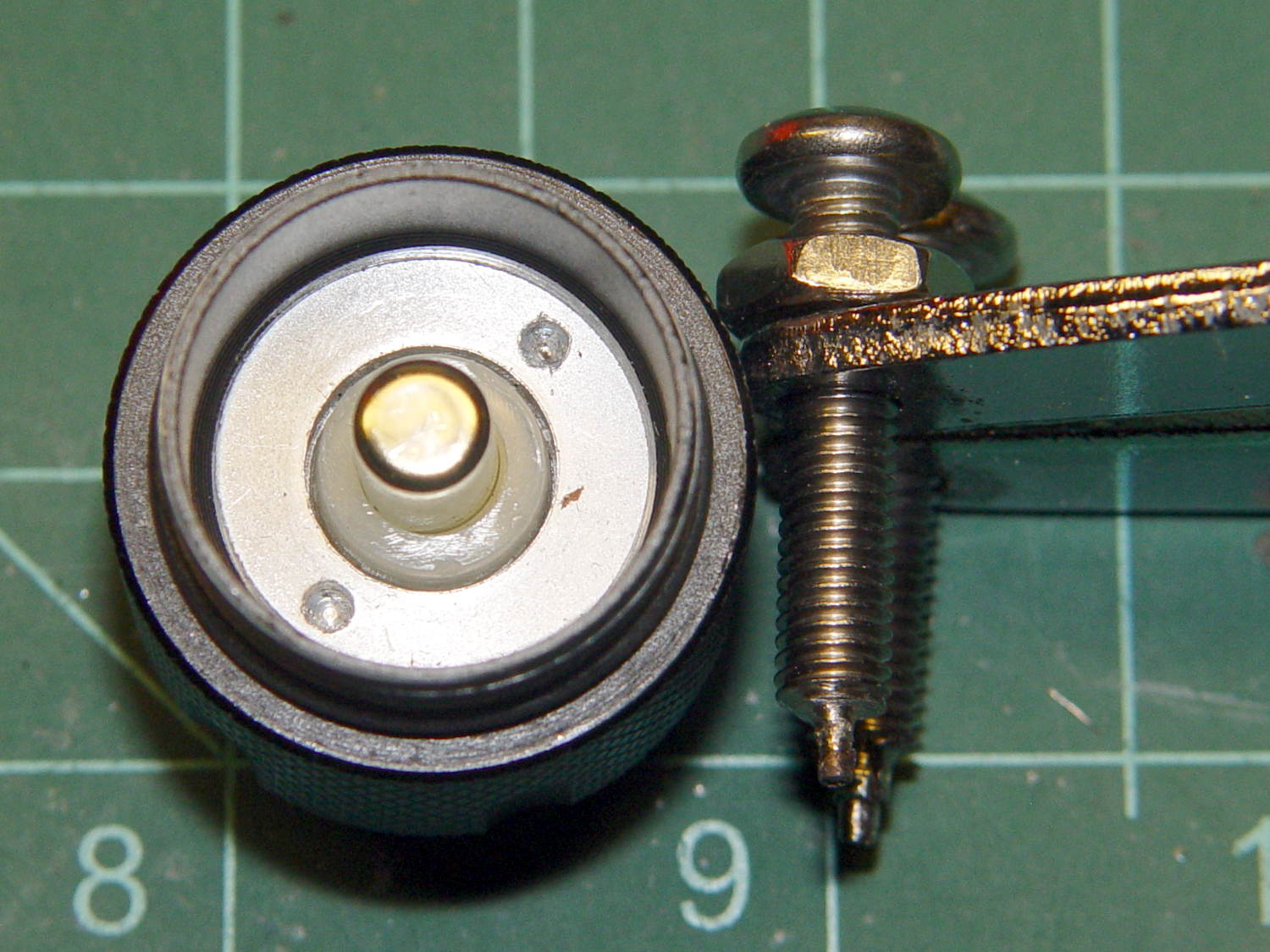
Dual banana plug – improvised clamp screw
That’s an ordinary M3 screw from the Drawer o’ Random M3 Stuff with its head hacksawed off, a slot crudely hacksawed slightly off-center into the end, then lightly filed to hide the worst damage. With a bit of luck, nobody will ever notice it …
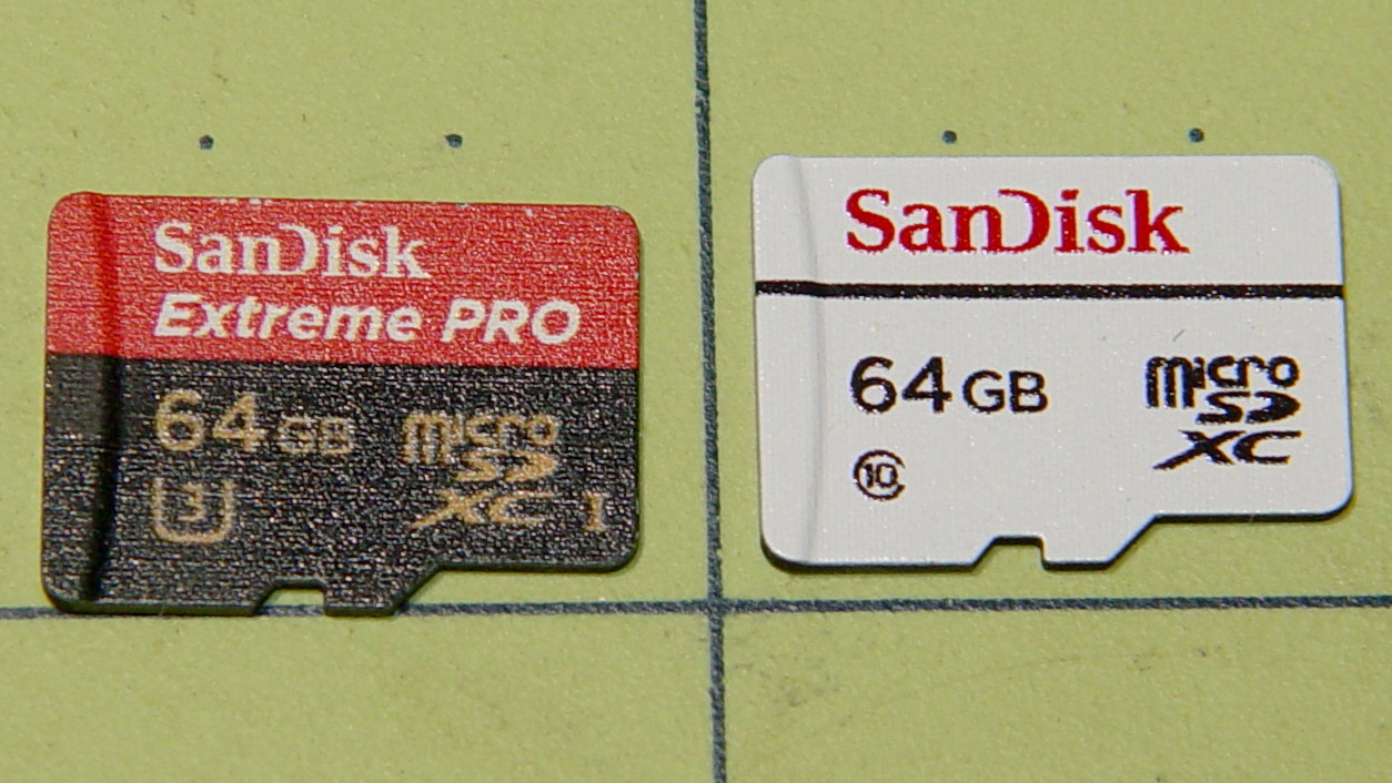
The Sandisk Extreme Pro 64 GB MicroSD card in the Sony HDR-AS30V died on the road once more, got reformatted, worked OK for a while, then kicked out catastrophic I/O errors after being mounted, so I swapped in the High Endurance card:
Sandisk – 64 GB MicroSDXC cards
The Extreme Pro still passes the f3probe tests, so it’s not completely dead, but if I can’t trust it in the helmet camera, it’s dead to me.
It survived 17 months of more-or-less continuous use, although we didn’t do nearly enough riding for three months early this year. Call it 14 months x five rides / week x 1 hour / ride = 300 hours of recording. Multiply by 4 GB / 22.75 minutes to get 3 TB of video, about 50 times its total capacity.
The never-sufficiently-to-be-damned Sony cards failed after less than 1 TB and 15-ish times capacity, making the Sandisk Extreme Pro much better. However, it’s painfully obvious these cards work better for low-intensity still-image recording, rather than continuous HD video.
Using them as Raspberry Pi“hard drives” surely falls somewhere between still cameras and video, although Octoprint’s video snapshots and streaming media must make ’em sweat.
We’ll see how Sandisk’s High Endurance memory works in precisely the application it’s labeled for.
From the start, the (second) J5 V2 flashlight had an erratic switch that flickered the LED at the slightest pressure. Not enough to switch modes, as it does with a half press, but enough to show something’s not quite right inside.
Taking it apart requires a pin wrench, which I have, but the deeply recessed ring required more reach than any of the tips I’ve made over the years. Introducing a pair of stainless steel 10-32 screws to Mr Grinder added two more pins to the collection:
J5V2 Flashlight – custom pin wrench
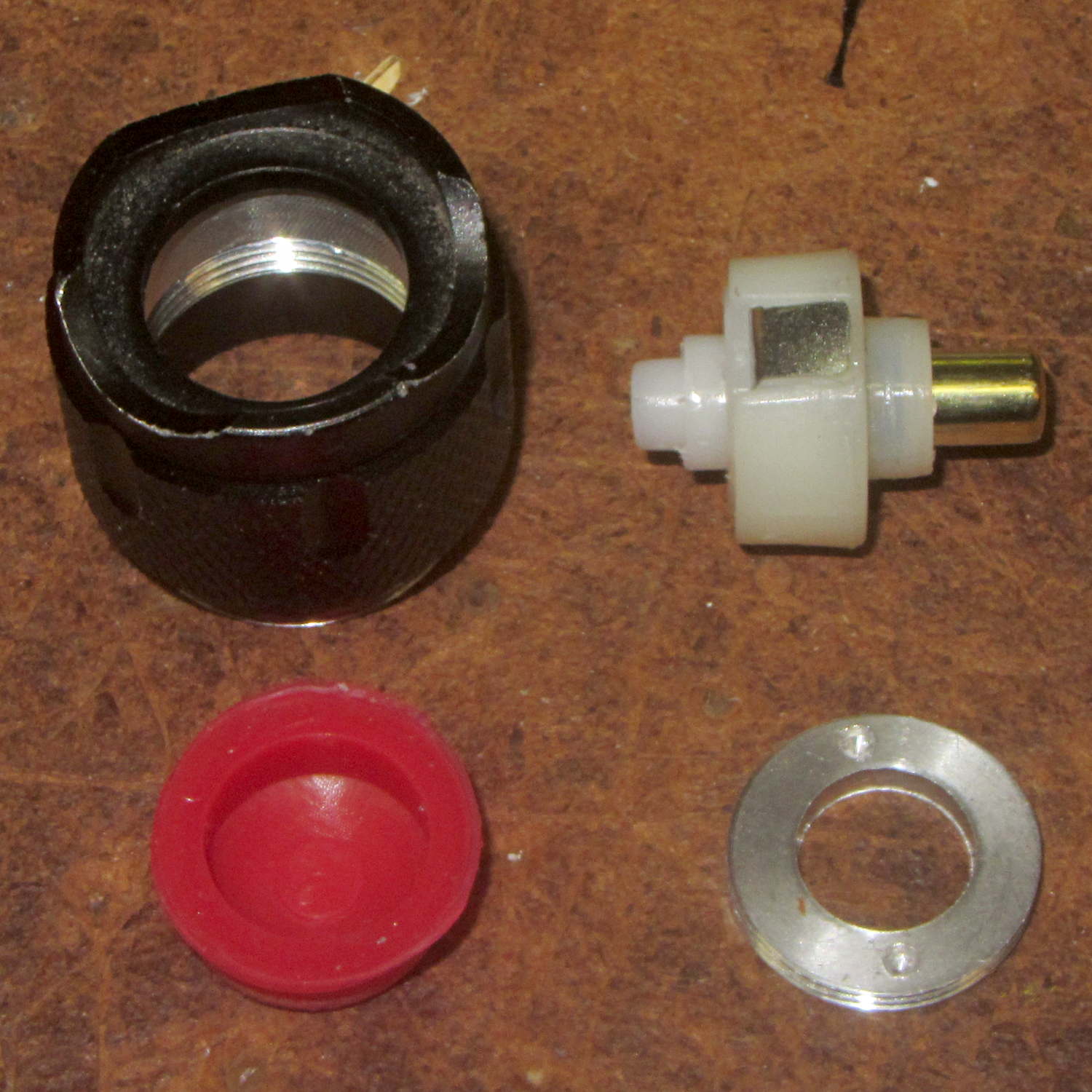
The lock ring in the flashlight cap turned out to be finger-loose, certainly contributing to the problem. Removing the lock ring, peeling the rubber dome out of the cap, and poking with a punch sufficed to drive out the guts of the switch assembly:
J5V2 Flashlight – switch parts
Which consists of, as you’d expect, the cheapest possible parts that don’t immediately fail.
The (steel) tab sticking out of the actual switch (in the upper right) contacts the inside of the (aluminum) cap. I bent it slightly outward, added a trace of DeoxIT Red, reassembled everything in reverse order, and it’s all good for the first time in its brief life.
The J5 V2 light claims 750 lumen output, but the spot is nowhere near twice as bright as the LC40 lights on the bikes and much dimmer than the LC90 light (which is too big for the bikes), all tweaked for equivalent-size illuminated areas. Given that lumens measure total output and candela measure lumen/steradian, there’s some wiggle room for misinterpretation.
My pocket camera has begun kvetching about a low battery rather more often than before, which suggests the batteries I’ve been using since 2014 have gone beyond their best-used-by date.
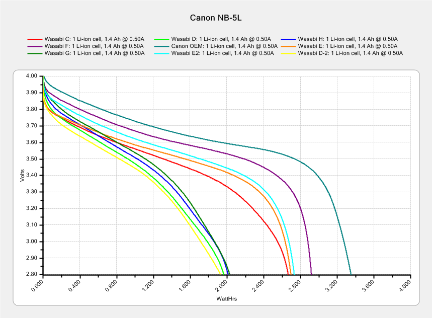
This came as no surprise:
Canon NB-5L – 2017-08-05
I re-ran a couple of the batteries to make sure they hadn’t faded away from disuse, which didn’t materially change the results. The lightly used Canon OEM battery continues to lead the, ah, pack.
The camera’s lens capsule accumulated a fair bit of dust from many years in my pocket, which lowers its overall contrast and wrecks the high f/ images produced with the microscope adapter.
The tiny lip holding the new LED ring light into the microscope snout lacked enough traction and deposited the ring light on the desk. Having picked up a roll of Scotch Extreme Mounting Tape to see how well it works to attach LEDs to vacuum tubes, I’ll see how well it affixes a ring light to a microscope:
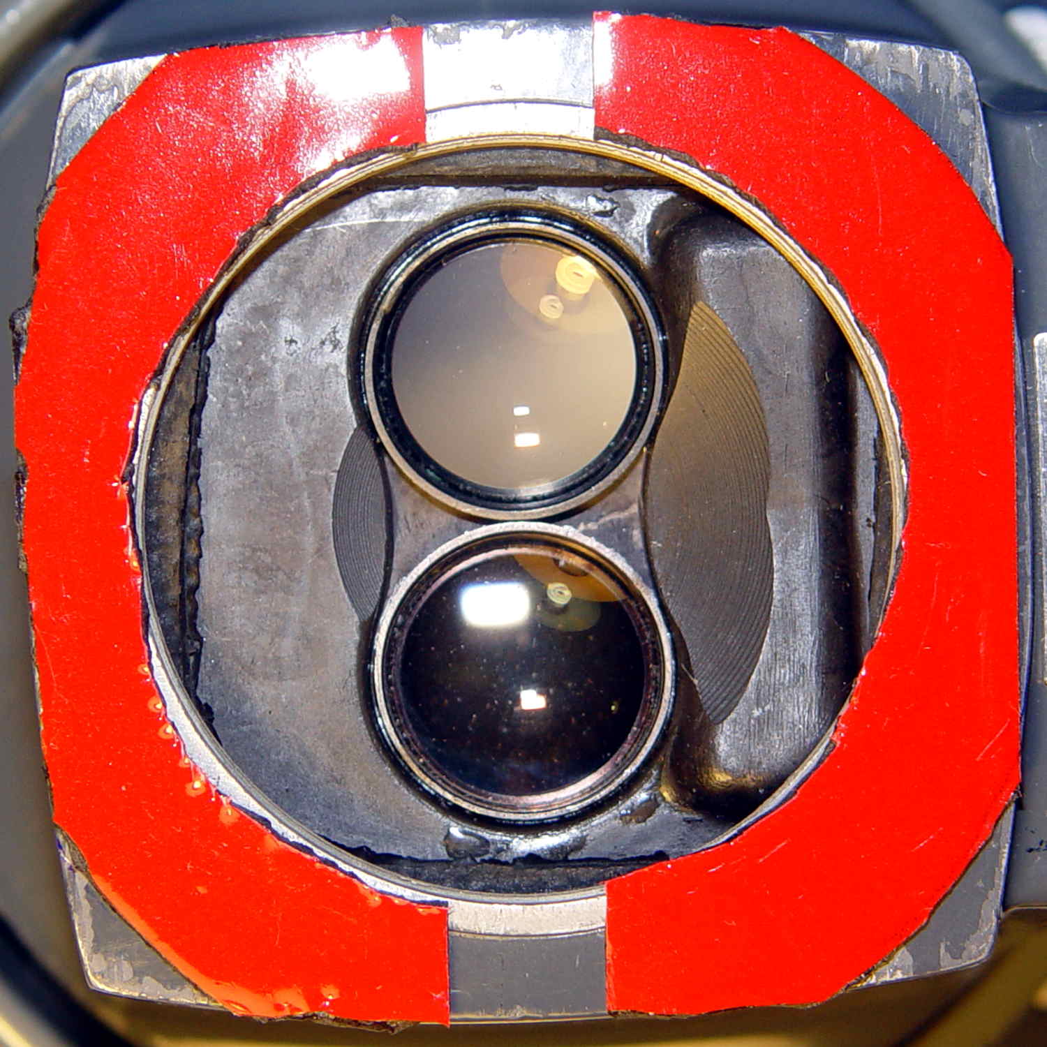
Stereo zoom microscope – taped snout
The red plastic film separates the tape layers on the spool; the tape itself consists of incredibly sticky, gooey adhesive on a very flexible foam backing. As you can tell from the ragged edges, cutting it requires some effort, with the adhesive instantly gumming up scissors. I applied a razor knife around the microscope snout’s perimeter, pressing from the red film side and pulling the cut sections apart as I went.
The adhesive exposed on the edges of the roll will glue it to anything it touches, so hang up the roll. Laying it on a shelf will definitely cause heartache & confusion.
The instructions on the back label suggest 2 square inches of tape will hold 1 pound:
Scotch Extreme Mounting Tape – label
Given that the ring light weighs a few ounces, tops, those two strips should do fine.