Ed Nisley's Blog: Shop notes, electronics, firmware, machinery, 3D printing, laser cuttery, and curiosities. Contents: 100% human thinking, 0% AI slop.
Over the course of those six years I’ve ridden about 6 × 2500 = 15000 miles, maybe more, maybe less. I can ride at 15 mph for a while, but 12 mph seems a more reasonable overall estimate, making for a bit over 1000 hours. Figure the bike spends that much time sitting outdoors at the far end of the ride and you’re looking at what 2000+ hours of sunlight does to ABS.
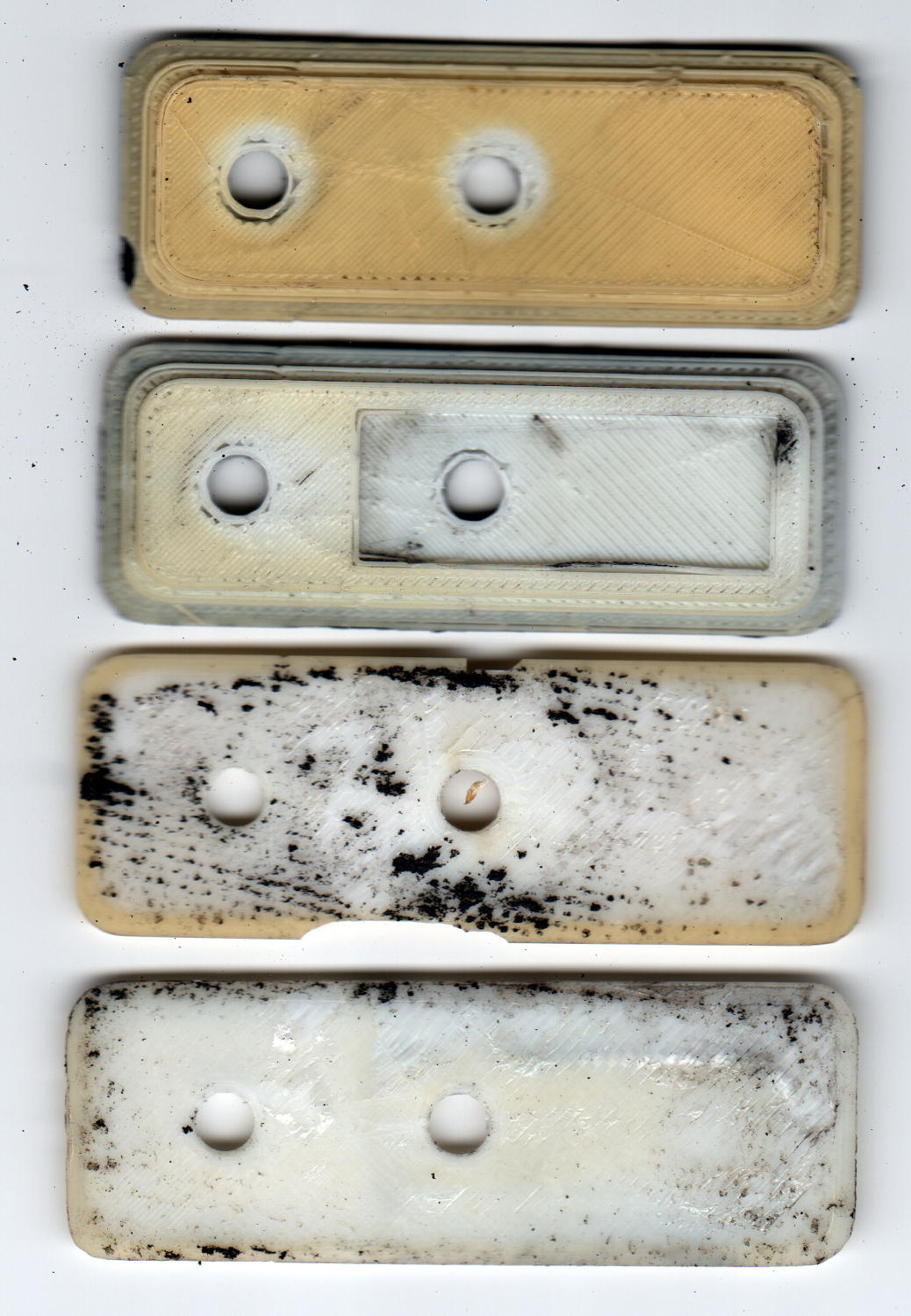
In addition to discoloration, the plates have become brittle, as shown in the chips in third one down, and permanently deformed due to the pressure of the nylon bolts compressing the black foam against the fairing.
A closer look at the top plate:
ABS Fairing Plates – 6 years – detail
My 3D print quality has improved a lot since then.
New plates of a different design are, as NASA puts it, “in work”.
The pix come from the new LiDE 120 scanner. It does a good job with the color, but has (for good reason) an essentially zero depth of field: if it’s not on the glass, it’s out of focus.
Came up from the Basement Laboratory to find my Dell Optiplex 980 PC had failed, with the power button and diagnostic 1 + 3 LEDs blinking amber. They built it back in June 2010, so section 3 of the Dell reference applies, the power supply status LED on the back panel was off, and, going straight to the heart of matter, I popped the top, disconnected the internal power supply cables, and poked the power supply test button:
Optiplex 980 Power Supply – rear panel test button
… and it’s dead.
Inside, the system board sports a Mini-ATX power supply connector:
Optiplex 980 – Mini-ATX power connector
I originally hoped to swap a supply from an Optiplex 755 (also in a Small Form Factor case) residing on the recycle heap, but it has an ordinary ATX connector:
Optiplex 755 – ATX power connector
So I moved the 980’s SSD and dual-Displayport video card into the 755, fired that devil up, and … it worked!
With my desktop back in action, albeit somewhat slower, I popped the dead supply’s case by violating the Warranty Void If This Label Removed sticker to unscrew the last screw:
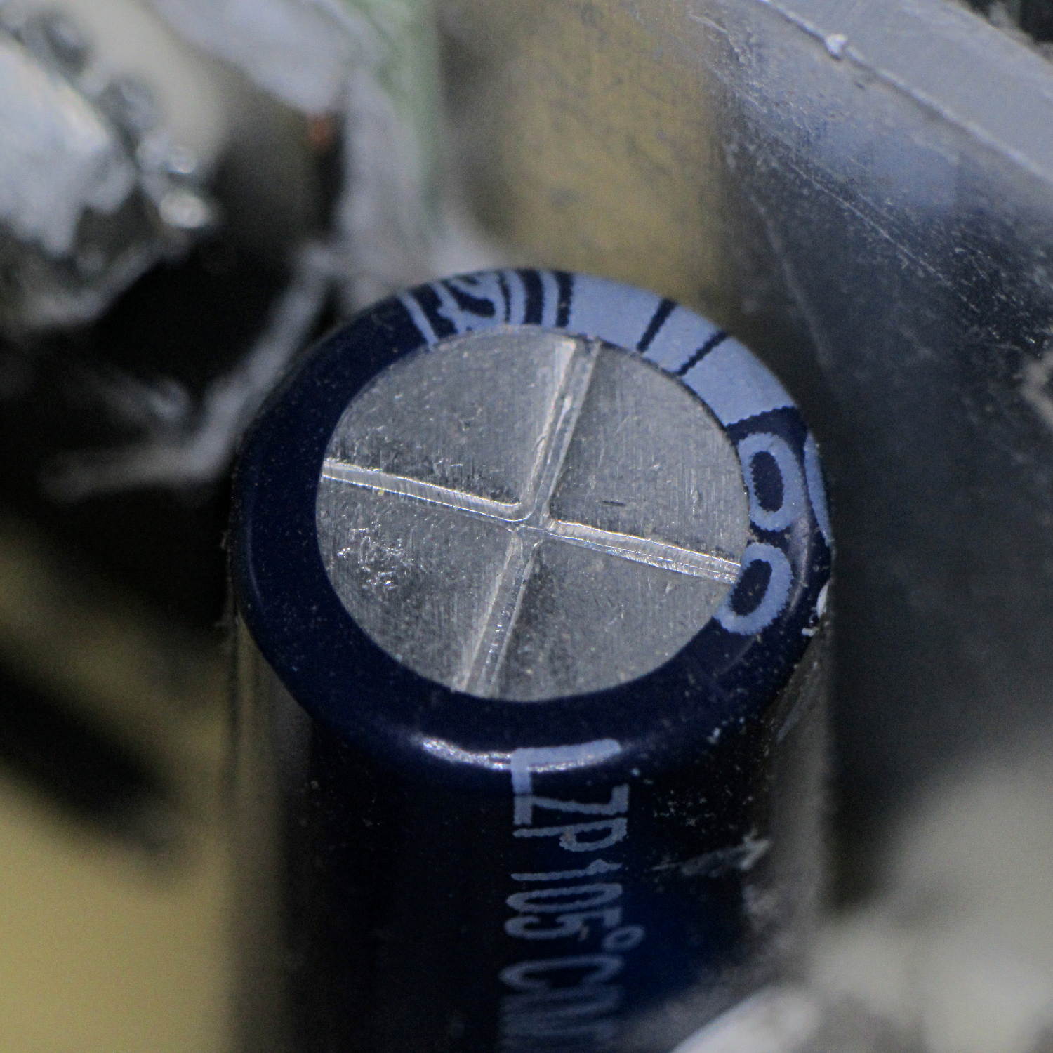
The cluster of caps on the upper right have bulged pressure-relief lids, like this:
Optiplex 980 – Bulging capacitor 1
And this:
Optiplex 980 – Bulging capacitor 2
And this:
Optiplex 980 – Bulging capacitor 3
None had ruptured, but they’re obviously feeling a bit nauseous.
Given the 980’s mid-2010 manufacturing date, this probably isn’t capacitor plague, just simple overheating from operating in a dead-air zone amid all those heatsinks and wires. Some of the Usual Unnamed Sources suggest overheating the capacitors is how manufacturers ensure their hardware doesn’t last forever, without being obvious about planned obsolescence; I’m loathe to ascribe to malice what can be explained by design desperation.
A Genuine Dell replacement supply from eBay ($25 delivered) came from yet another “small form factor” Dell chassis, so it isn’t quite the same size, lacks a supply test button / LED status light, and doesn’t quite fit:
Optiplex 980 – replacement supply misfit
Nothing a sheet metal nibbling tool can’t fix, though, given I haven’t developed a deep emotional attachment to the chassis. I gnawed off the left side of the frame and squared up the rim around the lower screw, after which the opening fit the supply pretty well, although the latching tab bent up from the bottom of the chassis didn’t quite engage the far end of the supply. No big deal: it’s not in a high-vibration environment.
The new-to-me supply also carries an ATX connector, but the eBay seller included a Mini-ATX adapter. Jamming the adapter + wires into the space available required concerted muttering, assisted by tucking the SSD under the DVD-RW drive. No pictures, as it’s a classic seven pounds in a five pound box situation.
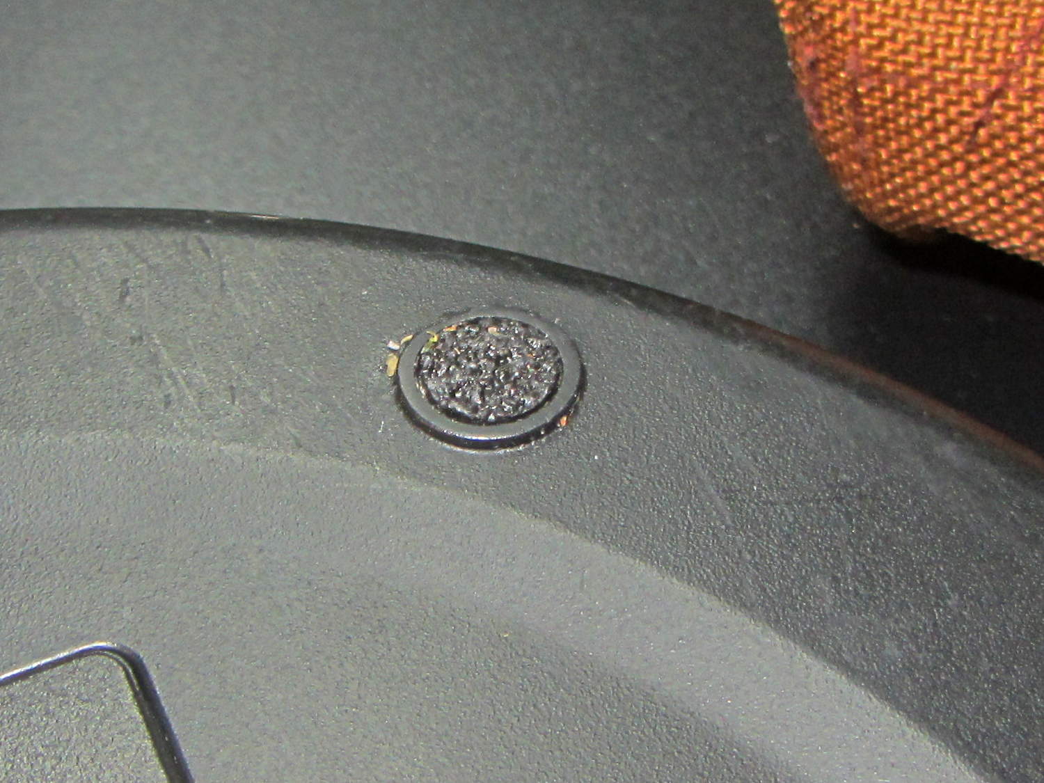
Our long-suffering kitchen scale lost a pair of feet, most likely becausethose two feet do most of the skidding as we slide it onto a shelf below a cabinet. The scale has (well, had) six silicone rubber feet:
Amazon EK3211 Scale – OEM foot
The vagaries of color photography turned a neutral-gray silicone disk into that weird blue.
A pair of ¼ inch disks punched from non-skid textured rubber tape fit perfectly into the recesses:
Amazon EK3211 Scale – tread foot
Now, we’ll see how tread adhesive withstands the same abuse.
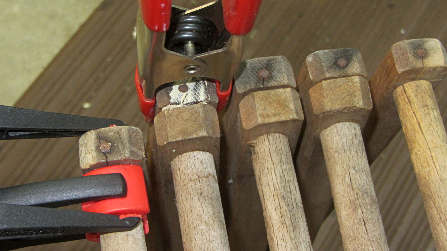
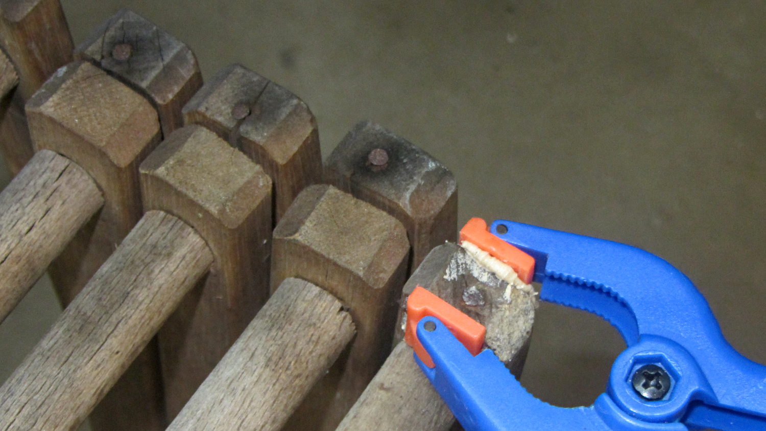
Despite having sworn a mighty oath to the contrary, I found myself doing this again:
Clothes Rack – end clamp
A strut on the other end of the dowel split across its face:
Clothes Rack – split clamp
The white stuff is wood-filled epoxy, normally used to repair rotted wood, left over from another project. I’ll claim this tests its mechanical strength against peeling forces.
Easily determined by inspection: a sensible person would toss the rack, but …
The two knockoff Neopixeltestfixtures went dark while their USB charger accompanied me on a trip, so they spent a few days at ambient basement conditions. When I plugged them back into the charger, pretty much the entire array lit up in pinball panic mode:
WS2812 LED – test fixture multiple failures
Turns out three more WS2812 chips failed in quick succession. I’ve hotwired around the deaders (output disconnected, next chip input in parallel) and, as with the other zombies, they sometimes work and sometimes flicker. That’s five failures in 28 LEDs over four months, a bit under 3000 operating hours.
For lack of a better explanation: the cool chips pulled relatively moist air through their failed silicone encapsulation, quietly rotted out in the dark, then failed when reheated. After they spend enough time flailing around, the more-or-less normal operating temperatures drives out the moisture and they (sometimes) resume working.
Remember, all of them passed the Josh Sharpie Test, so you can’t identify weak ones ahead of time.
I wired a resistive joystick to the knockoff Nano controlling the crystal tester and connected the button to an analog input because I have a lot of those left over and why not. Unfortunately, the ADC returned a sequence of random-ish numbers indicating the button didn’t have a pullup to +5 V.
One might be forgiven for assuming the pads marked R5 would hold such a pullup resistor, had the joystick not been relentlessly cost-reduced:
Keyes resistive joystick – R5 location
One would, of course, be completely wrong.
Having been around this blockseveral times, I measured the pad-to-pin resistances and found R5 firmly affixed to the GND and +5V pins, with the SW (a.k.a. button) pin floating free. Pressing the joystick hat closes the switch next to R5, thereby connecting the SW pin to GND.
Baffles me. Maybe a fresh intern did the PCB layout and just misplaced the resistor?
So I soldered an ordinary resistor (*) between the +5 V and SW pins:
Keyes resistive joystick – button pullup
Now it works just as it should.
(*) For long-lost reasons, I have a zillion 12.4 kΩ 1% resistors appearing in place of simple 10 kΩ resistors.
The plotter I received works beautifully, except that the carousel doesn’t rotate. I found a YouTube video showing a 7475a running with the cover off, and there’s a little plastic piece – it looks like a teardrop – that advances the carousel, and is apparently part of the carousel motor assembly. Mine is missing that piece …
The keyword is Geneva drive, a wonderfully simple technique to convert one rotation of the stepper motor into 1/6 turn of the pen carousel, with no need for fancy sensors.
Back in the day, you could get the entire Pen Carousel Housing Assembly w/ Motor (PN 07475-60175) as a unit and the Carousel Motor Only(PN 3140-0687) as a separate thing, but not the Geneva drive wheel:
HP7475A Carousel – Geneva drive cam
The cam’s drive wheel end (in inches, because early 1980s):
0.25 thick overall
0.10 thick plate under pin end
1.09 OD – rounded end
The pin sticking up from the cam:
0.154 OD (or fit to slot?)
0.16 tall (above base plate)
I have no good (i.e., easy + accurate) way to measure the distance from the motor shaft to the pin, but I doubt it’s critical. As long as the pin doesn’t quite whack the hub end of the slot, it’s all good:
HP7475A Carousel – cam driving
The 0.10 plate + 0.16 pin height don’t quite add up to the 0.25 overall measurement, but that’s certainly measurement error. I’d round the pin length downward and carve the drive from a 1/4 inch sheet.
A 3D printed part would probably work, apart from the accuracy required to fit the D-shaped motor shaft. Perhaps a round hole, reamed to fit the shaft, carefully aligned / positioned, with epoxy filling the D-shaped void, would suffice. A dent in the round hole would give the epoxy something to grab.
I’d be sorely tempted to use an actual metal / plastic rod for the pin, rather than depend on a stack of semi-fused plastic disks. The pin must withstand hitting the end of the “missing” slot during the power-on indexing rotation, because turning the carousel isn’t quite a non-contact sport. Normally, though, it enters the end of the slot without much fuss:
HP7475A Carousel – cam engaging
The blocked slot sits at the bottom of that picture, with a small locating pin sticking upward just above the circular feature at the end of the arm: we’re seeing the negative of a plug inserted into the original injection mold.